How does it work ?
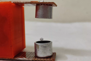
A basic acoustic levitator has two main parts: a transducer, which is a vibrating surface that emits sound, and a reflector. Often, the transducer and reflector have concave surfaces to help focus the sound. A sound wave moves away from the transducer and bounces off the reflector.
By placing a reflector away from a transducer by a multiple of half a wavelength, the acoustic levitator creates a standing wave.
stationary sound waves have defined nodes, or areas of minimum pressure, and antinodes, areas of maximum pressure. The nodes of a standing wave are at the center of the acoustic levitation. Although the sound is a longitudinal wave, most of the illustrations depict the sound as a transverse wave. This is simply because transverse waves are easier to visualize than longitudinal waves.

When the wave orientation is parallel to the gravitational attraction, parts of the standing wave have a constant downward pressure and others have a constant upward pressure as illustrated in the image below. The knots have very little pressure. Objects gather just below nodes, where the amount of pressure a sound wave can exert on a surface balances the force of gravity.
So we see that the mass of the particle really matters the size and the amount of gravitational force depends on it! The size of the levitated particle is also important, if the particle is too large it could interfere with another node or anti-node.
Necessary components
• Arduino Uno
• HC-SR04 ultrasound module
• L239d H-bridge module L298
• 7.4V battery or power supply
• Connecting cable.
Circuit wiring diagram

The specially programmed Arduino board acts as an astable multivibrator. To do this, the internal timer of the Atmega328 microcontroller has been appropriately programmed. In this way it was possible to generate a square wave signal, taken from the I / O pins of the boards, which are pins A0 and A1 respectively.
The frequency of the output signal is about 40 KHz, perfect for driving the capsules used.
Finally, the L293D power driver (alternative L298) is capable of delivering the current required by the capsules.
The Arduino clock runs at 16 MHz, this is the maximum speed at which timers can increase their counters.
REALIZATION
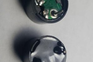
First we need to unsolder the transmitter and receiver from the ultrasound module. Also remove the protective cover, then connect the long cables to it. Then place the transmitter and receiver on top of each other, remember, the position of the ultrasonic transducers is very important. They should be facing each other in the opposite direction, which is very important, and they should be in the same line so that the ultrasonic sound waves can travel and intersect in opposite directions.
Please watch the making video for a better understanding
Programming
The coding is very simple, just a few lines. Using this little code with the help of a timer and interrupt functions, we are doing high or low (0/1) and generating an oscillating signal of 40Khz at the Arduino's A0 and A1 output pins.
 Ingeimaks

 david
david
