Canine Defense Technologi
-
Spot Optic Pod Component Integration & Testing
02/10/2023 at 05:50 • 0 commentsBench Test
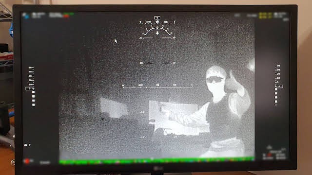
This week we've made a lot of progress in bench testing and integrating the components onto the Optics Pod. By far the most challenging part was having multiple cameras work together in harmony in the HD videolink, but thanks to the help of the Open H.D. community devs in the latest Evo release, we got the video stream working smoothly. It took a bit of hardware changes and firmware tweaks to perfect, but we successfully got a picture in picture working with a primary color day and night EO video stream, and a view from the IR thermal camera in the corner. Some quick field tests were done, but we are excited to continue on for more long term outdoor tests of all the components in the near future.
![]()
Monitor view of successful wireless transmission of the thermal camera!
![]()
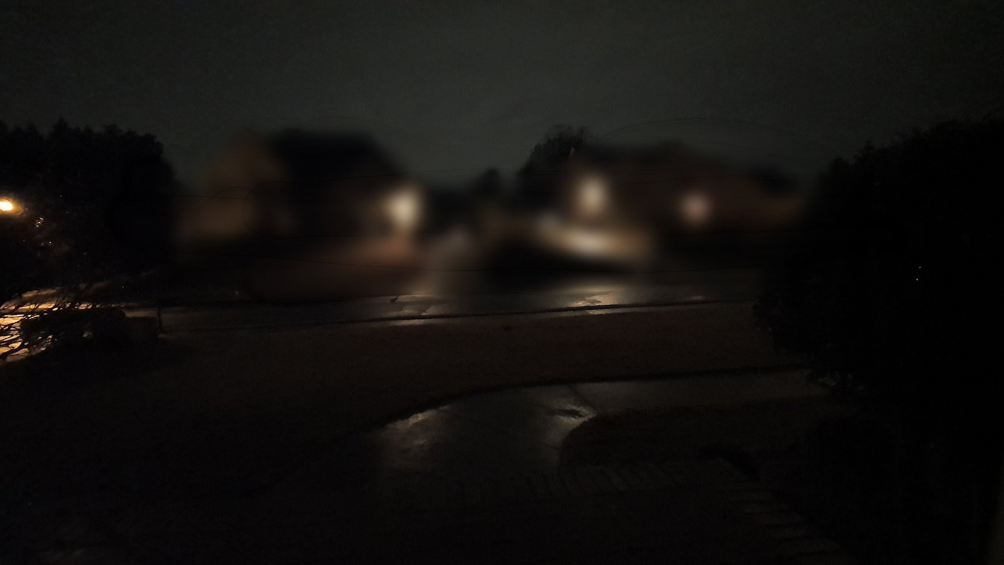
What the phone camera captures in low light mode.
![]()
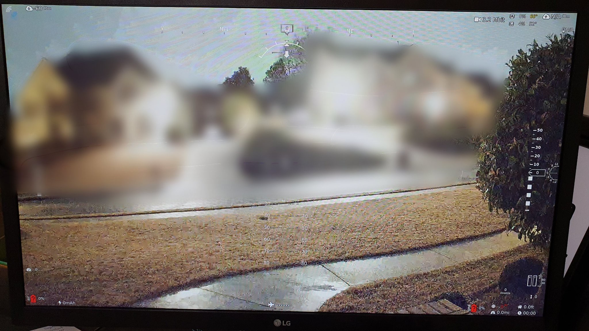
What the starlight low light EO captures off the wireless camera feed.
Optic Component Integration
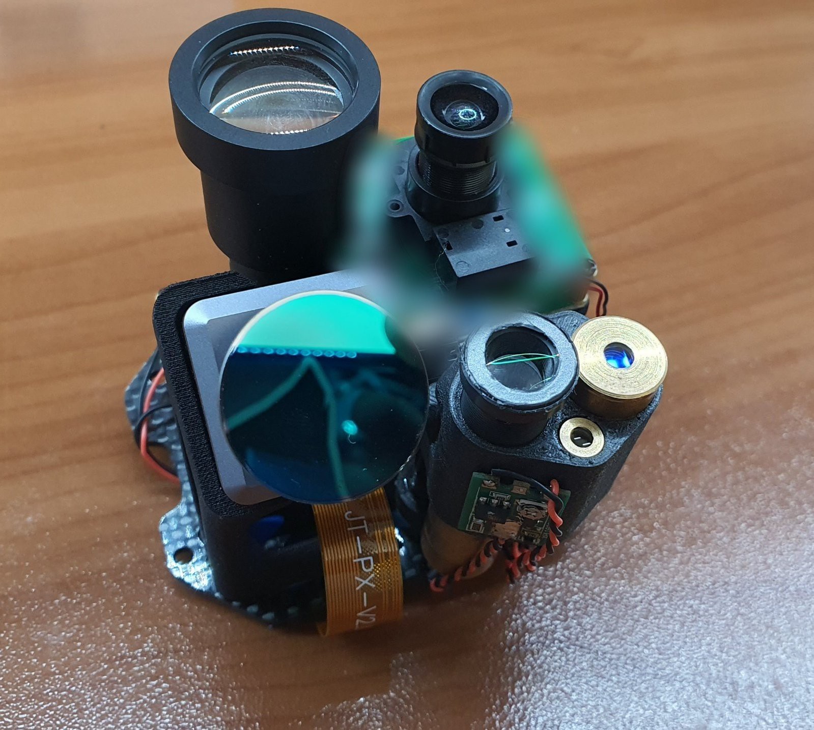
Now that we validated all the components nominal operation, we proceeded with integrating them onto the primary carbon fiber optic frame. The space was pretty tight with the amount of components that had to be packed into such a small space, but as validated virtually in CAD, all the components successfully integrated into the frame. As a quick check before proceeding with permanent fixation into the enclosure, the entire assembly was dry fitted to ensure correct tolerances. We are very excited to take this into the field and see its performance for both day and night!
View of optical components mounted onto primary optic frame.
Fitment check of the enclosure with the optic assembly stack inside.
-
Teaser Video and Stealth Blade Demo!
01/04/2023 at 04:42 • 5 commentsTeaser Video 2
Give it a watch, it's eye candy, we worked hard on the cinematography! If you've been reading these logs, you will recognize many of theses snippets we filmed during R&D!
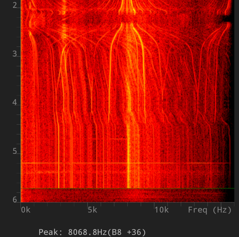
Stealth Blade DemoCheck out the acoustic test demo of our stealth blades! Decreasing volume at the RPM we're working with is very hard, but by raising the pitch and tightening the resonating frequency, it further helps mask the acoustic signature of the drone by eliminating the familiar chopping sound associated with drones! Keep an eye on the waveform!
-
Battery Charger & Testing Rig Development
12/31/2022 at 16:42 • 0 commentsRuggedized Battery Charger Build
Having a reliable charging solution for a UAS system like this is critical. However one of the many challenges is how fragile and complicated drone chargers can be. The idea here was to treat the charging system as an integral part of the entire drone, ground station, and ground support ecosystem by making a rugged portable all-in-one charging solution.
V1 Prototype
With V1 the plan was to make the entire charger from scratch, including the Li-Ion balancing circuit. This was a mistake! During testing, it overcharged the cells and damaged one of the test batteries. It also failed to demonstrate proper balancing. The root of the issue was the cheap battery management control board, it's low-quality components and cheap build quality yielded very unreliable results. At this point the charger was too dangerous to operate, so we decided to scrap it and move onto a different route.
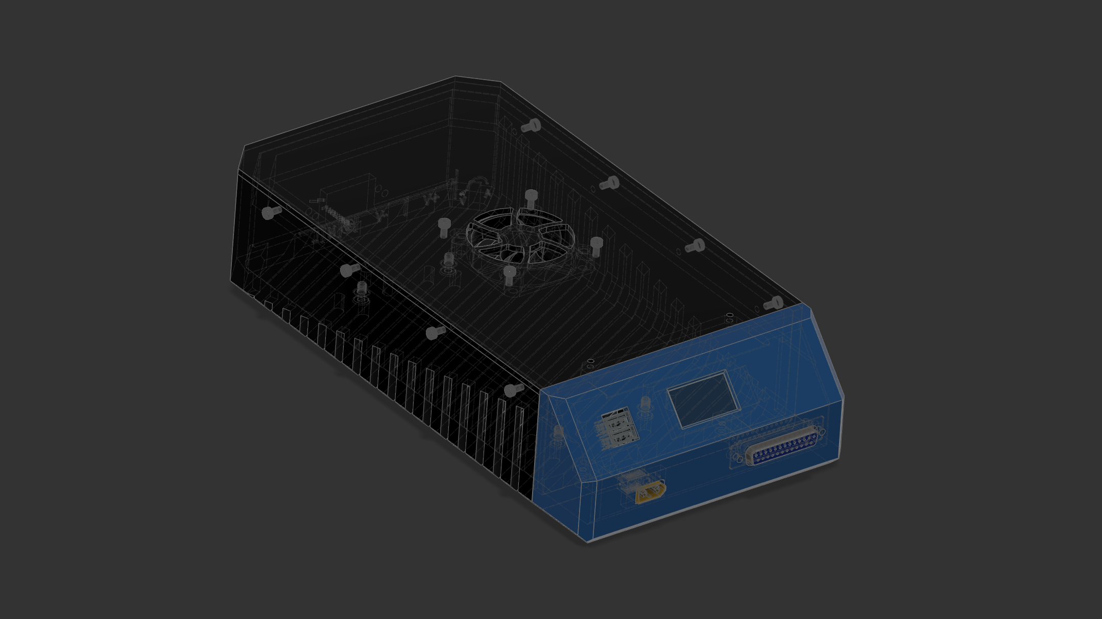
![]()
CAD view of V1 charger design
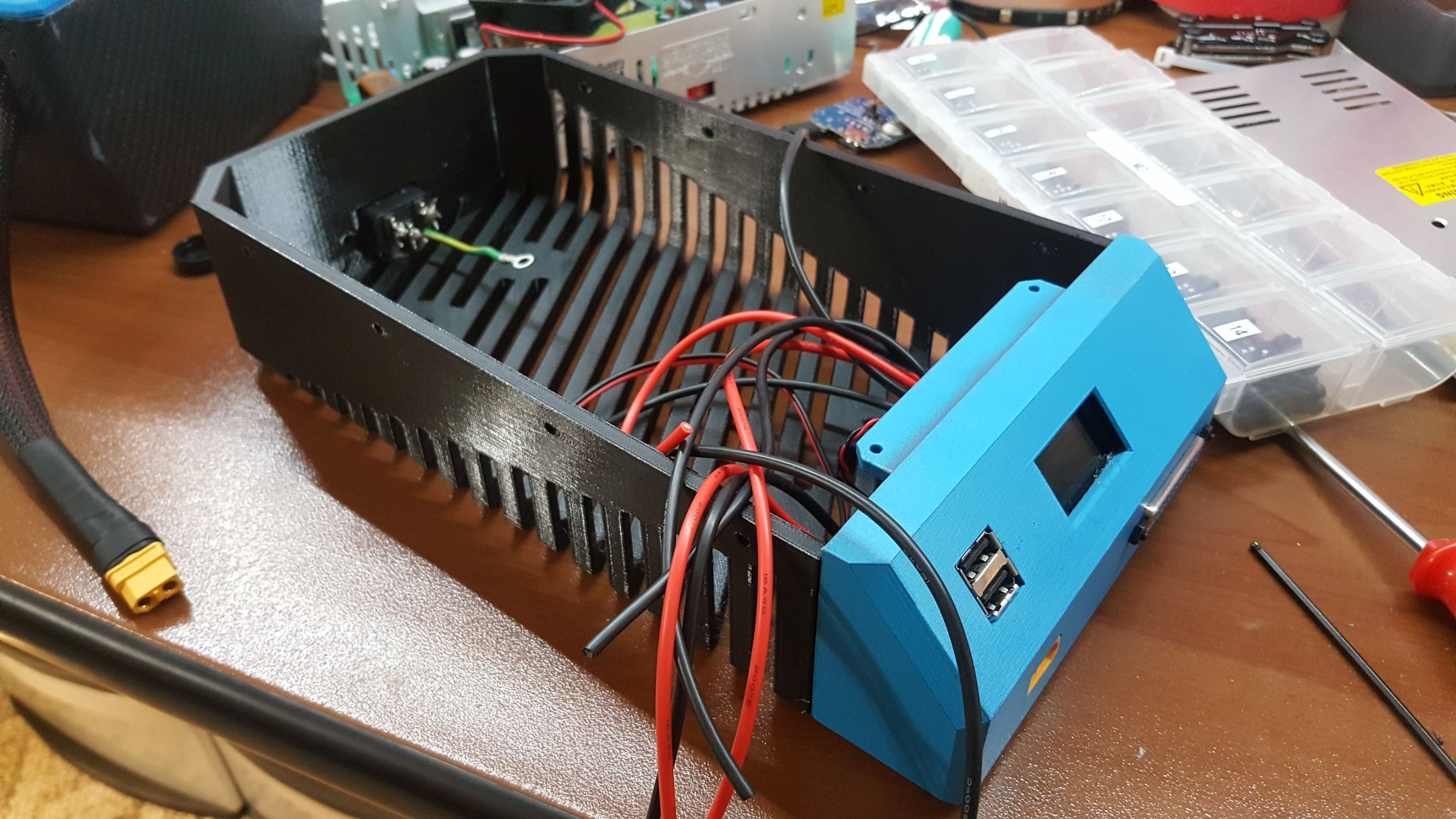
![]()
View of V1 during integration and assembly
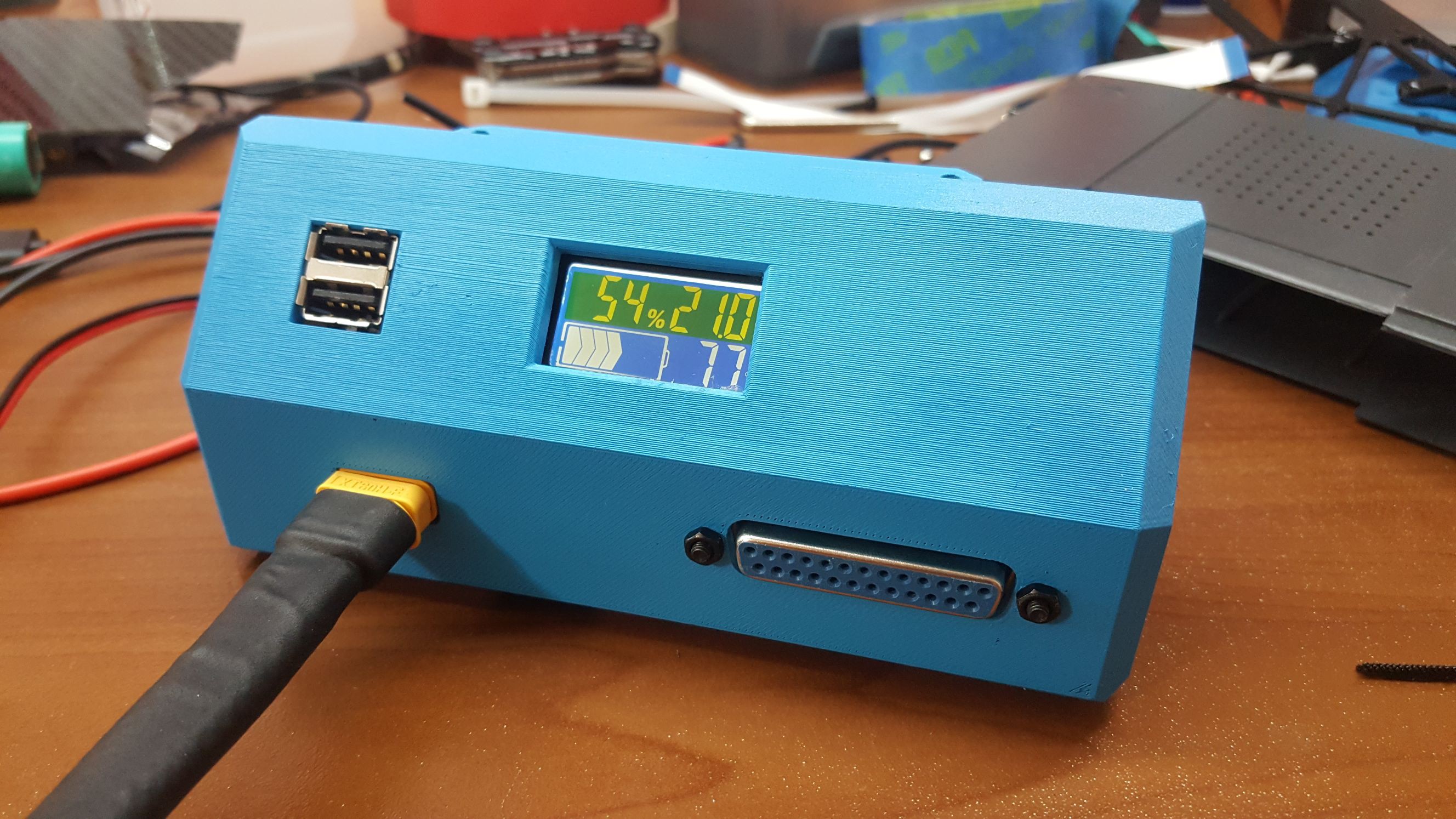
![]()
View of V1 during its first charge test before fully being enclosed
V2
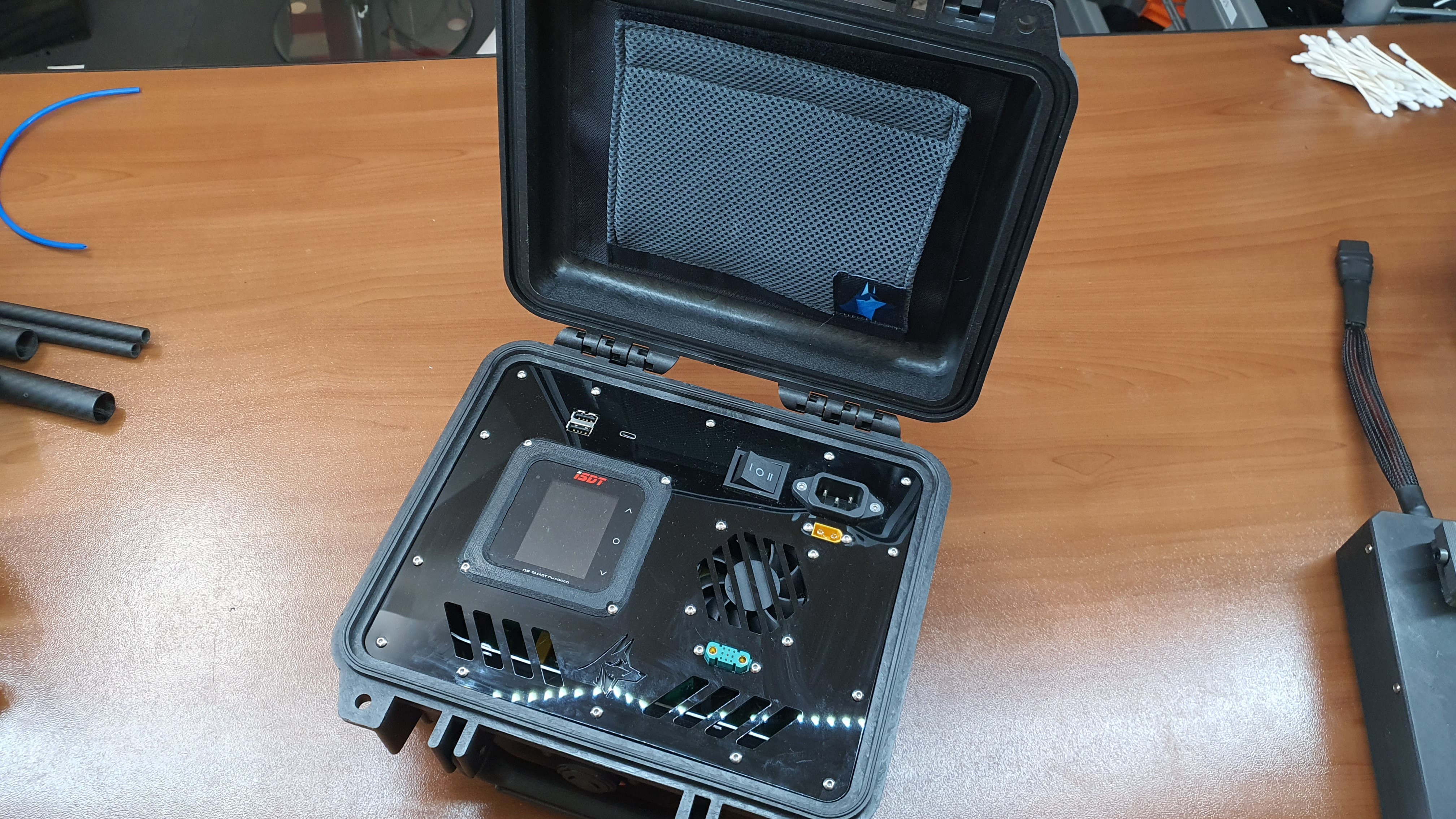
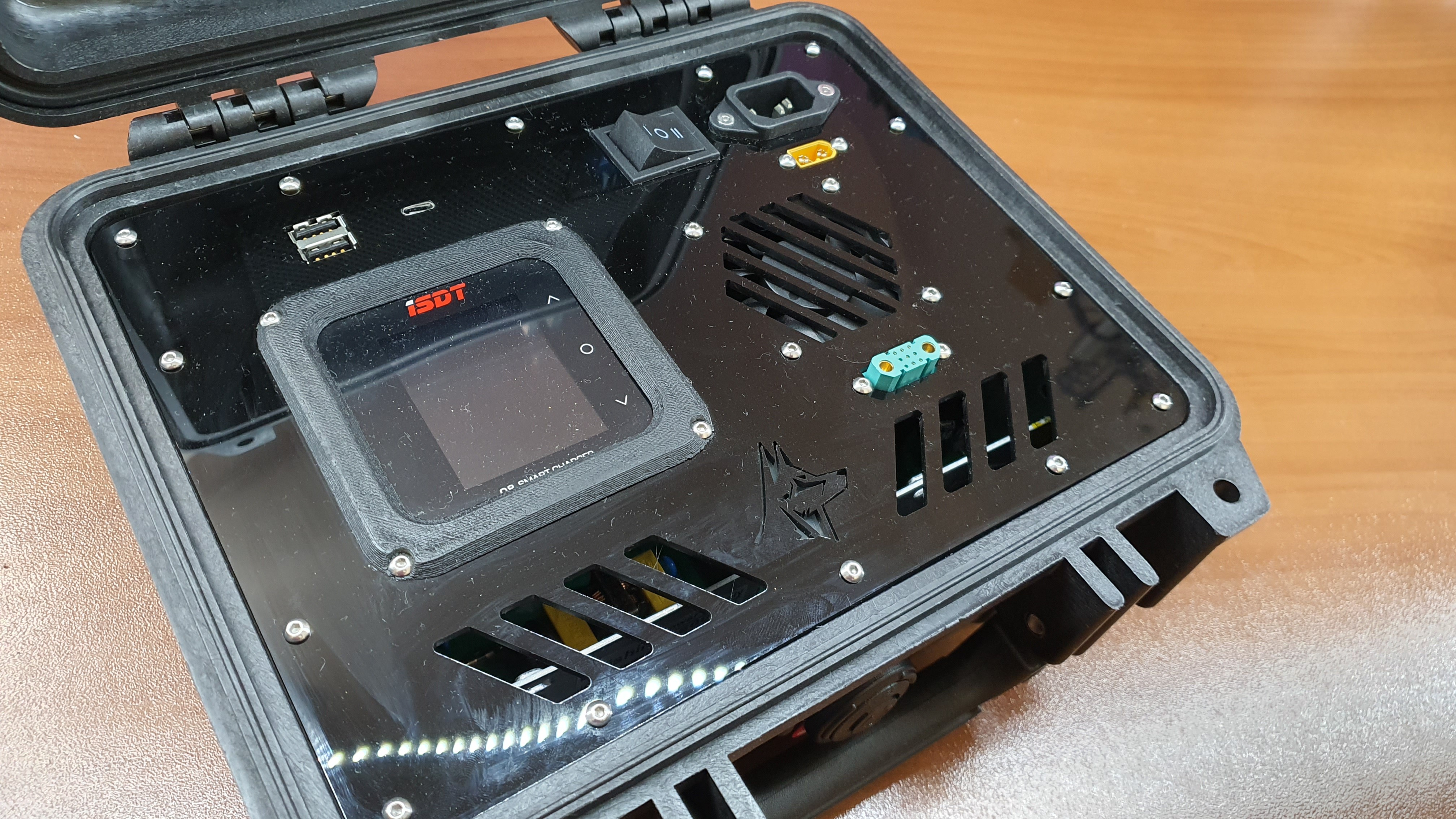
With V2, we decided to rely on a reputable charger, the ISDT Q8. Making reliable custom Li-Ion chargers, as learned from V1, is not a simple science, and relying on reputable commercial modules (not some cheap off-brand battery charger modules) made the most sense. To maintain a small rugged form factor, we built the charger into a pelican 1200 case. Overall for anyone familiar with drone battery balance charging, it's a pretty straightforward build. The power supply is all built into the charger, so any AC power source can plug directly into the unit. Thanks to the Q8's DC input, there's also an XT-60 DC input for other power sources. A manual switch allows you to select between either power source. One unique aspect of this charger box configuration is the single charge/balance port. Utilizing a JX-9 connector, we were able to cram in a high current-rated discharge port, and all nine balance and ground contacts needed in a single small form factor port.
![]()
View of Pelican 1200 case
![]()
View of charger assembly inside the case
![]()
Close-up view of charger assembly
Testing/Tuning Rig Build
Testing both statically and dynamically is the core of any drone development project. With Valor, we experimented with custom rigs to run validation tests from the comfort of our lab!
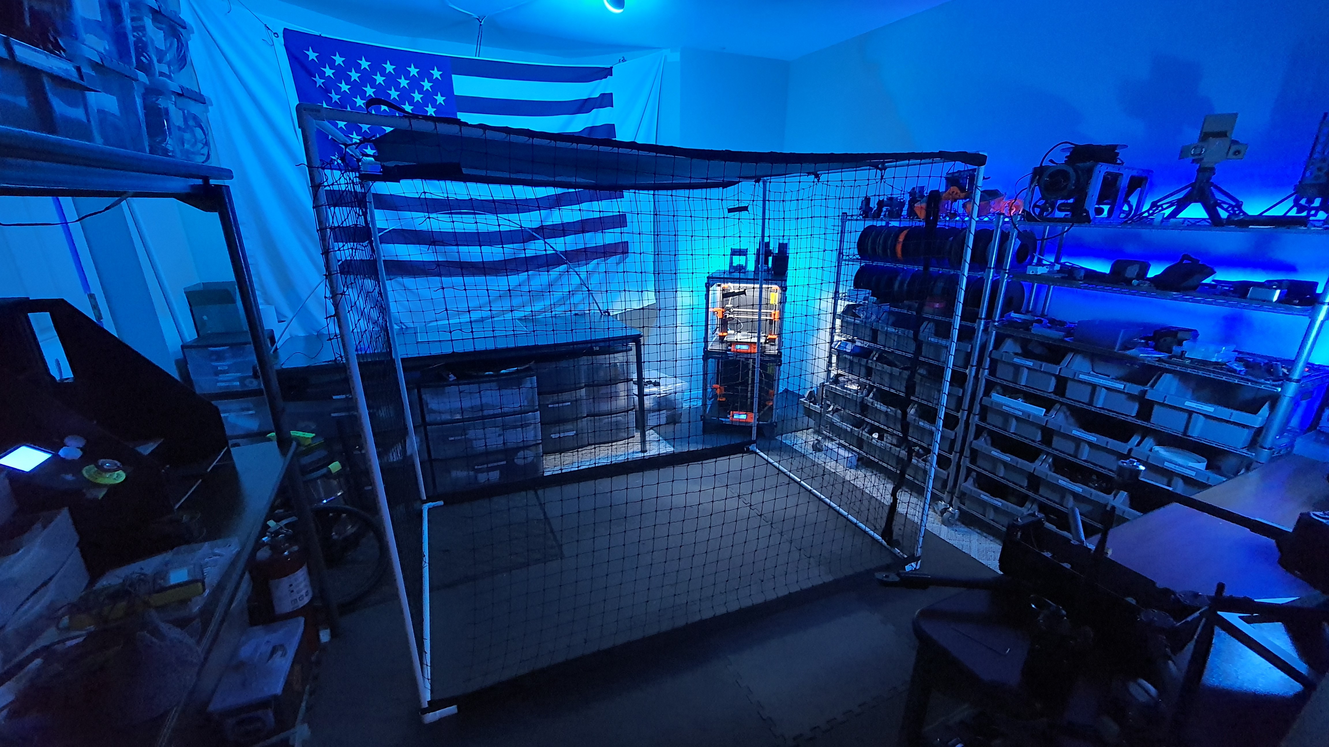
Flight Test Cage
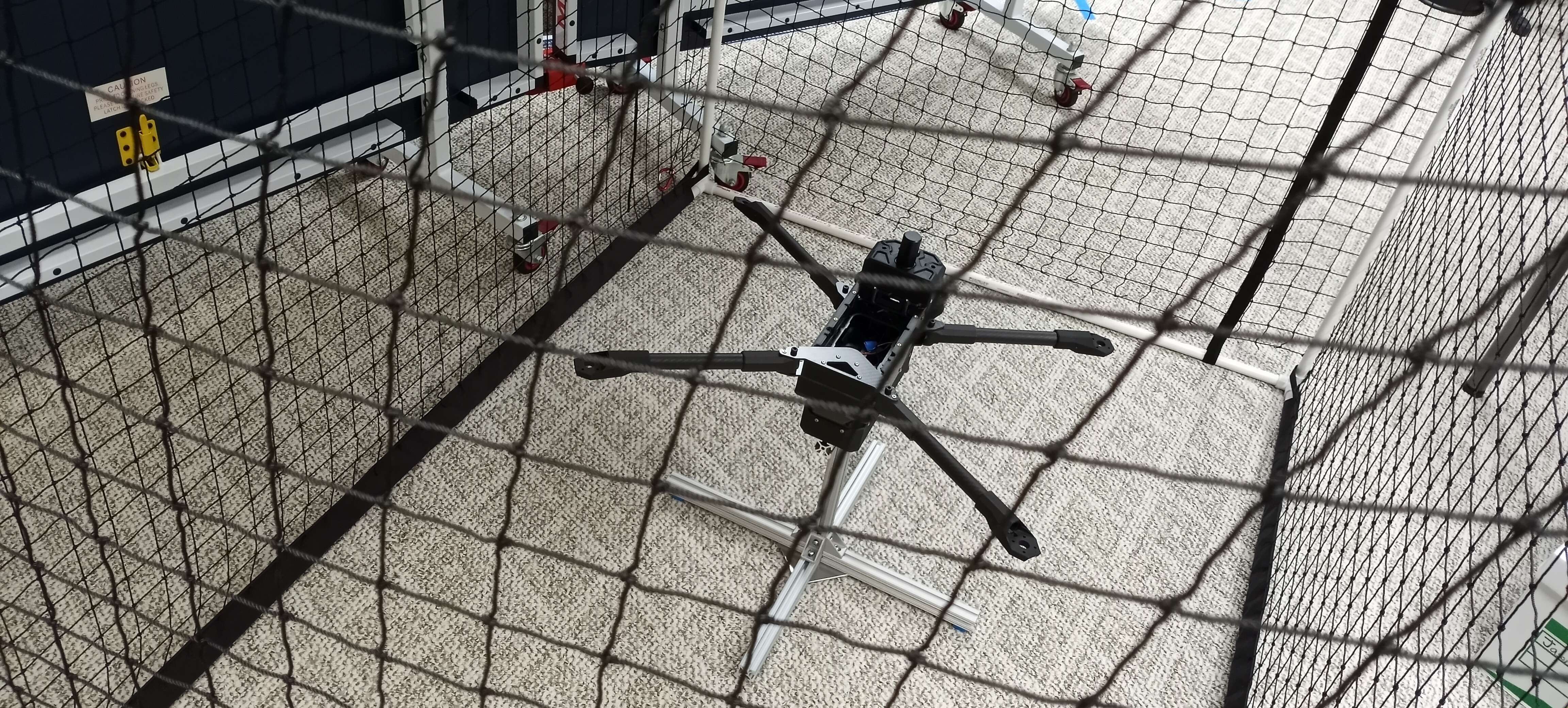
We used a PVC frame and sports netting to fabricate a custom flight test cage. This will allow us to provide some basic FOD protection during lab tests, do small hovers, and provide a flight test space for future mini UAV projects!
![]()
View of flight test cage in our lab
![]()
View of Valor UAV inside flight test cage for fitment checks
Test Stand
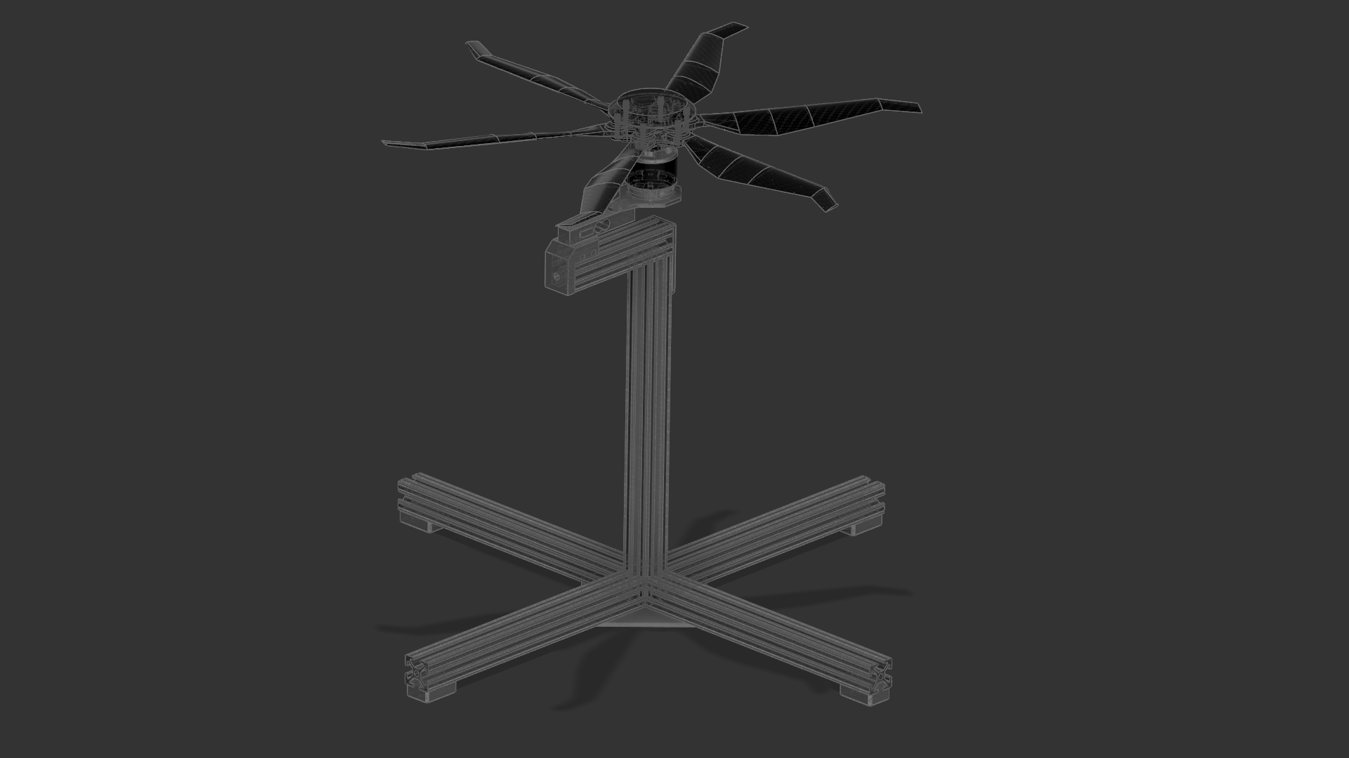
We wanted a multi-purpose test stand where we can test the entire drone and different motor and prop assemblies. We went with a 1010 aluminum frame maximizing modularity. With custom 3D printed fixtures, we can quickly mount the entire drone, specific components, or even a load cell, motor, and prop, and put them through various conditions in our flight test cage!
![]()
CAD view of the modular test stand
![]()
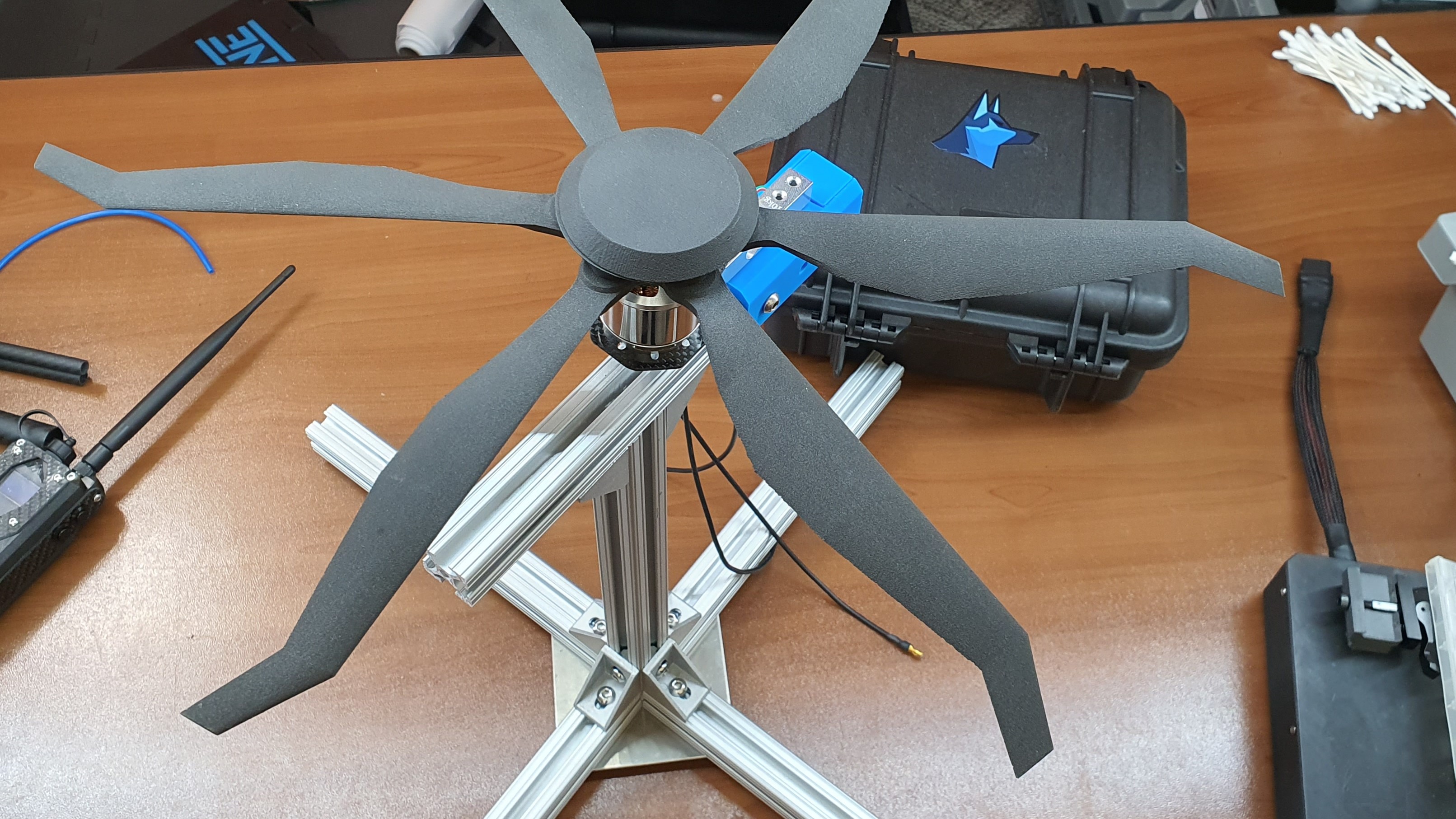
View of stealth prop on the test stand in its load cell configuration
-
Handheld Controller Development
12/23/2022 at 22:42 • 0 commentsDevelopment Overview
The handheld controller is one of the critical parts of the Valor sUAS ecosystem. It allows operators on the ground to take control of the UAV without the need for a bulky ground station. The role of the handheld controller is critical to understand, it isn't intended to carry out the full mission capabilities of Valor UAV, but rather offer basic control, live views of the camera, and some basic payload controls.
V1 Dev
The V1 controller was a really bulky and large design. Overall the ergonomics were decent, but the extremely wide geometry and bulky frame made it really heavy. It was manufactured with a 3D-printed shell that was skinned in carbon fiber for ruggedization. The overall goal with V1 was learning more about the control layout and feel.
![]()
View of CAD design of V1 controller
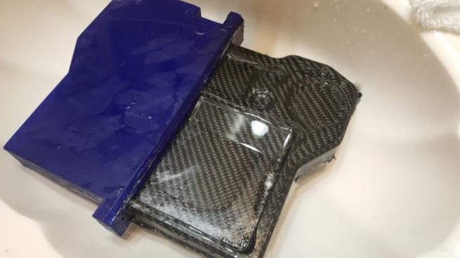
![]()
View of carbon fiber skinning process before epoxy binding
![]()
View of V1 controller after carbon fiber skinning and sanding
![]()
View of partially integrated V1 controller
*Since we got all that we needed to learn from the V1 controller, we didn't bother integrating components any further.
V2 Dev
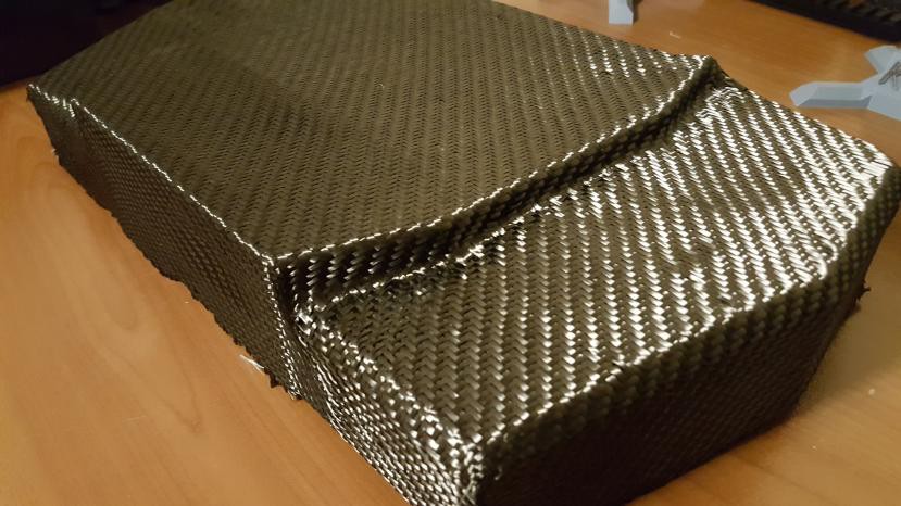
V2 was the first step into slimming down the entire device to a far more compact form factor and shedding off weight. There were two key differences; for one the joysticks were moved to the top of the display to reduce the width of the device, and secondly, the entire body was molded out of carbon fiber. The overall weight of the controller body was shockingly low. We were relatively happy with the design, except the ergonomics were pretty horrible. Having a very steep angled ledge from where the hands grip the joystick is very uncomfortable, and embarrassingly enough this is the primary reason v2 was scraped. The expensive lesson learned is making simple mock-up models of the handheld device first and rapidly prototyping them first, before designing the final model. From this point on all designs involving ergonomics, we always 3D print a simple mock-up to study the feel of the device.
![]()
View of CAD design of V2 controller
![]()
View during demolding of carbon fiber controller body
![]()
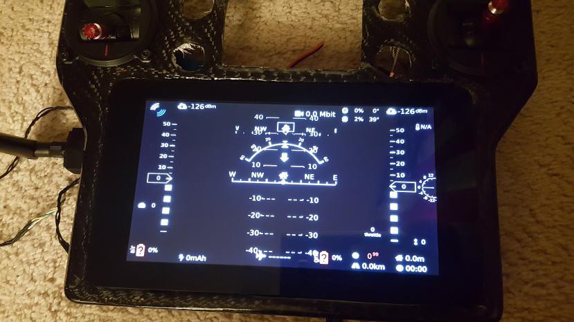
View of a quick test of electronics during integration
V3 Dev
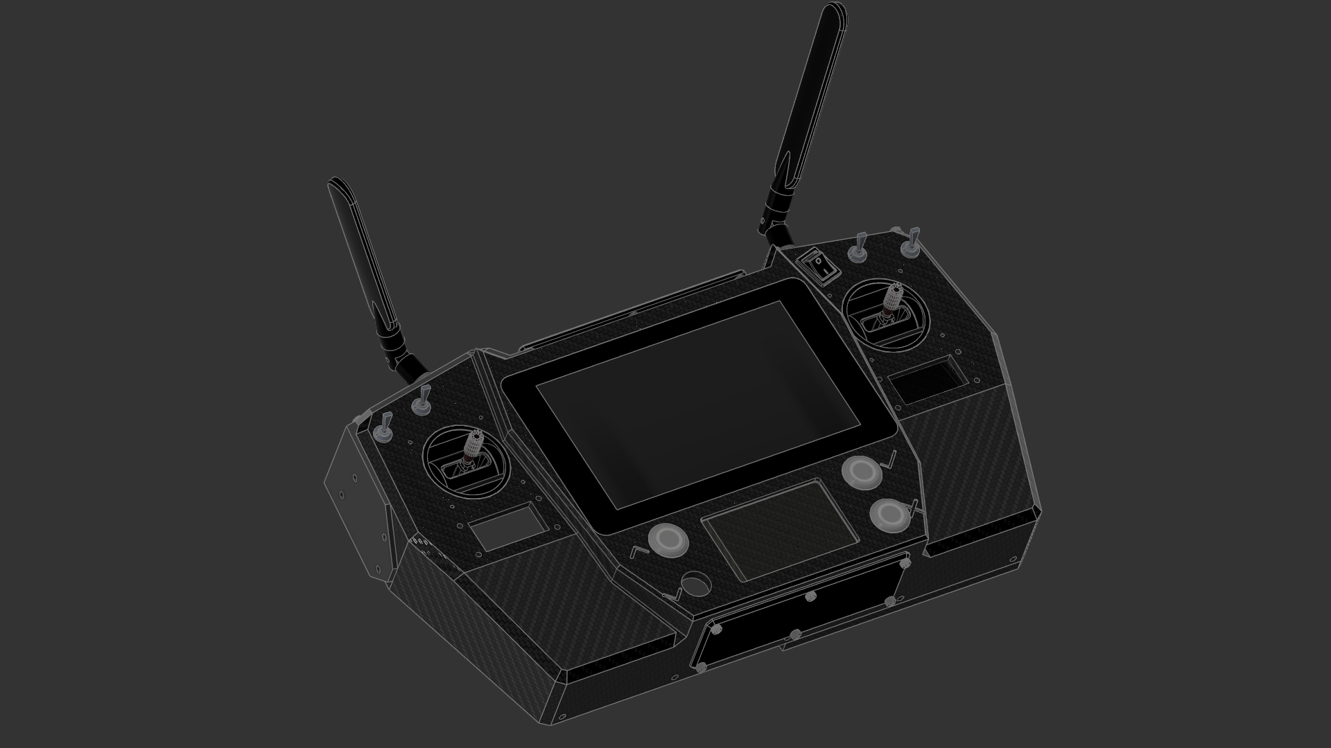
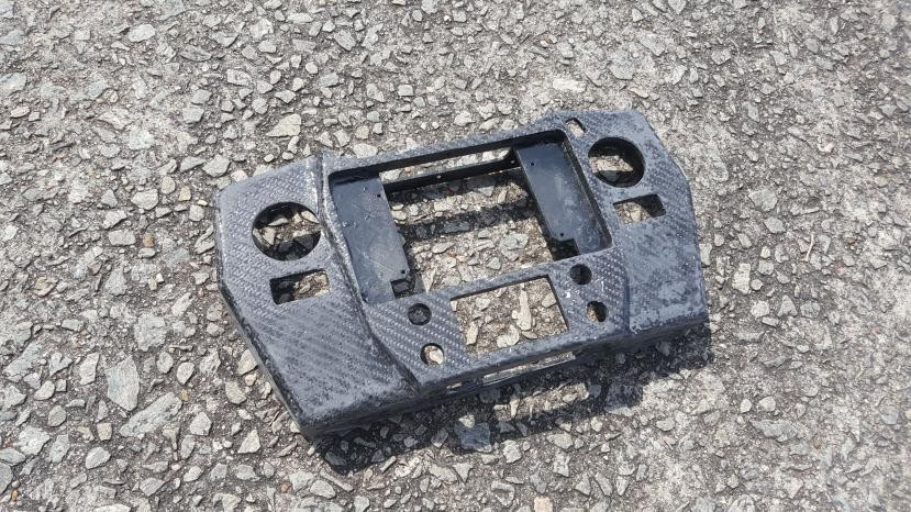
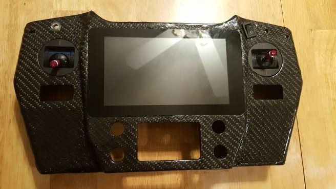
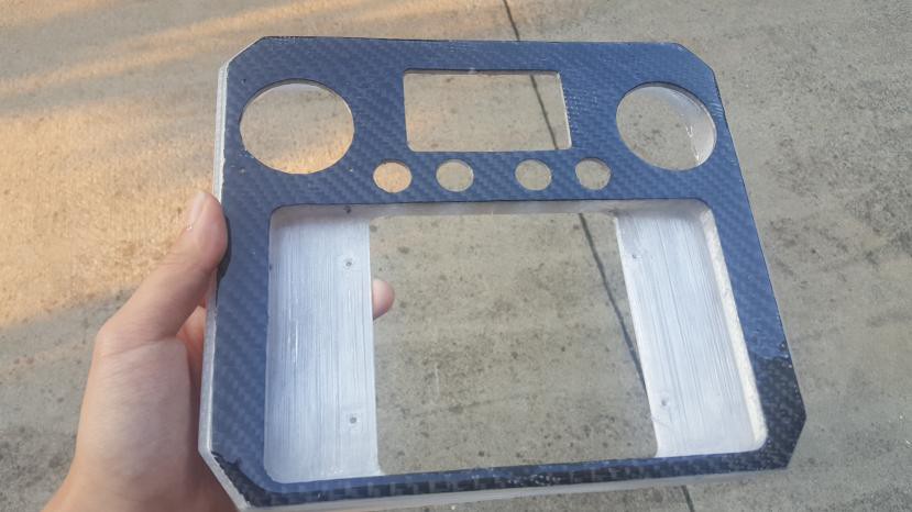
V3 was by far the best controller designer; the body was slim and light, everything was more compact, and we studied the feel via mockups before progressing with the model. This iteration took a hybrid approach to manufacturing. Both skinning and molding carbon fiber takes a lot of effort and time. On V3 the entire body is 3D printed, but a layer of carbon fiber is bonded to the front plate for added ruggedness. It came out to be the cleanest layup job by far.
![]()
View of CAD design of V3
![]()
View of the controller during carbon fiber layup
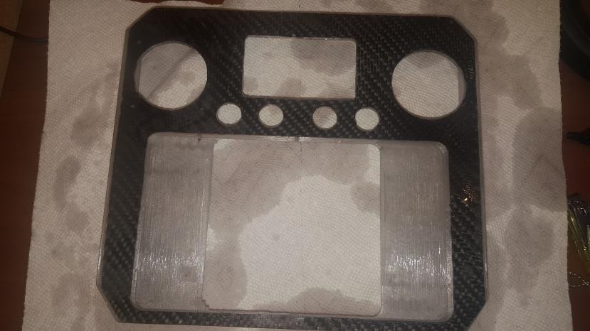
![]()
View of the controller after final polish and clear coat
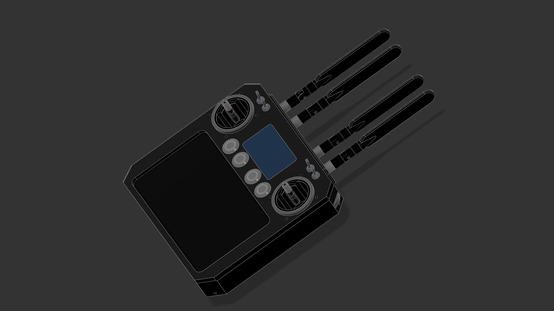
![]()
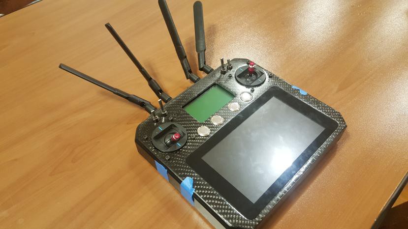
View of the controller after all the hardware was integrated (looks like a wifi router)
V4 Direction
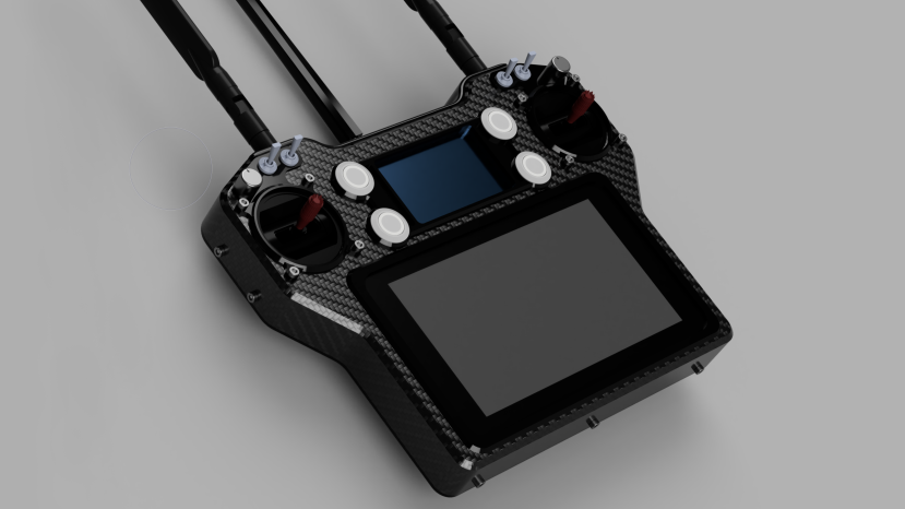
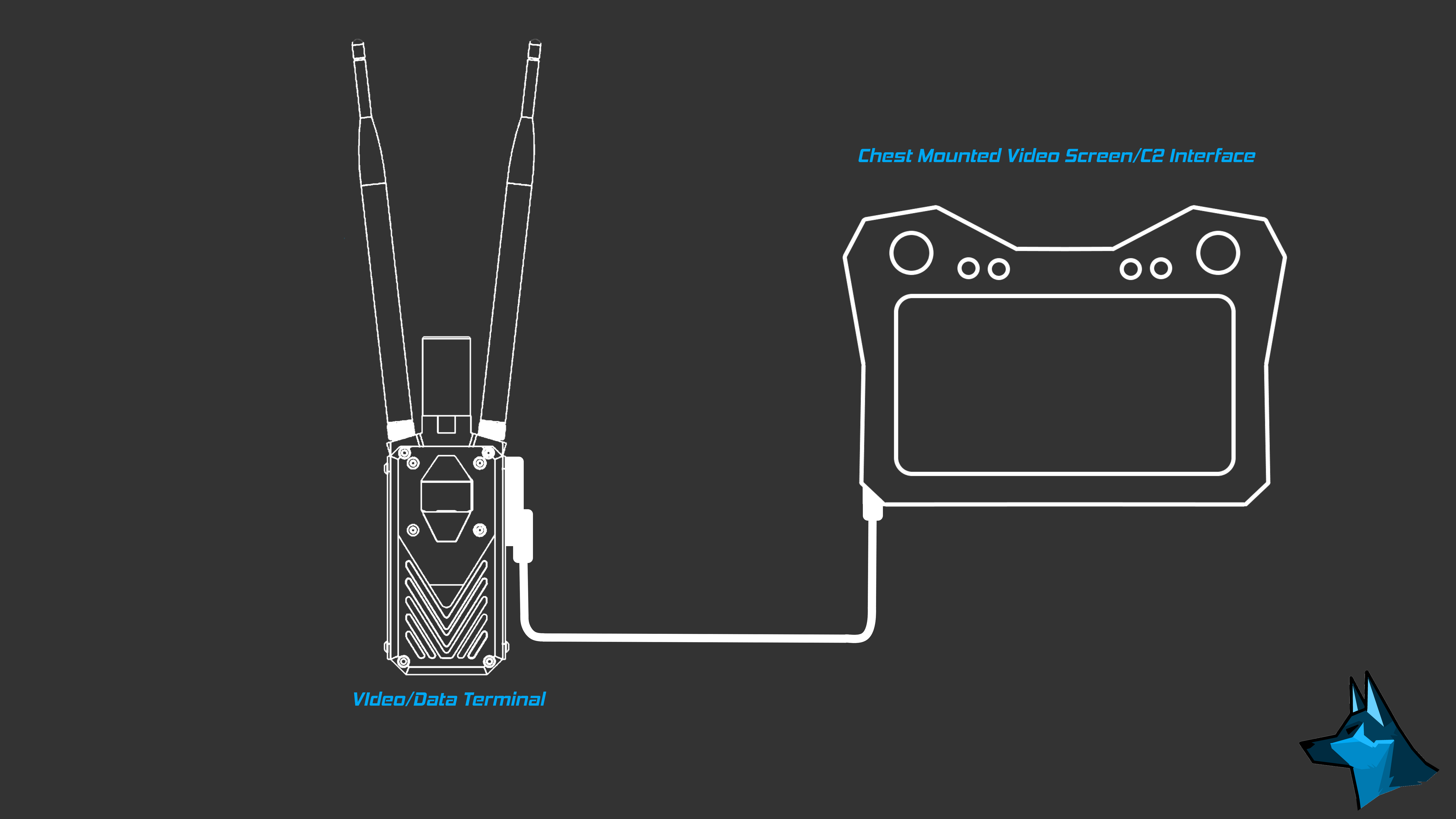
After three iterative prototypes, we learned one simple fact: For the intended users of Valor sUAS, the overall direction with the more handset approach was wrong. A handheld controller is relatively bulky, and the antenna orientation is not optimal in all circumstances. By looking at commercial options the obvious solution is to separate the radio module from the screen and joystick.
![]()
Quick concept mock-up: controller and radio module separated
For much more of a tactical configuration, it's common to mount the radio module to the back of a plate carrier and have the screen and joystick mounted on the chest.
![]()
Quick concept mock-up: controller and radio module together
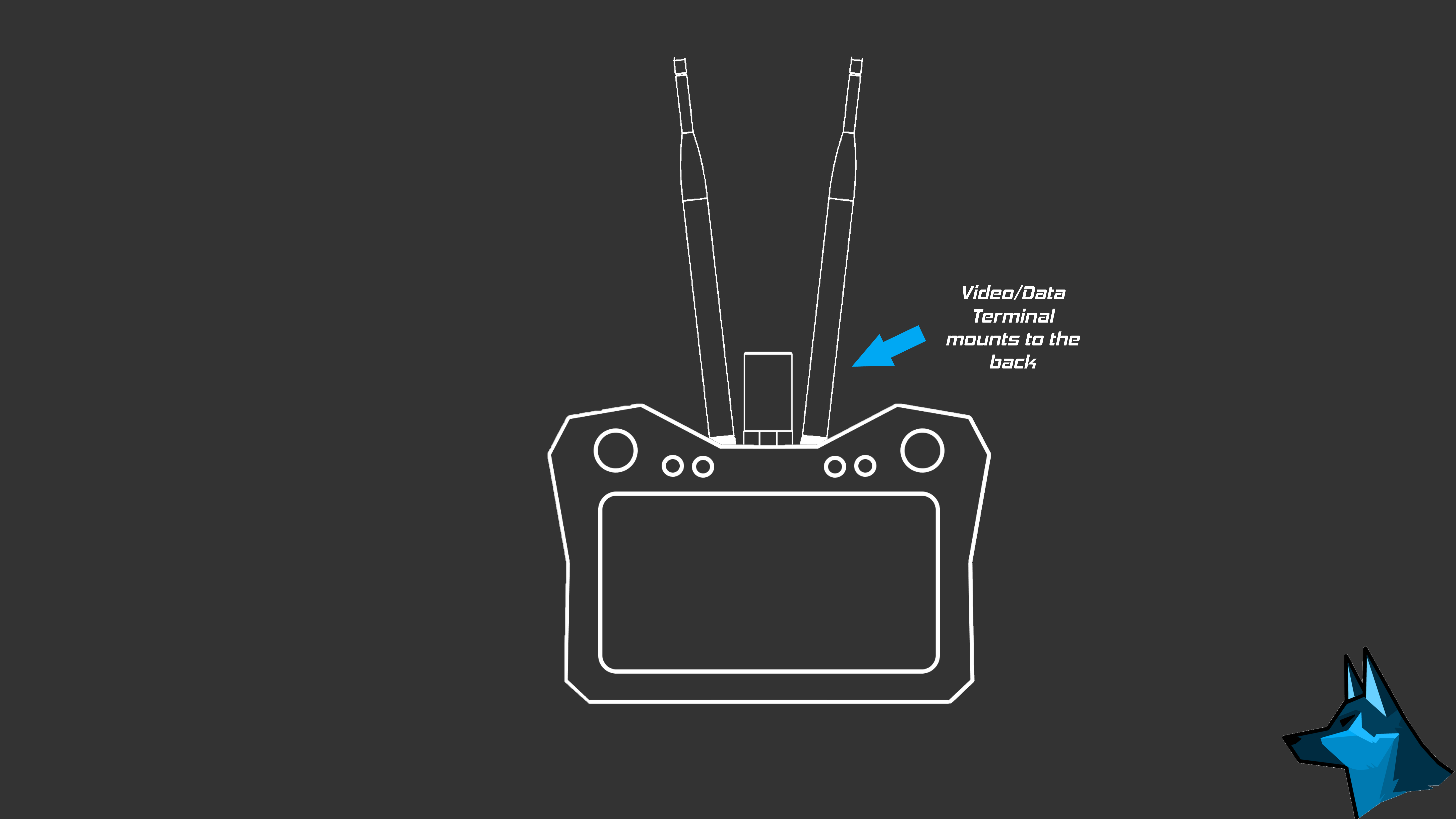
For applications such as search and rescue, however, having an all-in-one handheld controller may be more practical. The concept we came up with is the ability to mount the radio module terminal to the back of the controller via a custom modular port. By doing this we keep the system interactable with a variety of applications and adhere to the modularity concept the entire project is built upon. All in all, this is the direction we're confidently pursuing.
-
SPOT Optic Pod Assembly
12/21/2022 at 22:12 • 0 commentsGimbal/Enclosure Assembly & Starlight Electro Optic Dev
The gimbal-stabilized enclosure pod is the heart of the ISR part of Valor sUAS. Building a gimbal isn't too tricky nowadays with great open-sourced gimbal controllers and a wide selection of motors, which we made sure to take full advantage of. The next challenge was building a weatherproof and aerodynamic pod to compactly cram in multiple optics. The optics pod enclosure had the most amount of full revisions in CAD out of any assembly we designed for Valor sUAS, with development on the SPOT dating back to 2020, but we managed to cook up a very good geometry and intuitive assembly to make integration and tuning a breeze.
One of the challenges we faced was miniaturizing the optic pod. To provide operators with an effective and practical FPV feed, the ISR package needs to be able to zoom into a subject. Initially we looked at large zoom camera modules that required heavy lenses and a large overall dimension. This would mean to achieve the same mass/form factor budget for the SPOT optic pod, the laser and thermal camera could not be added as part of the package. The solution we came up with was what modern phones have adopted, taking advantage of multiple lenses and sensors to effectively create a hybrid zoom! By using 2 sets of optics and sensors with carefully selected focal lengths, we ran multiple bench tests to create the best combination till we reached an insane range of 170 degrees if wide angle camera feed to 30x zoom equivalent maximum zoom. With 2 tiny cameras and lenses, we effectively reached an equivalent performance of most medium size fixed wing ISR drone optics!
![]()
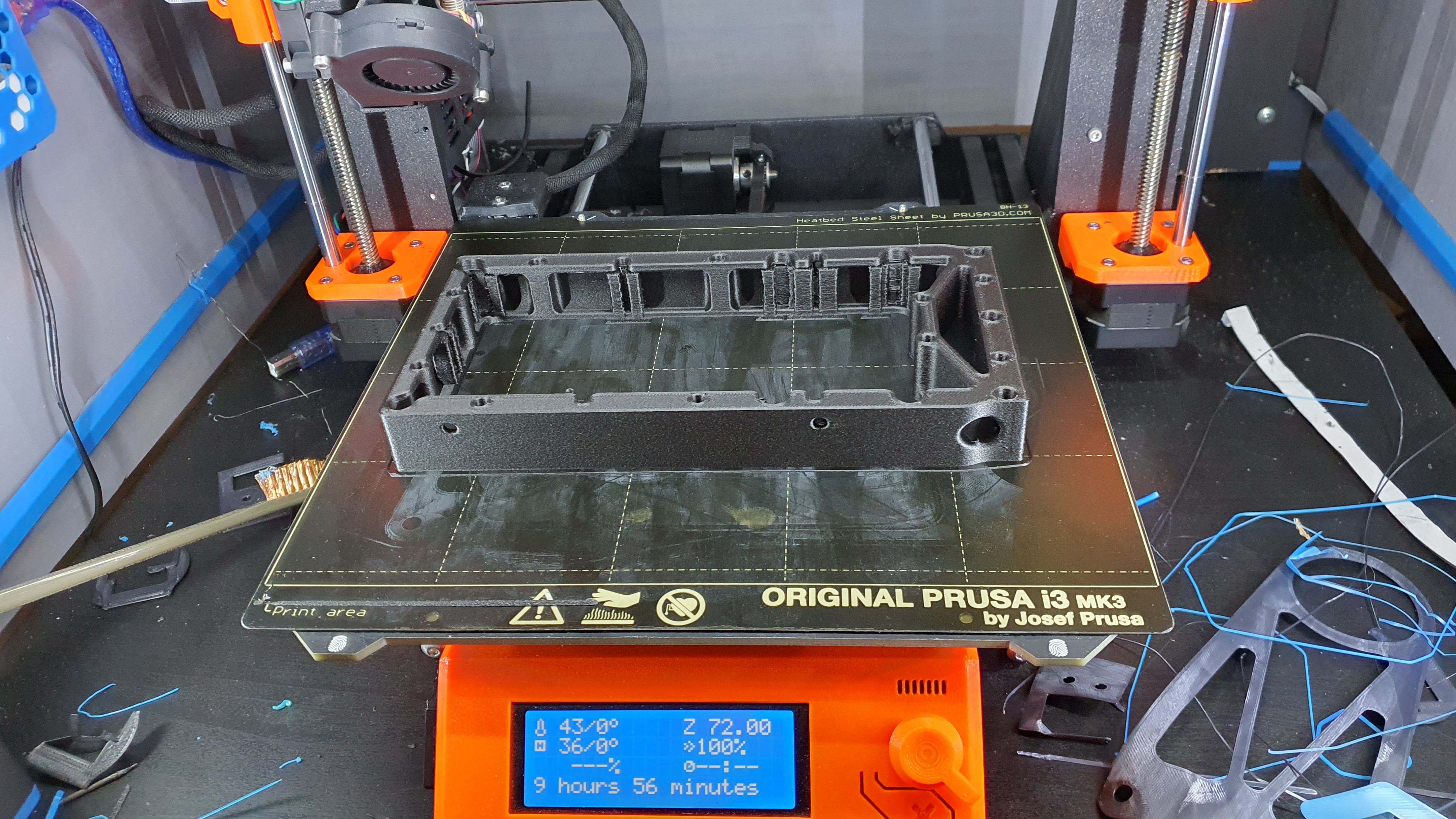
3D Printing the prototype enclosure pod. The final version is SLS 3D printed.
The enclosure is a 3D-printed sealed pod that houses all the electronics. The prototypes are FDM 3D printed, however, the final version is SLS 3D printed with a waterproof coating. FDM 3D printing is not watertight, which is problematic for an optic enclosure, we really don't want condensation or any moisture overall.
![]()
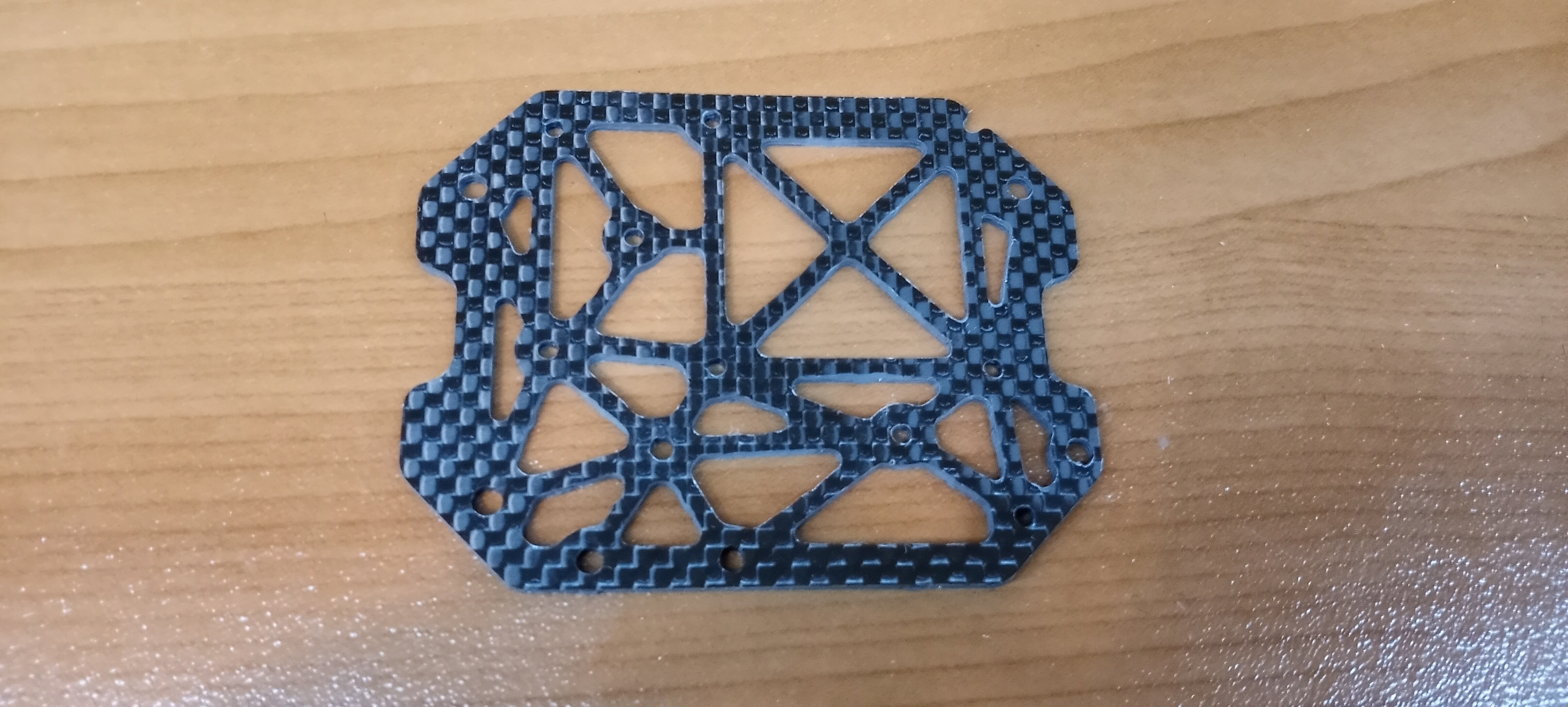
View of machined optical frame
![]()
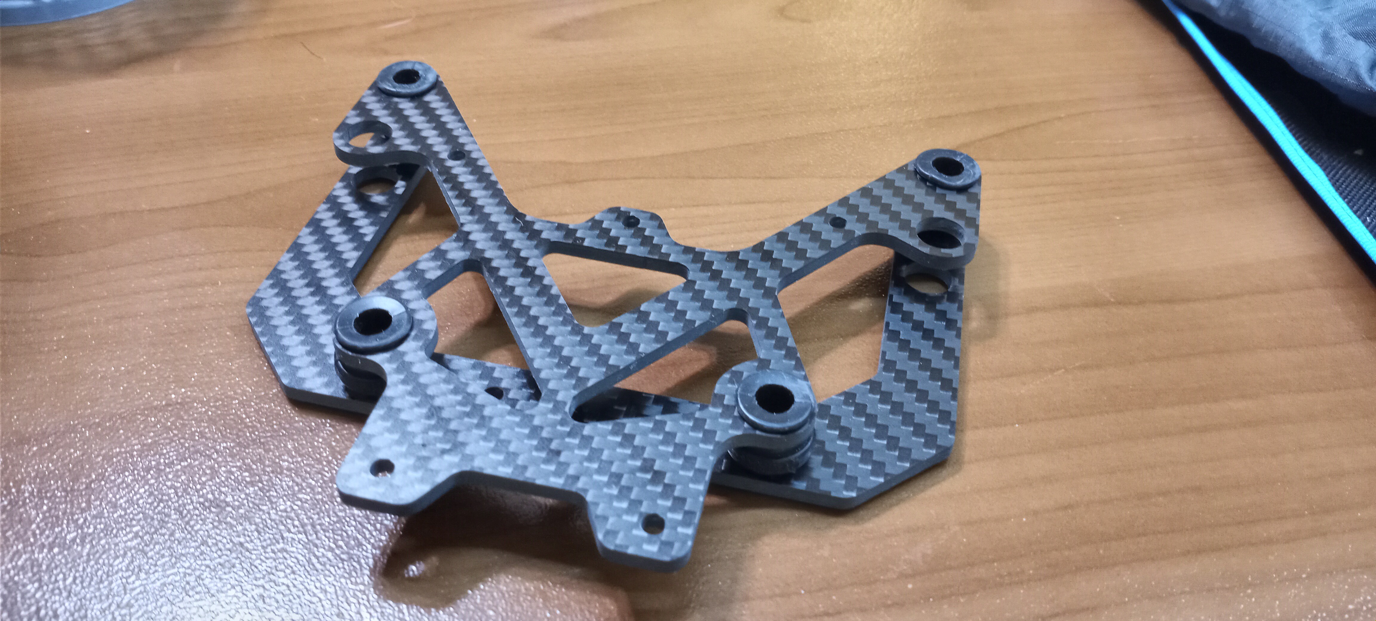
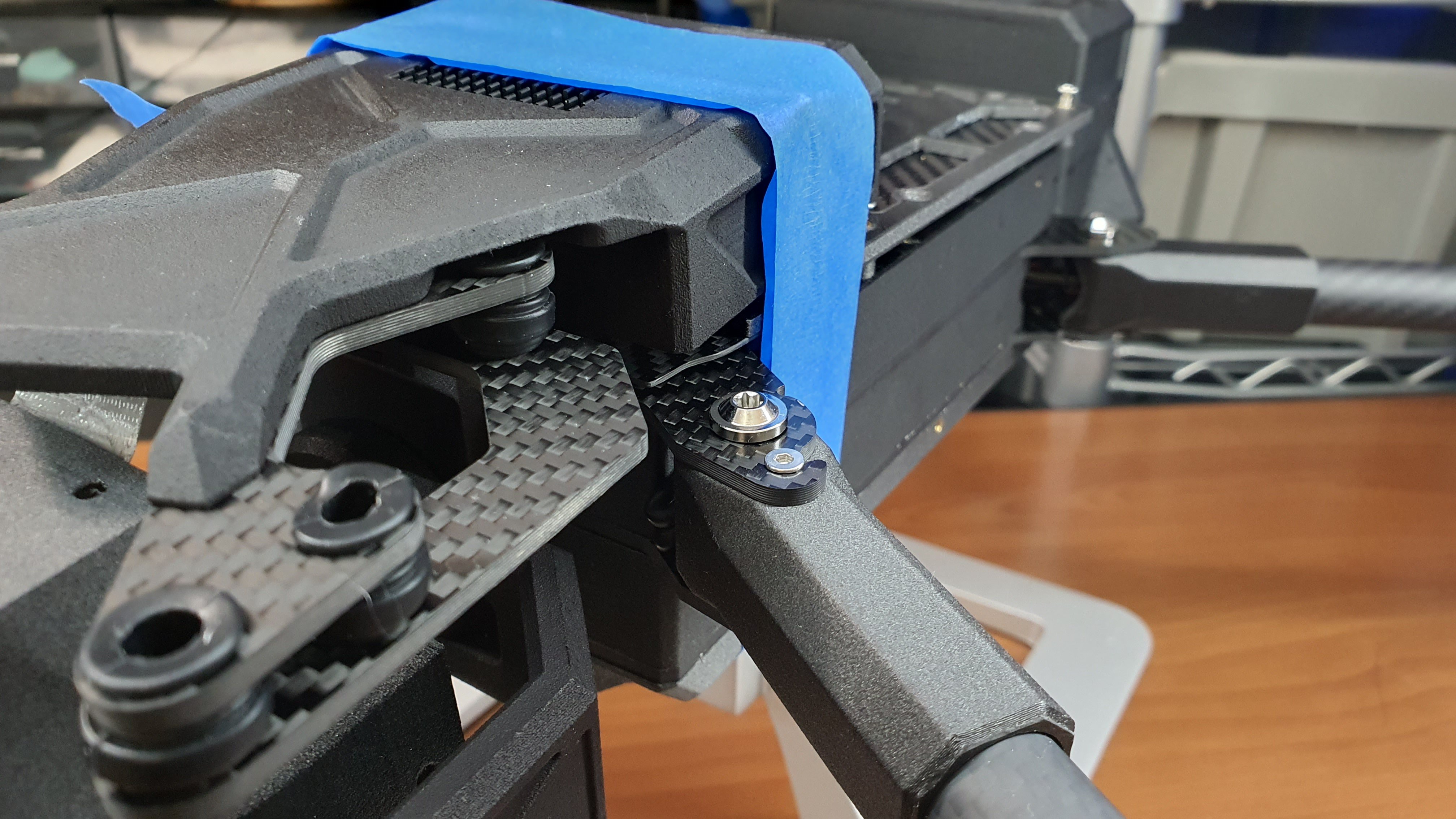
View of vibration dampener assembly
![]()
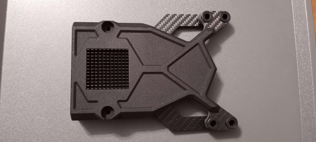
View of electronics enclosure and vibration dampener assembly
Like the airframe, carbon fiber was the material of choice for most of the gimbal's structural components for its superior strength-to-weight ratio. The vibration dampener isolating the optic pod from the vehicle interface is a critical component in preventing video jitter. For this application, carbon fiber, a material with very high stiffness properties is preferred to prevent resonance.
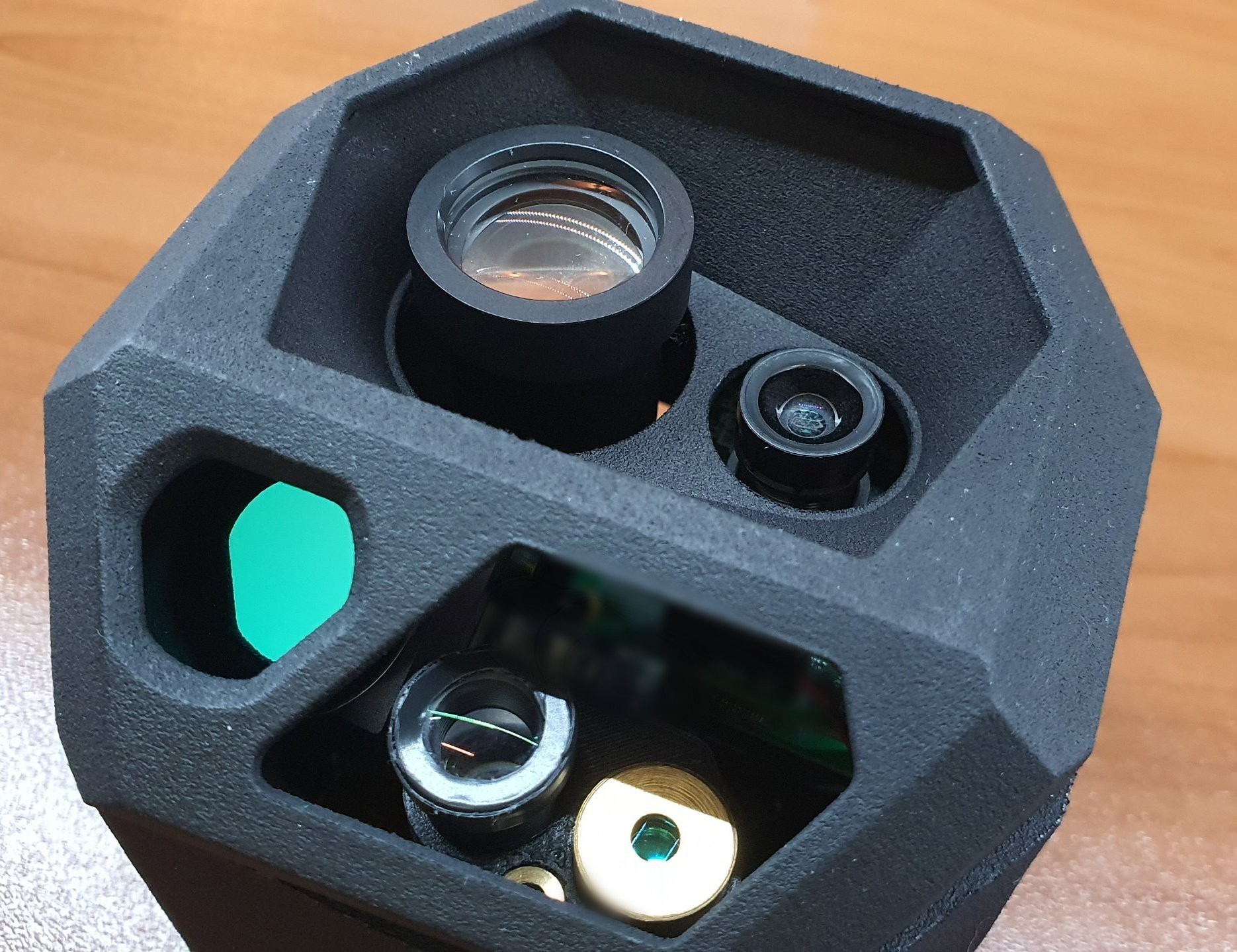
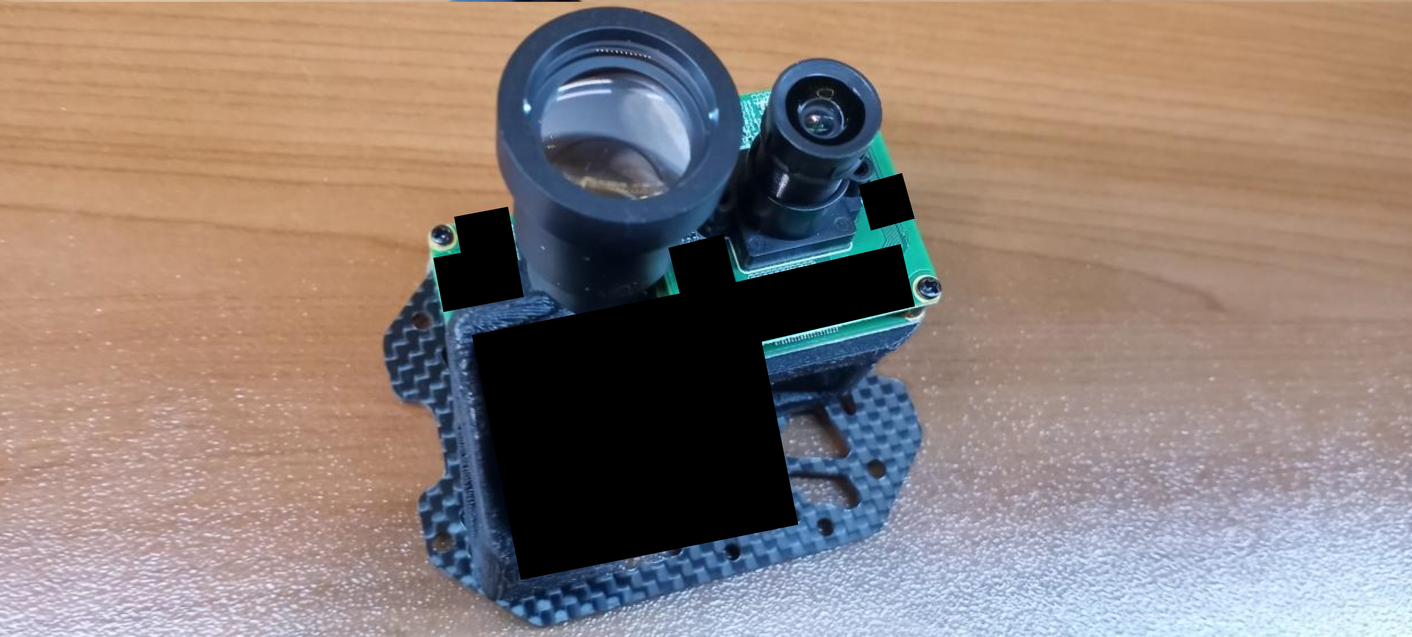
A lot of optics pods seem to have the optics built into the enclosure. We did the opposite by building the enclosure around the optics. This means if the optics need to be removed for maintenance, it slides out of their slots with the removal of only four screws. The carbon fiber optics frame holds everything together in one piece, so lenses can be easily swapped out and changed, any kind of tuning or even swapping the sensors requires minimal tools (Only an allen wrench).
![]()
View of EO/IR assembly mounted on the optic frame
![]()
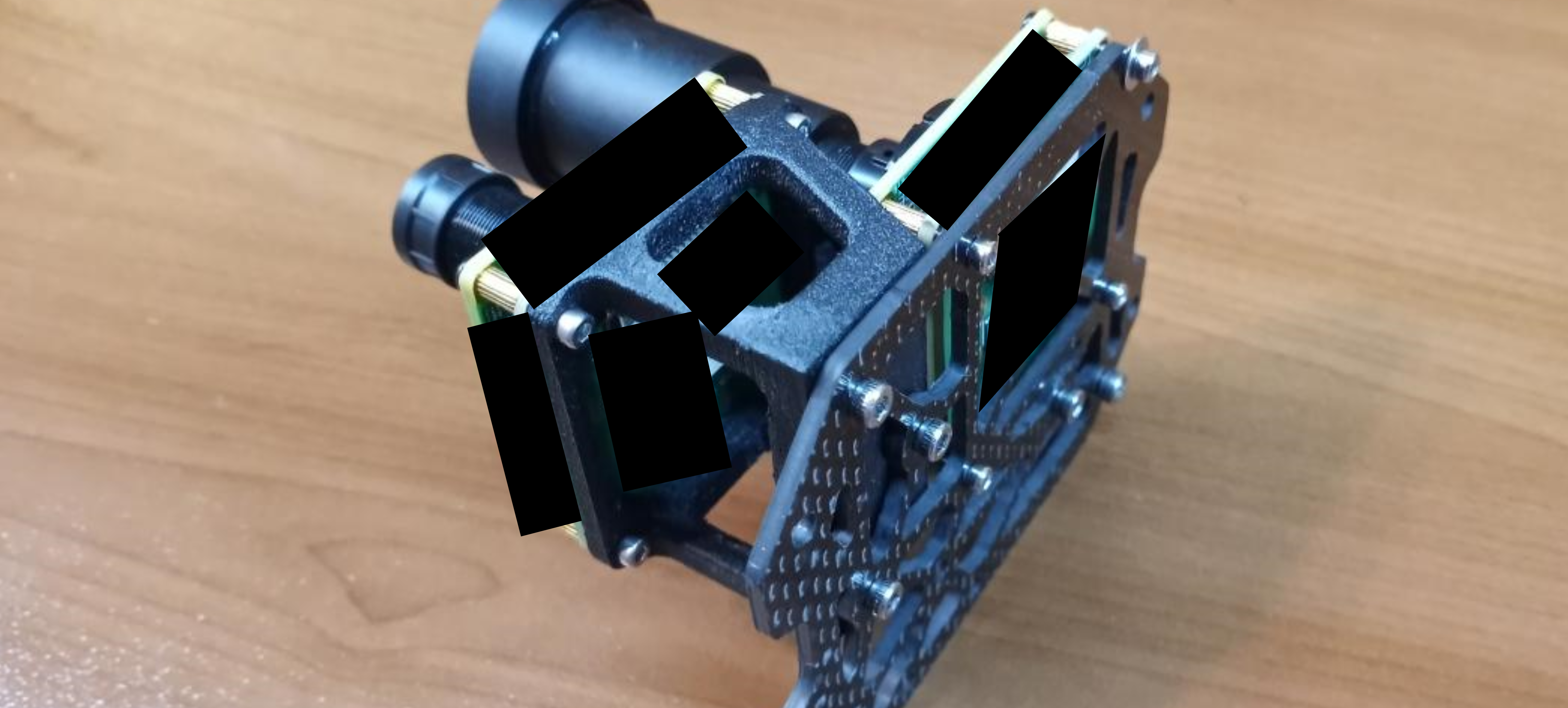
Side view of EO/IR assembly mounted on the optic frame
![]()
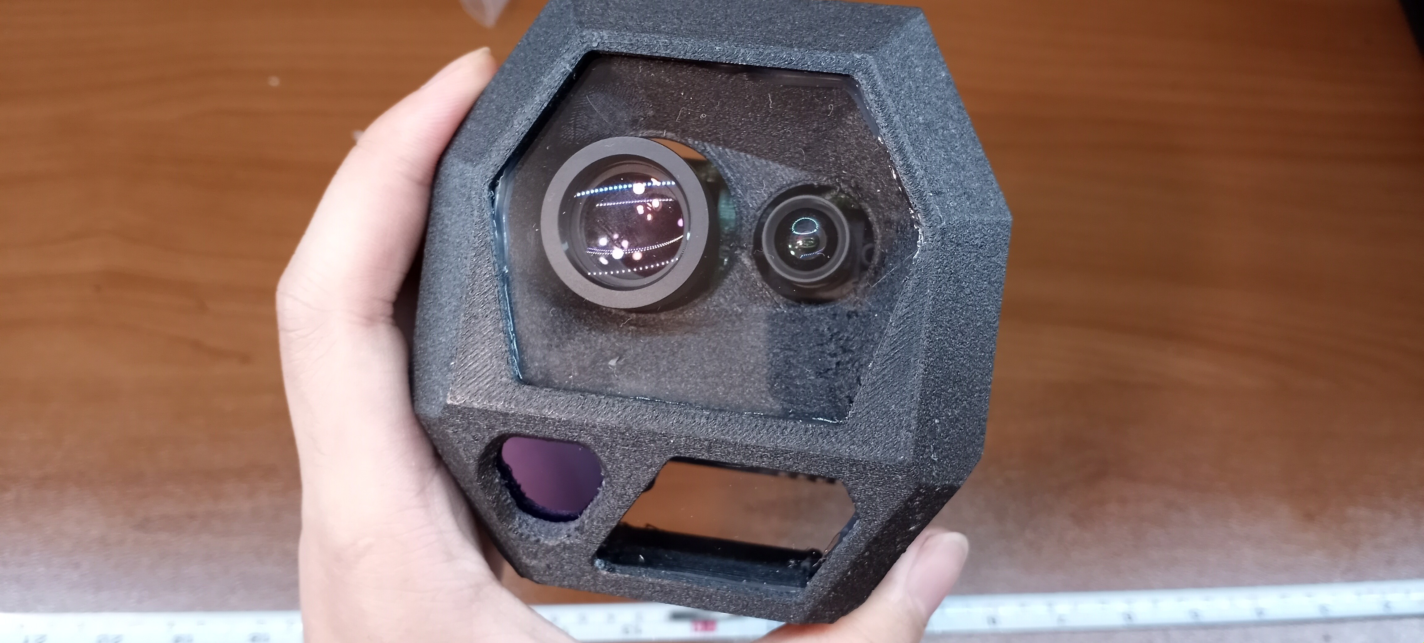
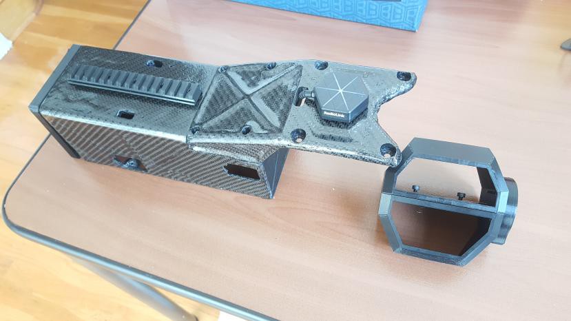
SPOT Optic pod after integration, laser assembly not installed yet
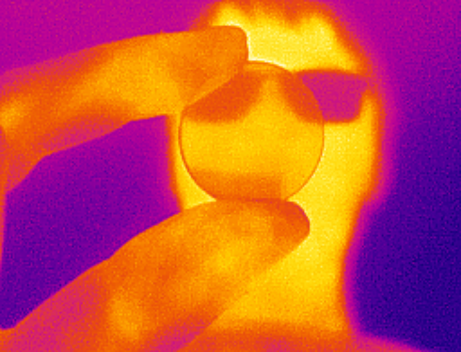
The enclosure pod acts as a frame holding the Lexan optic windows and the germanium window. Thermal cameras can not see through glass or Lexan, so a special optical-grade germanium window needs to be used. Germanium is like the opposite of glass, completely blocking all visible light and only letting IR through. It looks like a metal disk
![]()
Demonstration of Germanium window and its LWIR transparent property
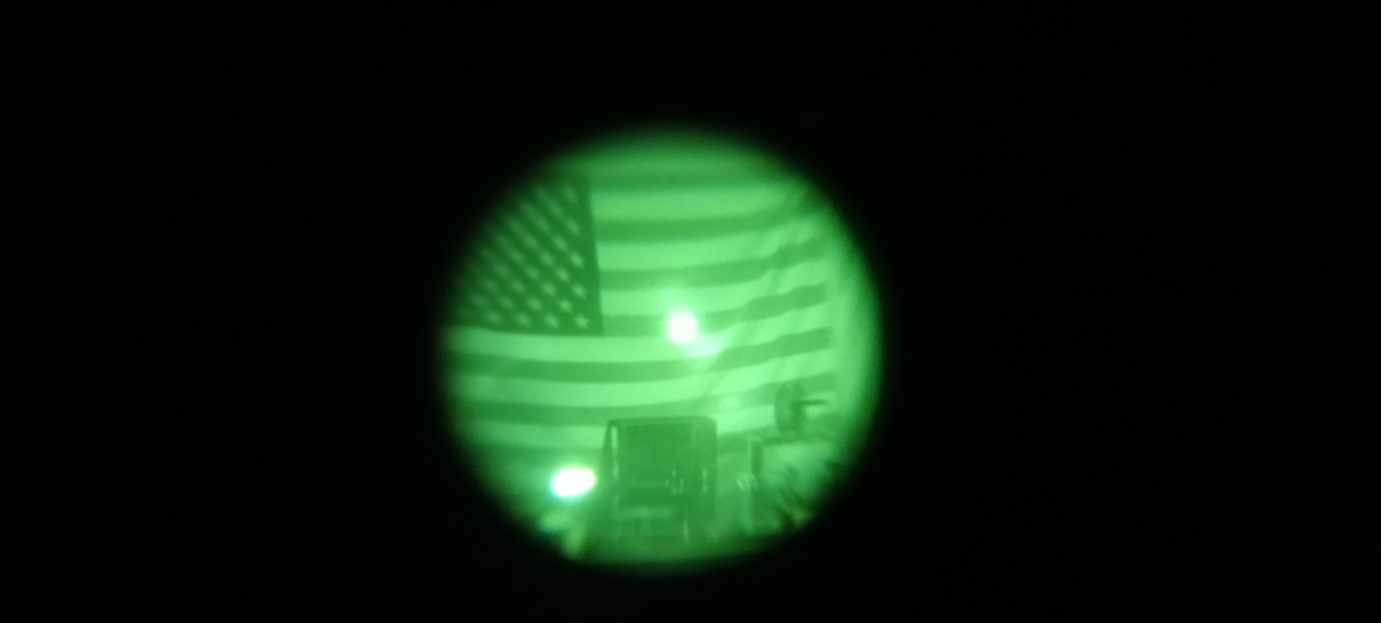
After integration, we proceeded to test the thermal optics and the electro-optics. Details on the thermal optics can be seen below. The visible electro-optic camera sensors were carefully chosen starlight sensors, offering incredible low-light performance on par with commercial digital night vision. We were blown away by the low light sensitivity of our sensor!
![]()
Our lab serves as a simulated low-light demo. Exposure and clarity increased to match what the human eye could see
![]()
What EO sensor on SPOT could see, notice HUD view. Absolutely incredible low-light performance!
*Just to give you a perspective, the red glare on the right side of the image is a tiny red status light from a microcontroller that's barely visible.
Thermal Electro Optic Dev
Thermal optics is a must on any effective ISR platform. A thermal camera allows us to see in the infrared spectrum making subjects of interest such as people quite literally glow in the dark. Because the mass budget is very tight on the SPOT optic pod, the visible electro-optics were prioritized over thermal. In this platform, the small LWIR thermal sensor will serve as a detection role while the visible sensors will serve as the identification role.
We carefully selected a thermal camera that was small enough to fit into SPOT, gave a decent resolution, and most importantly provided an effective refresh rate (Most sensors are locked at 9hertz to be easily exportable). Afterward, we looked into various germanium optics. The current sensor we selected has the option to swap out between a wide angle and narrow view lens, and even with the wide view lens, it demonstrates exceptionally amazing performance as can be observed below!
![]()
Private Jet about 1.5km away at night
![]()
Group of people 75 meters away
For those unfamiliar with thermal cameras, the resolution of these sensors doesn't need to be very high to serve their roles in detection. The best analogy is the "heat radar", you need just enough resolution to detect and know what it's looking at. An important metric especially for a drone payload is DRI or Detection, Recognition, and Identification. Using pixel counts and different user feedback, we conducted various tests in various environments to test the effective DRI of our optic. We were shocked at the result from our sensor with a wide-angle lens :
![]()
DRI Test on a hot day at the beach. The camera picked up a person 1.2km away on a warm day!
Keep in mind that with our narrow-view lens it would perform even better which we, unfortunately, forgot to take on our beach trip (SPOT can easily accommodate bigger lenses thanks to its modularity). Out of all the tests we've conducted, this is one of our favorite ones to show, as you can tell from the ambient temperature, it was a pretty warm day! Even then it demonstrated effective DRI resolution to pick up a person at 1.2km away. In the future when we implement computer vision and an on-the-edge video processing SBC onto SPOT (It already has the expansion ports for it built in!) It could easily notify the operator of what is being detected.
Laser Designator/Illuminator Dev
We like to call this part of the project the "Flying Peq-15", since it literally has the same features and capabilities. This is the part of SPOT we are taking the slowest due to the inherent risk. IR lasers are completely invisible to the naked eye, and the power levels we're working with is enough to instantly blind you. The designator lasers, both visible and IR, are rated for 5mw, the highest limit considered eye safe. The Illuminator however holds a much more powerful laser that could easily instantly blind you at close range. Because the beam is but through a beam expander, at long ranges there isn't enough concentrated energy to hurt your eyes. But by no means should it be neglected or treated as a toy! The parts are already designed and being tested, however, the most challenging part is making a reliable system that can be entrusted with powering on such a powerful device remotely. You can see some of our tests below:
![]()
Proof of concept test prototype using cheap off the shelf laser
![]()
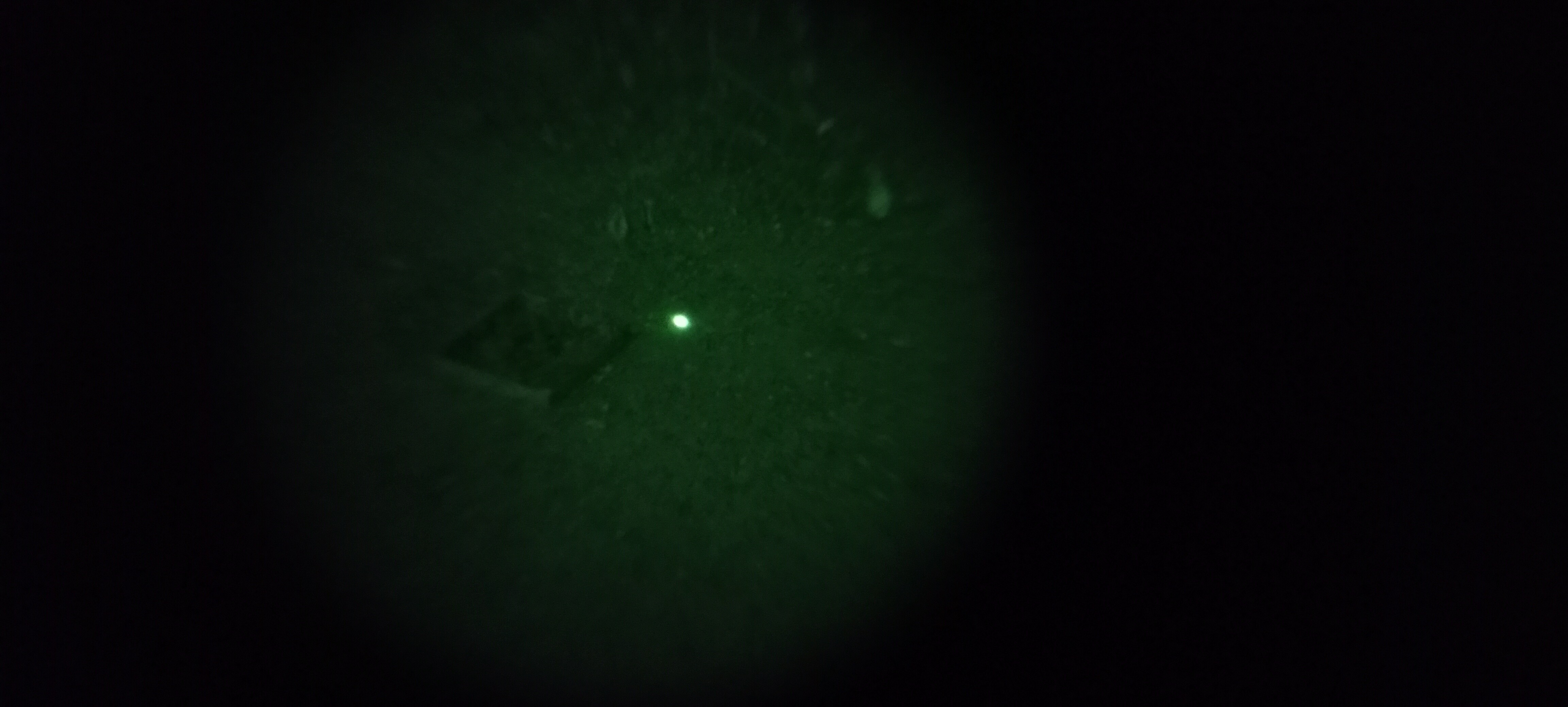
Night vision view of IR laser indoors
![]()
Night vision view of IR laser outdoors
![]()
Vis laser test outdoors, beam easily visible via low light cameras
-
Stealth Rotor Blade Development
12/21/2022 at 17:28 • 0 commentsStealth Rotor Blade R&D
The big part of Valor that gives its "Stealth" title is the optional stealth rotor blades! Drones are very loud creating a very distinctive buzz or whine that's easily audible and recognizable. Making a virtually silent drone is nearly impossible, at least with a quadcopter configuration. However, reducing the travel distance of the sound and masking the pitch closer to background noises is relatively straightforward. The exact methodology behind the R&D work for these blades can't be discussed in detail, but to the more technical individuals, you may have noticed some telltale details right off the bat ;)
Aerodynamics can be simulated, but until you test you simply don't know. The development of the blades involved rigorous amounts of test stand time, measuring power draw, RPM, thrust, and of course most importantly acoustics. We've taken advantage of 3D-printed props (Using SLS printers) to allow a very rapid data-driven evolutionary cycle of each version. It's more than strong enough for testing, but the final version will be made of carbon fiber.
![]()
Early spectrogram analysis of motor acoustic profile (as a control)
![]()
Early carbon fiber prop prototype
![]()
Early dev prototype, fully FDM 3D printed (It actually survived full RPM but it was terrifying!)
![]()
View of blade mounted on the test stand
*It's on our worktable for maintenance, all tests were conducted in a test cage
![]()
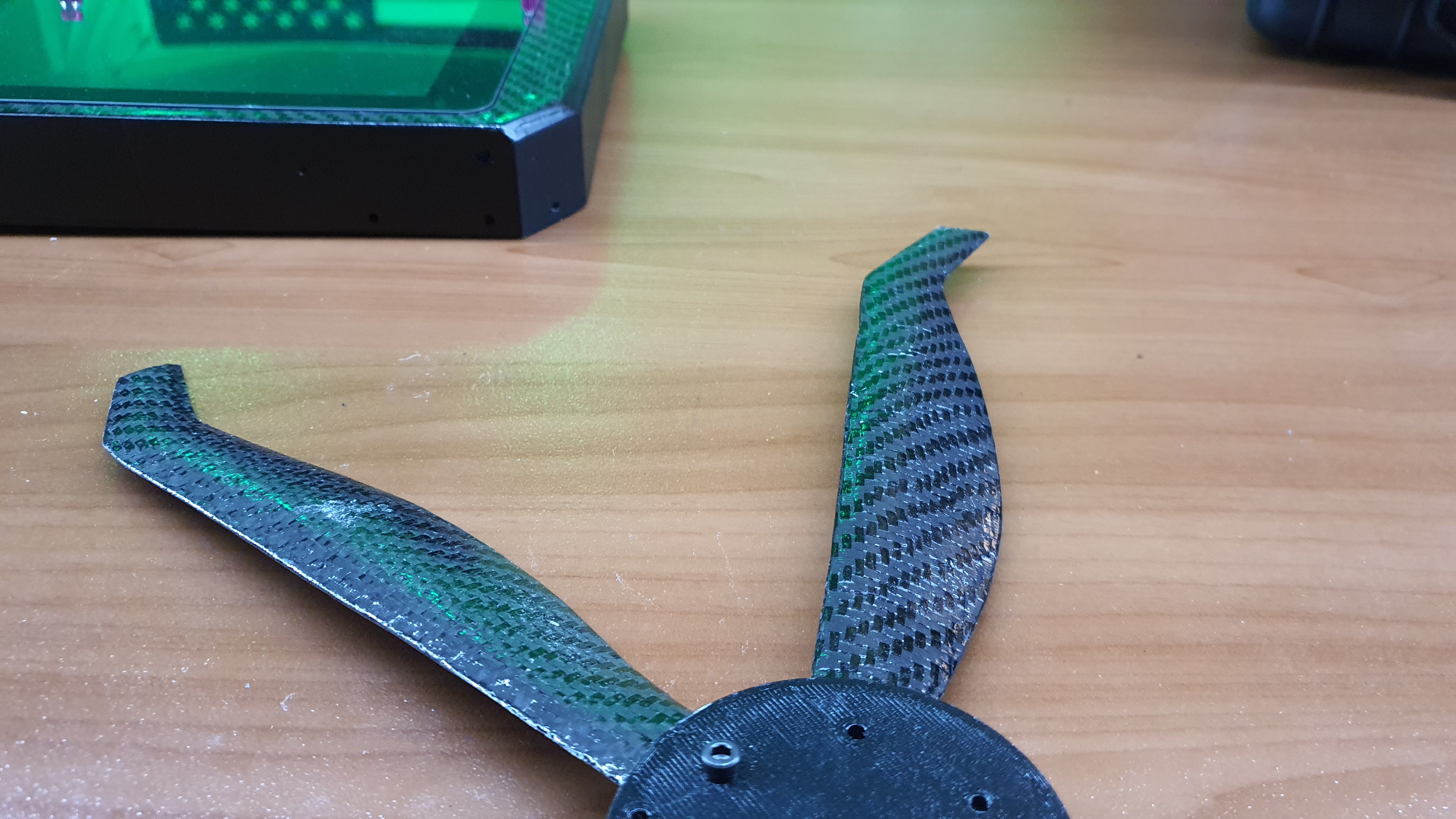
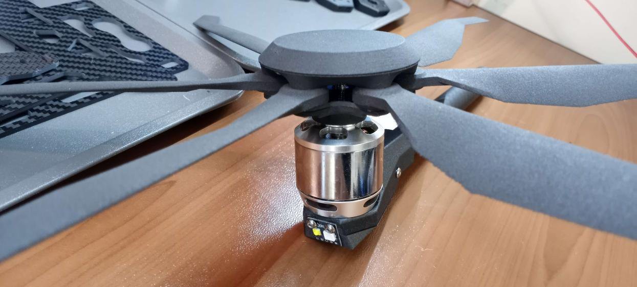
View of stealth blade prototype not mounted on a motor
![]()
View of stealth blade integrated into motor mount assembly
-
Electronics Integration & Build: Batteries, Avionics, and More
12/18/2022 at 04:07 • 0 commentsLi-Ion Flight Batteries
Flight time is a very critical requirement for this project. Typically Li-Po batteries dominate the drone power space due to their ability to discharge very high currents. However, Li-Ion battery cells (Popularized by Tesla's use in electric cars) are inherently able to carry far more battery capacity for the same weight compared to Li-Po cells. The only disadvantage is they can not output the same amount of current as Li-Po cells. There are new higher current Li-Ion cells as the technology advances, but it still isn't near the performance possible with Li-Po cells.
The current limitations of Li-Ion cells prevent them from being used on many drones. However, after some simple calculations, newer high-current Li-Ion cells could offer more than enough current for the loitering flight profiles Valor UAV was intended for (It's not going to dump current maneuvering like an FPV racing drone). Because Valor UAV is a decently large drone, we could take advantage of the large payload capacity to design a build a Li-Ion battery pack that meticulously balances weight, capacity, and current. We were shocked at the result, by switching over to Li-Ion cells, we were able to achieve a 10% increase in battery capacity and a 30% decrease in overall mass compared to the top-of-the-line Li-Po cells that Valor UAV was originally intended to fly on.
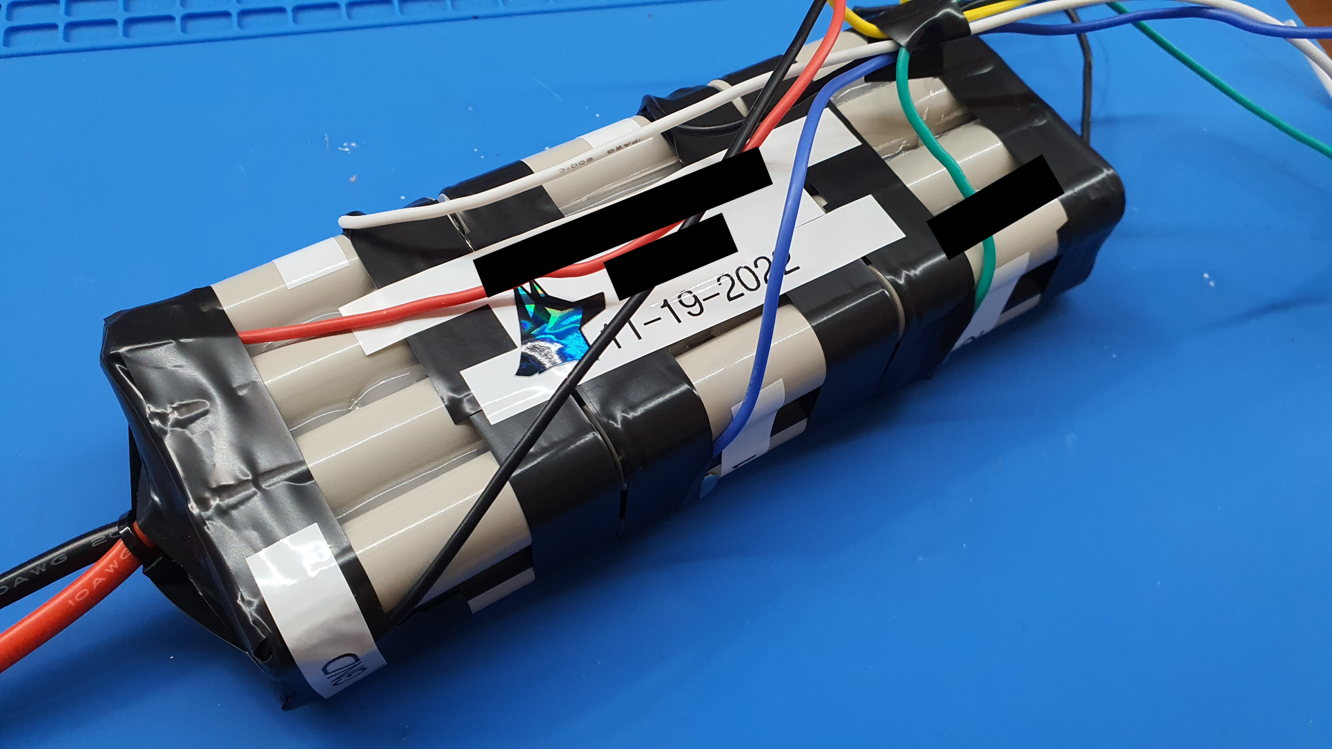
![]()
View of prototype battery pack build without the enclosure casing.
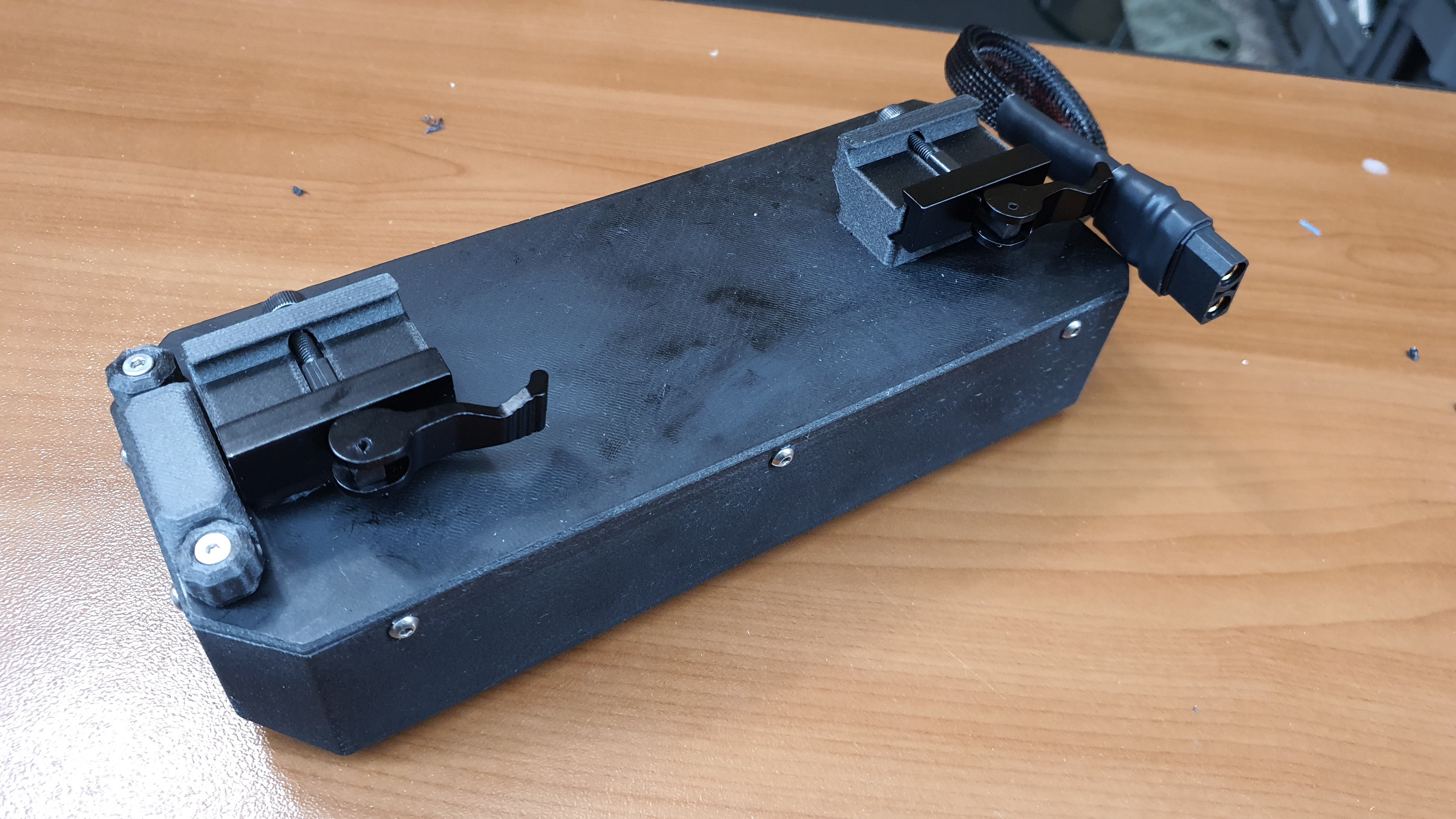
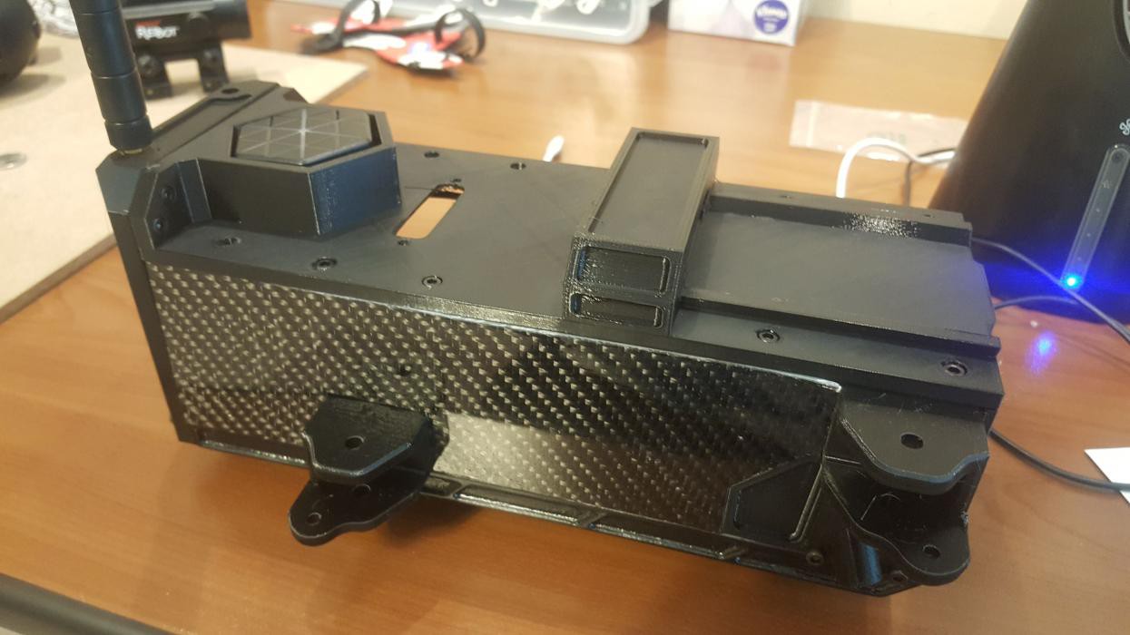
There are still two issues, the entire Unmanned Aerial System as a whole needs to be extremely durable for field use, including the battery. To save weight, Valor UAV uses skids on the bottom of the battery pack as landing gear. This means the battery pack has to be incredibly durable, so we designed an extremely durable casing enclosure. The enclosure is sealed and waterproof to keep the electronics dry. It features quick-release Picatinny clips at the top; an operator can clip in a new battery into a valor UAV in literally seconds. For anyone who's charged drone batteries, this is a big feature. The battery enclosure features an all-in-one single charge and discharges port separate from the flight discharge port. It's kept underneath a waterproof cap with two thumbscrews holding it in place.
![]()
The rugged outer casing; Notice the two front thumb screws enclosing the charge port, the Picatinny Quick-Release points, and the flight discharge cable.
Overall we're really happy with the flight battery! Because the battery is rail mounted and extremely modular, this leaves room to design specialty batteries in the future, including a Li-Po variant, larger cells, different chemistries, ones with features like integrated heaters for winter operations, etc. One person asked if Valor could be tethered with a ground power supply, and that can be very easily done! The possibilities are endless!
Hot-Start/Hot-Swap Switch System
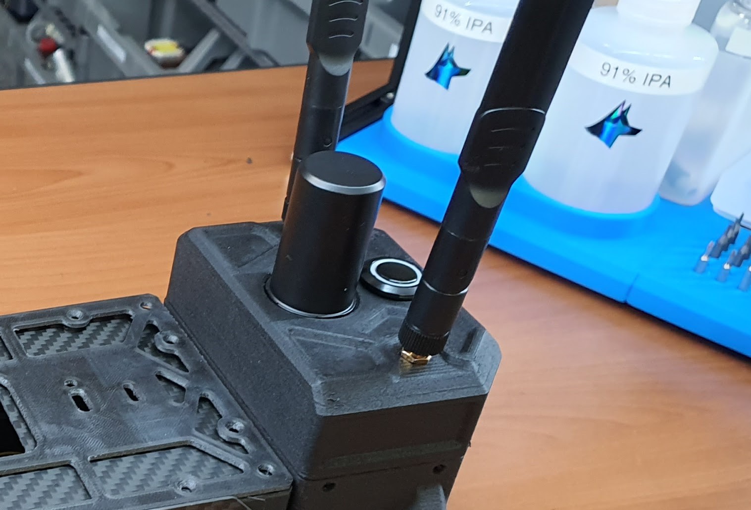
Commercial drones are often advertised for their rapid case-to-flight time. What they don't tell you is how slow GPS lock and radio connections for video systems could take. We aim to solve that with the Hot-Start/Hot-Swap switch system, its role is kind of like an APU on a jet. Valor has a small built-in battery that's separate from the flight battery. It's wired to only power the radio, avionics, and GPS. Before deploying the UAV to the mission location, Valor UAV can be powered on in advance, giving it time to gain GPS lock and RF C2/Video connections beforehand. Not only this but when Valor UAV needs a battery swap mid-mission, the Hot-Swap switch can be pressed to keep the necessary avionics on. No need to wait for the avionics to boot up again and regain connection, the vehicle is essentially kept "hot" until the fresh flight battery takes over. Another cool function is if Valor UAV is ever lost and the flight battery dies, the Hot-Start battery can kick in and keep the avionics alive for about an hour. This give operators a little extra time to recover the UAV.
![]()
View of the hot-start button between the 2 rear antennas
Wiring Harness & Custom Electronics
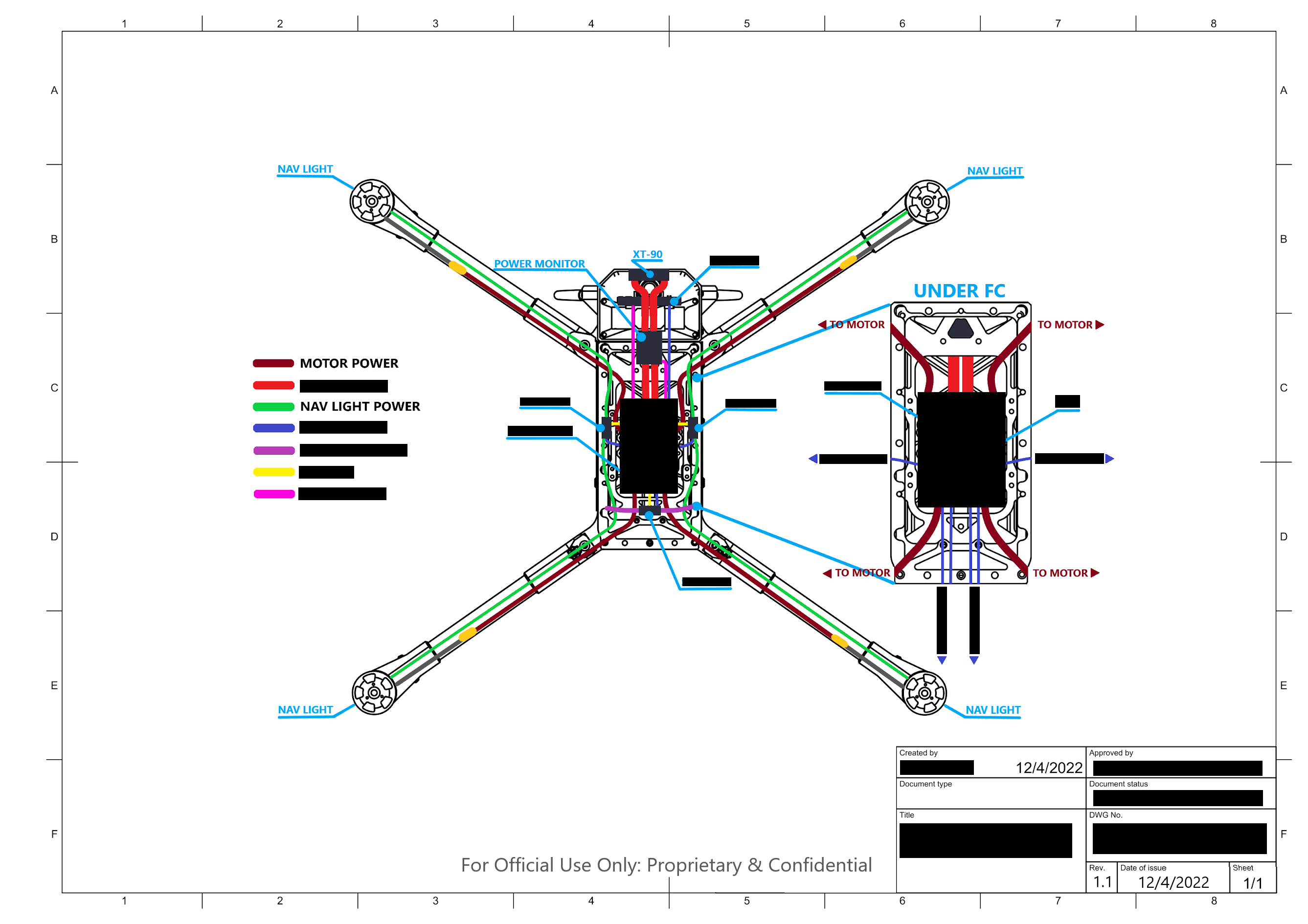
On your average scratch-build hobby drone, you can wire it in any manner you like following the basic flow. Valor UAV, however, is intended to maximize performance in every small measure possible, including using the shortest length of wiring possible and planning out the order strategically to maximize power efficiency. The benefits of such a drastic measure are debatable, but it's the attitude we would like to maintain to squeeze every bit of optimized performance out of our design. One critical outcome of detailed planning of the wiring harness so precisely was increased water resistance. Every extra bit of wire running between the arm and body is a point where water leakage could occur. By minimizing any potential for slack leaving gaps in the wire seal, or too high tensions also comprising the waterproof seal, we increased water resistance reliability.
![]()
Early revision of the wiring harness plan
![]()
Early dev photo, before custom carrier boards or wiring harness plan. A total mess and nightmare!
Valor was designed around open architecture and Commercial Off The Shelf (COTS) parts. There was no need to expend precious R&D time and money while simultaneously taking the risk of flying custom avionics. We took commercial drone parts and made a specific combination catered to Valor UAV. One thing for certain, half the drone components weren't meant to be used in a system like this, but thanks to open protocols and architectures, modifying and integrating was much simpler and much faster than if done from scratch.
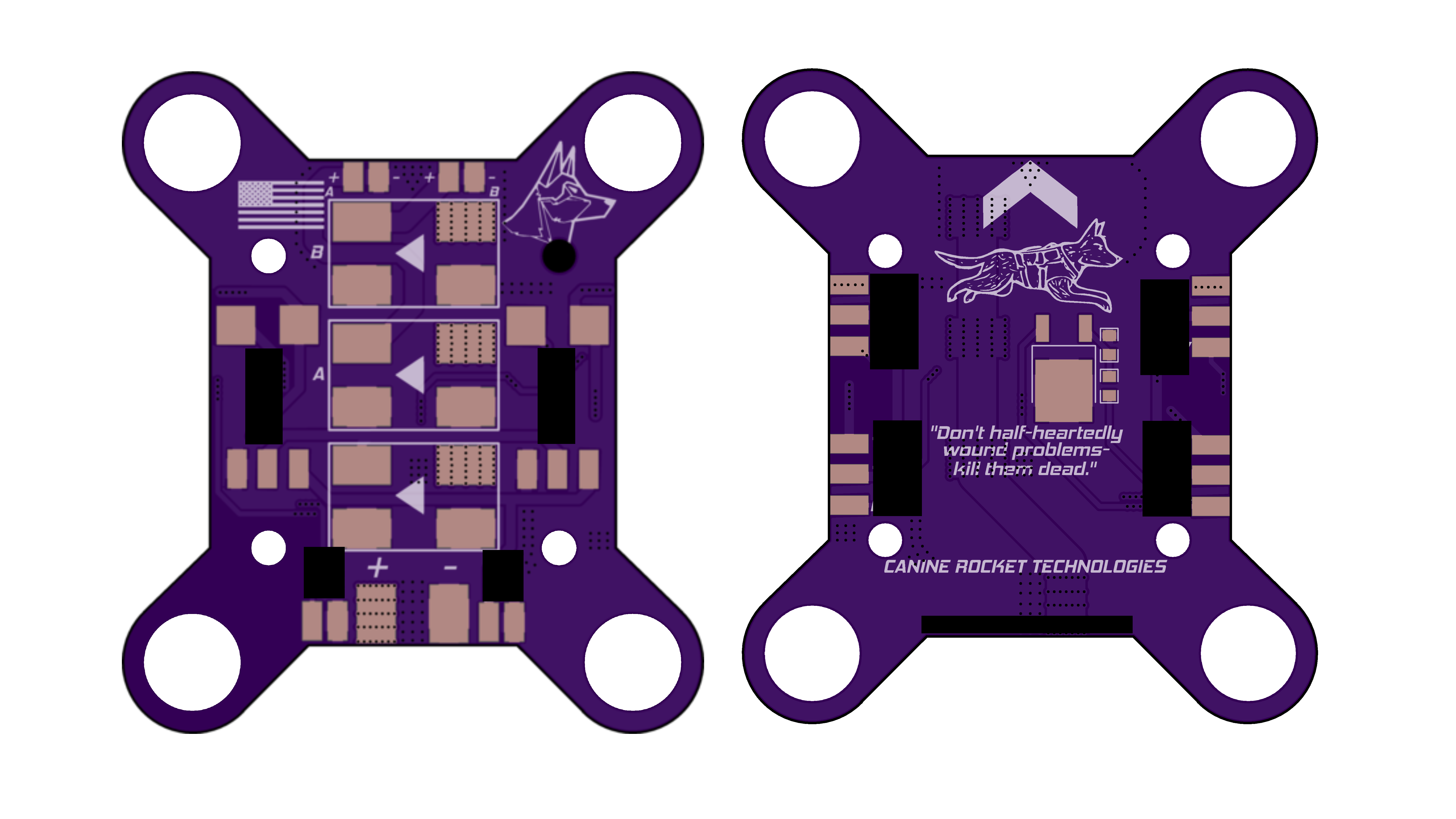
![]()
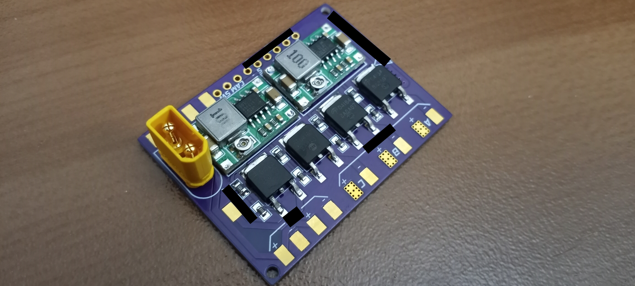
EDA render view of one of Valor's custom PCB Boards
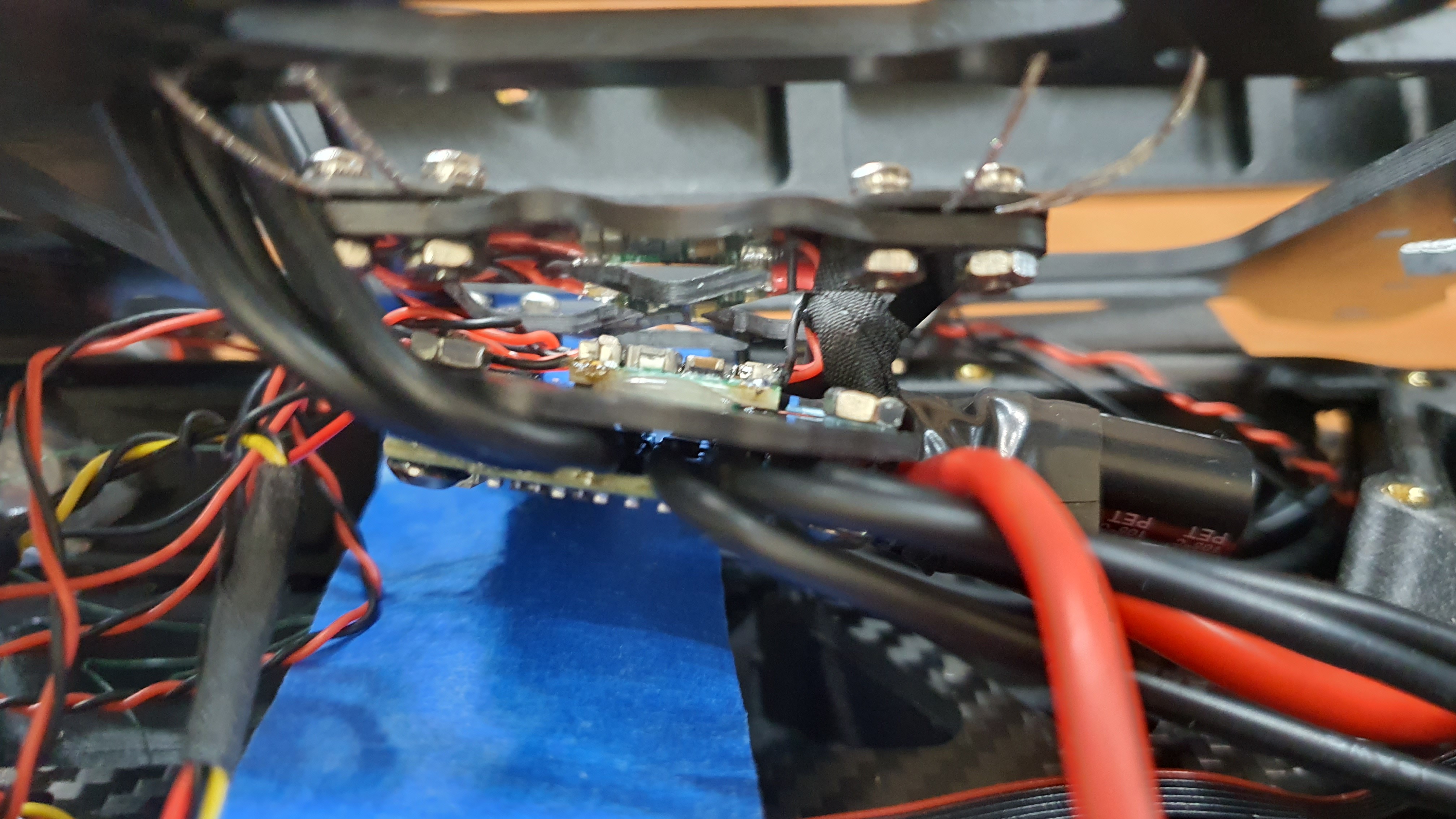
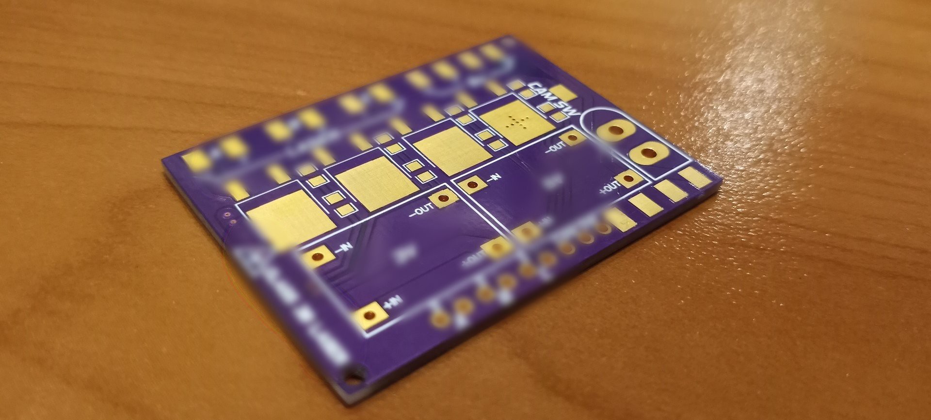
![]()
View of one of Valor's custom PCB board
![]()
Custom PCB board after assembly
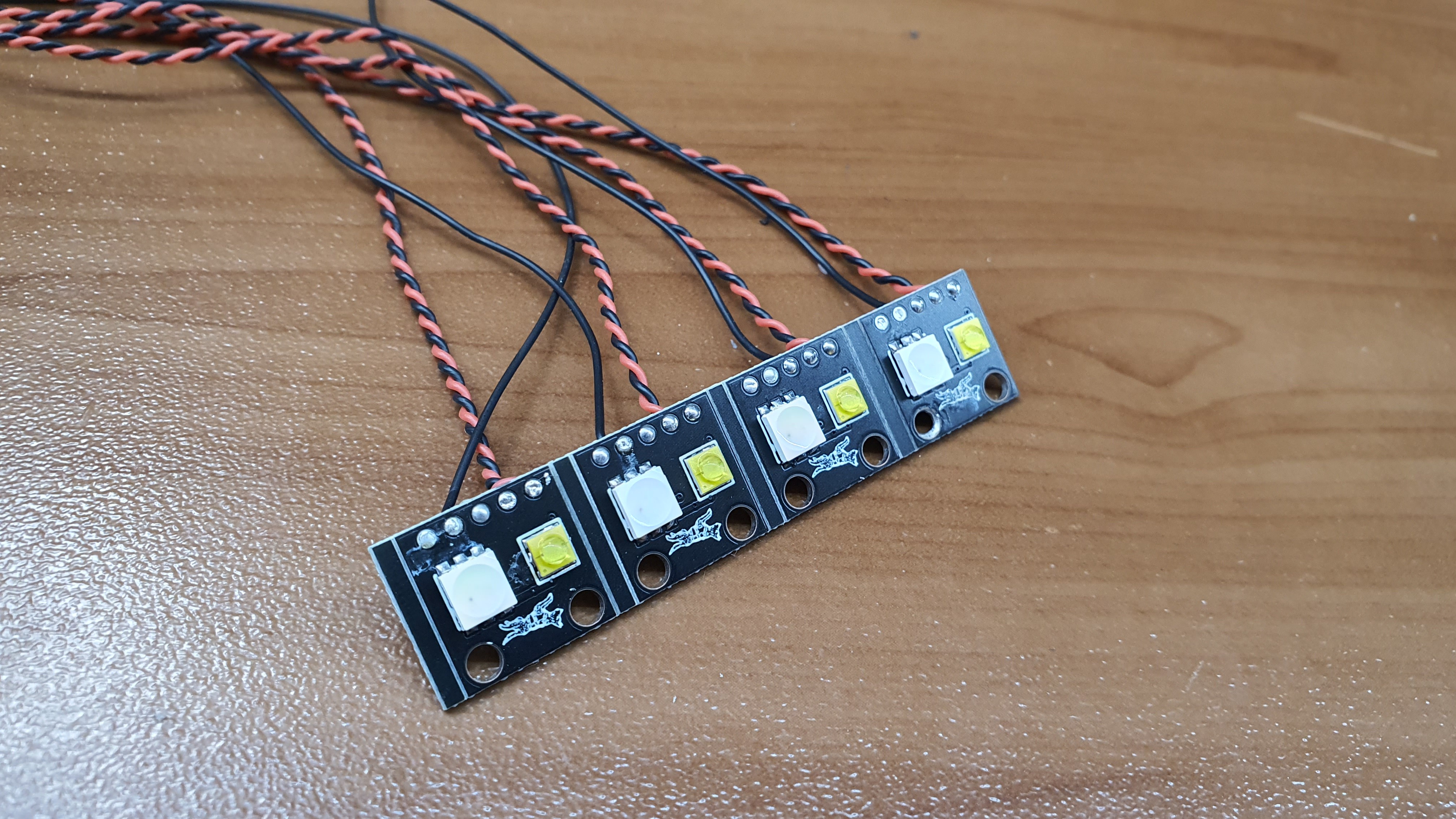
Despite its use of off-the-shelf drone parts, Valor UAV is not without its dose of internally developed custom boards. In the first article the custom navigation lights were featured, but custom electronics don't end there. There is a multitude of carrier board PCBs, intended to shed previous weight and make the wiring much cleaner. There are also handfuls of expansion slots and custom companion computers in the works to make the system smarter, but we can't discuss the details just yet!
-
UAV Hardware Assembly & Integration
12/15/2022 at 06:33 • 0 commentsUAV Assembly & Integration Summary
It's been a busy few months of in-house fabrication and chatting with some contractors who took care of machining and SLS 3D printing, but the parts are finally in the Lab and being integrated into the UAV assembly for assembly! Even during assembly, there were dozens of part design modifications and iterations pushed in CAD for a truly data-driven workflow. Below are some of the highlights of the now-integrated hardware!
![]()
View of the partially complete airframe during integration with dummy development optic pod placeholder
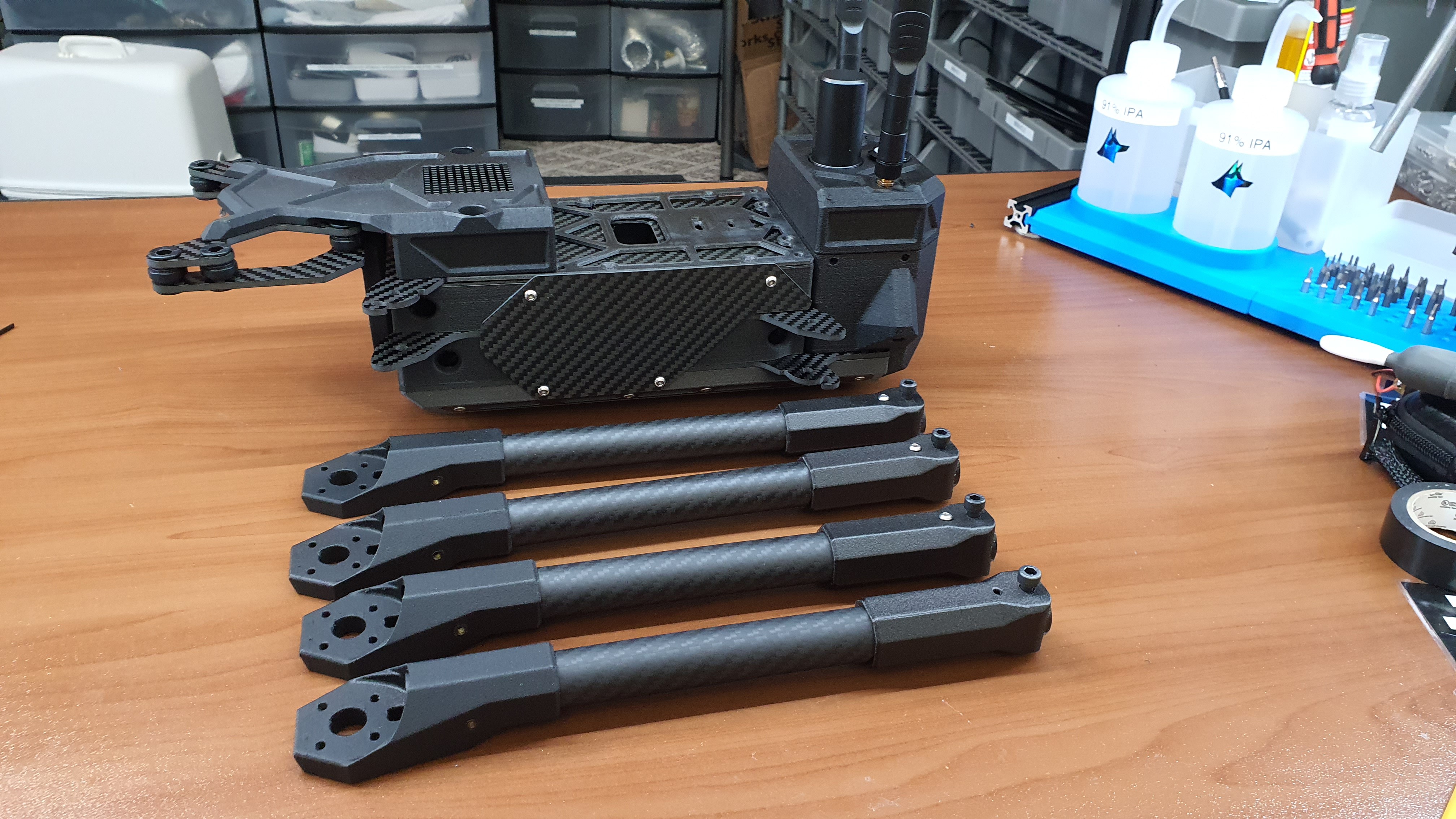
![]()
View of arms and airframe body before integration
![]()
Machined side payload rail
![]()
View of Central Carbon Fiber Structural Airframe
![]()
View of Universal Payload Interface Plate
![]()
View of custom Nav Light PCBs. Integrated RGB and super right white strobes!
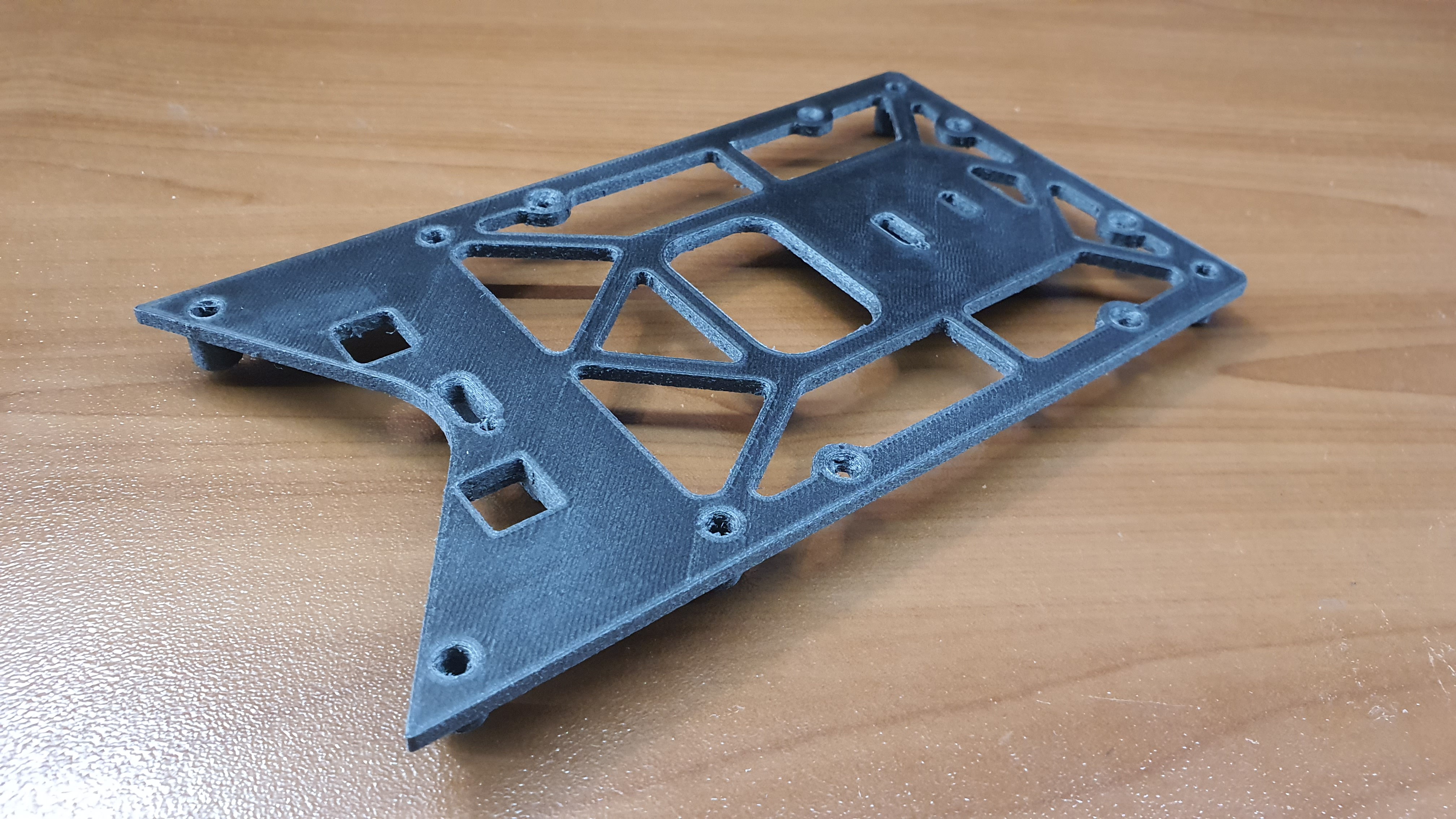
![]()
View of 3D printed airframe piece
![]()
Closeup view of arm assembly
Iterative Design, Material Selection, & Tight Mass Budget
One of the primary design challenges with Valor was balancing out durability, mass savings, and end-user easability. Often times decreasing the mass of the overall structure leads to comprises in durability. Every extra end-user easability feature is added mass that doesn't contribute to flight performance or flight time. All in all, the design requirements appear conflicting, but with careful consideration of material selection and design, the overall goal was achieved. There were simple measures such as switching all hardware fasteners from stainless steel to titanium. That measure alone shed off the weight of fasteners in the totality of 20%, an impressive figure. But this 20% mass shaving is a small save since the overall mass of fasteners is marginally small compared to the entire airframe, in comes the most challenging comprises.
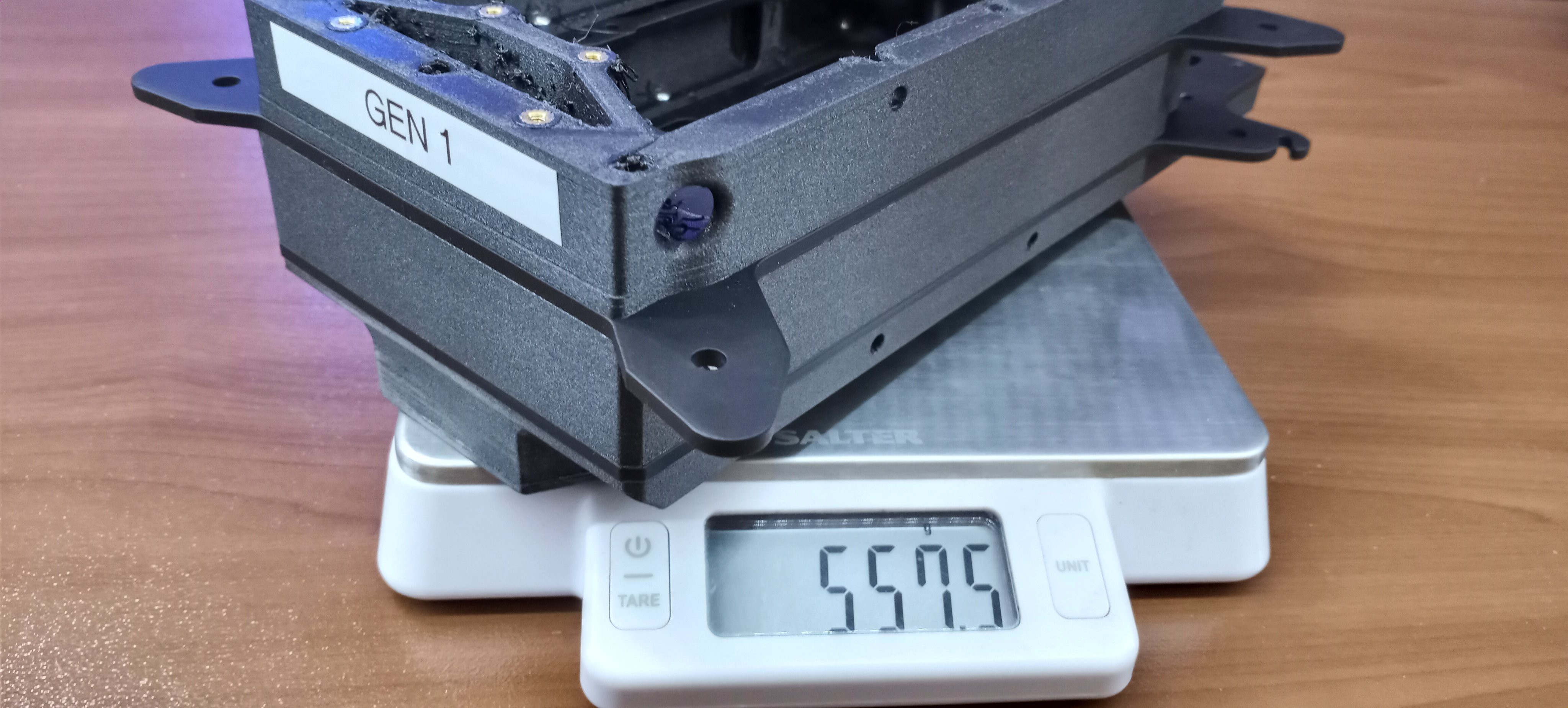
Initially to save weight we went with a "Exoskeleton" approach, a single 3D printed ariframe that would be skinned in carbon fiber. All the structural component were built into a single large body, including the SPOT optic pod. The critical flaw with this approach was the fact every component was permanently fixated together. In the case of a crash, a single component damage would require the entire airframe to be rebuilt. Not only that, modularity was severely comprised since essentially the entire UAV by and large was a single piece.
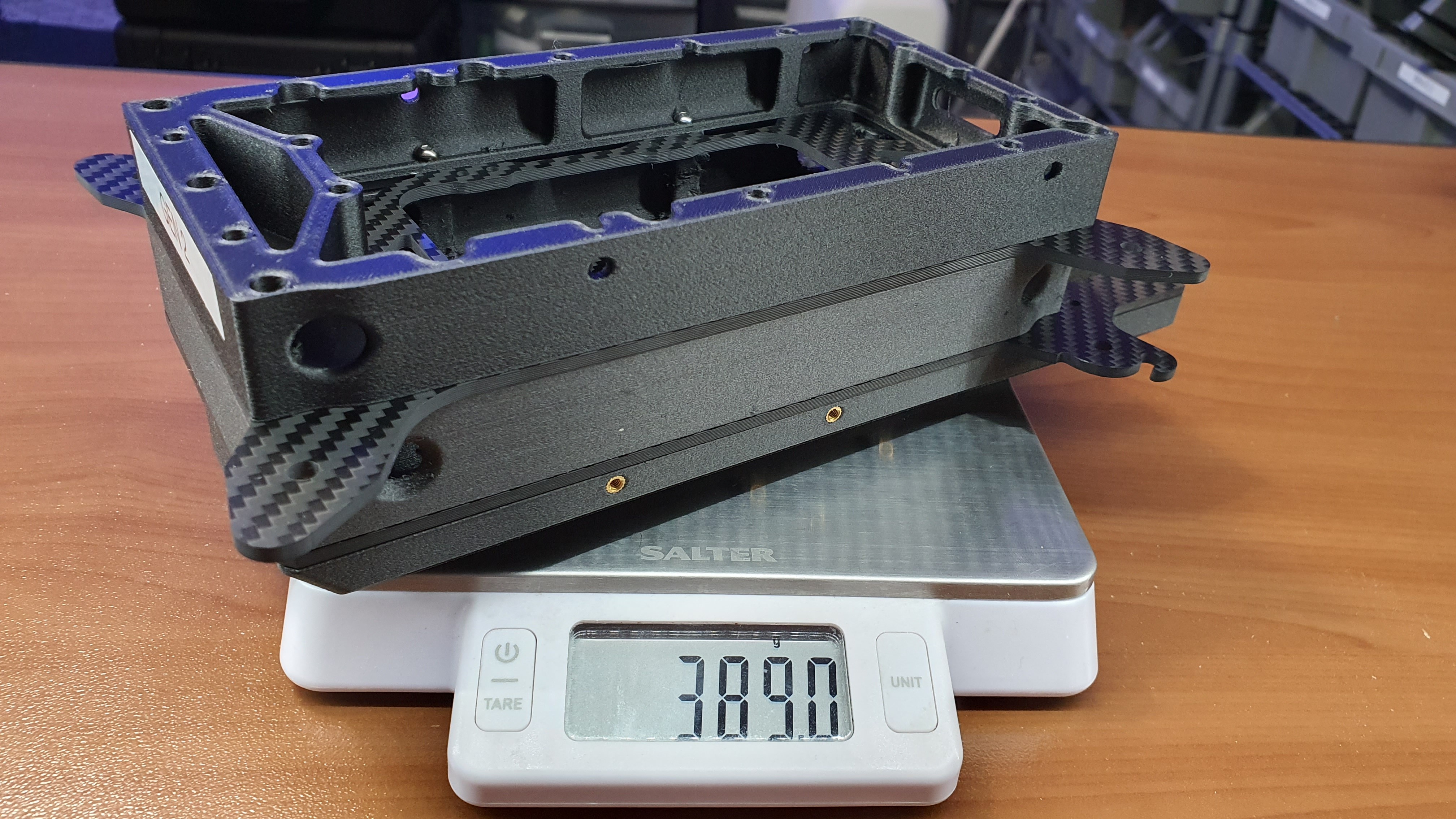
The V2 was much closer to what we settled with, multiple small modules that would assemble into each other. The problem with this approach was the strange angles gaps produced by the geometry of each module. This made effective waterproofing practically impossible (more or less highly impractical). The primary reason V2 was scrapped was the lack of stuctural integrity. Each arm joint was its own singular piece, and being FDM 3D printer, it was far too flexible to be an effective structural component.![]()
View of V1 airframe, a single piece design. In this version SPOT was going to be permanently mounted into the drone!
![]()
View of V2 airframe. Much closer to V3, but still had many limitations and shortcomings structurally.
Now the focus for V3 shifted to structural integrity. Modulairty, waterproofing, and weight are all important attributes, but essentially useless if the airframe can't take any loads in flight or in transport. In the design of V3 is alll came down to frame design and material selection. By making a stacked design, waterproofing was easy and naturally strcutual integrity was maximized. The clear winning material for strength and durability, one of the attributes of Valor sUAS we were aiming for, was alumnium. It checked off everything we were looking for except in mass. It was the singular source of bankrupting our mass budget. The switch to carbon fiber along with optimized print settings was the solution. We were shocked by how much weight we cut out with this simple change
![]()
View of extremely durable (But far too heavy) aluminum airframe dev prototype.
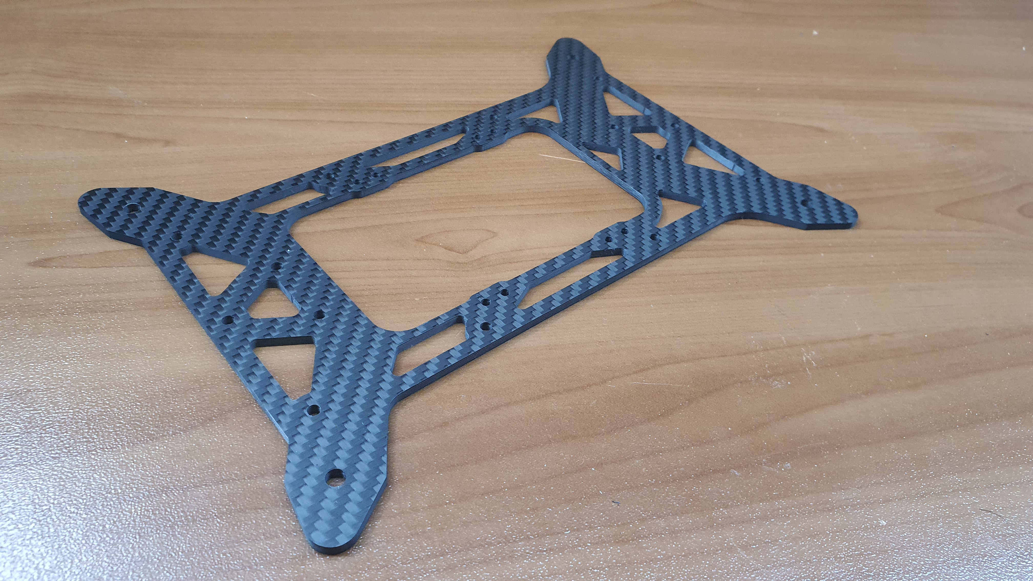
![]()
View of much lighter Carbon Fiber Airframe
![]()
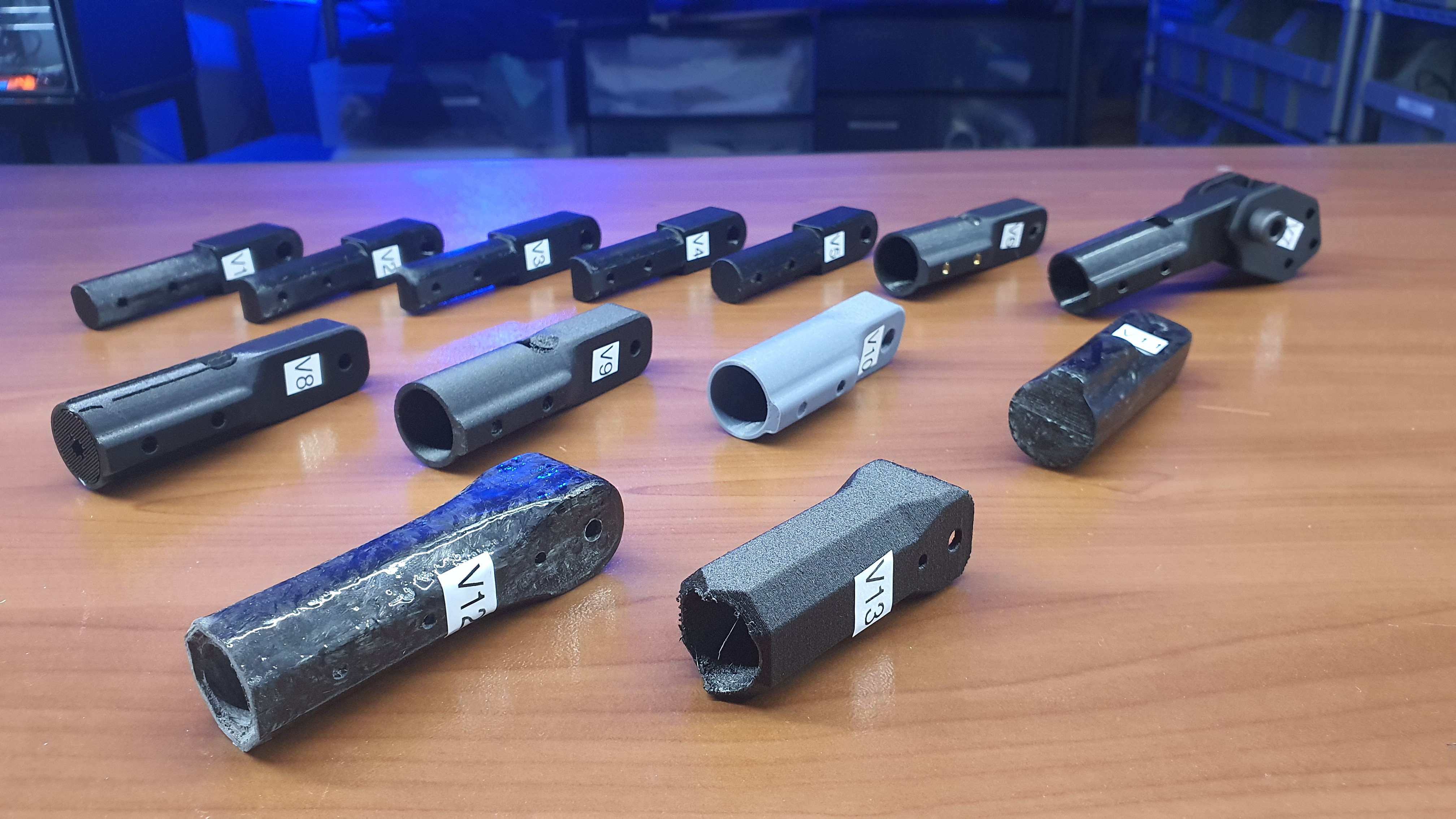
View of locking arm bracket iterations
The airframe was obviously a massive engineering challenge on its own, but no other part went through more iterations than the locking arm joints. The original arm joints were fully 3D printed, far too weak for the massive motors and props producing several kilograms of thrust and sending it straight into its joints, not to mention the multiplication of the load because of the moment the long motor arms create. The test phases for the arm joints were unintentionally very destructive and very stressful, the mid conclusion was that it would be impossible to achieve success without using stronger materials. We explored machining it out of metal to even SLM printing it out of metal, all very expensive solutions that would have led to the same bankruptcy of our mass budget. We were making the same mistake as we did with the airframe. The solution was much like the airframe, switch over to carbon fiber. But it would not be a typical layup but rather forged carbon fiber; use 3D printed molds and compression form a resin-chopped carbon fiber matrix. It worked really well, with one issue; the painstaking post-processing and matching required. It was simply not worth the effort.
At this point the realization came that the issue was not the material, it was the design of the bracket. The final flight version of the locking arm ended up being 3D printed after all, but it doesn't bear the brunt of the massive load as the previous versions did. With a very simple rudimentary design change, all the load is transferred into the already strong carbon tubes and airframe. All without a chunk of layer-by-layer molded plastic ready to snap at not even a quarter of the load it would experience in flight.
Valor Tactical Stealth sUAS
A low-cost multi-mission modular stealth UAV system