My #retrochallenge @retrochallenge 2021/10 entry - check out the logs for updates!
https://www.retrochallenge.org/p/entrants-list-202110.html
A follow-up on
https://hackaday.io/project/176466-microtronic-the-next-generation
and
https://hackaday.io/project/11560-the-talking-microtronic-computer-system-emulator
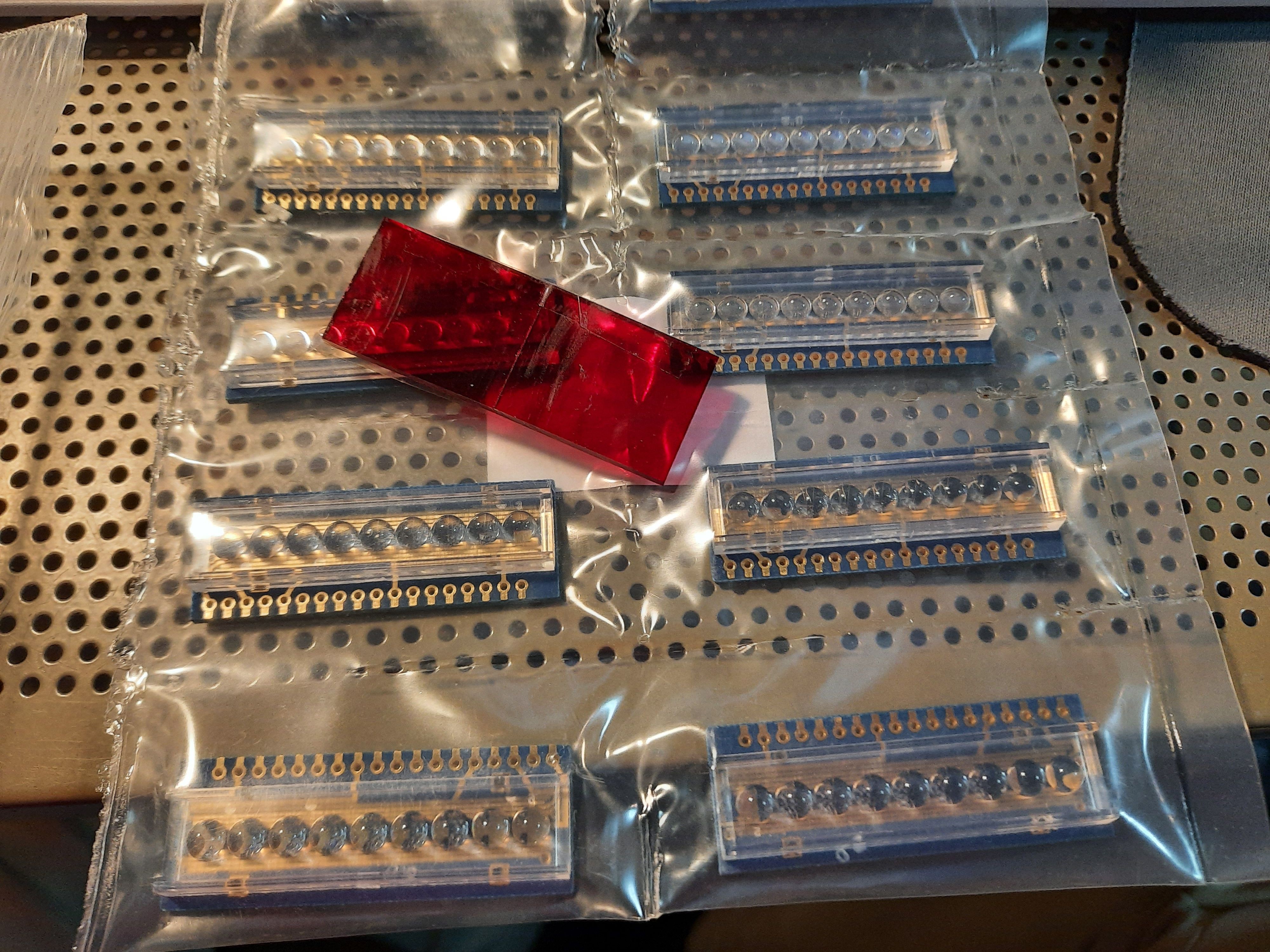
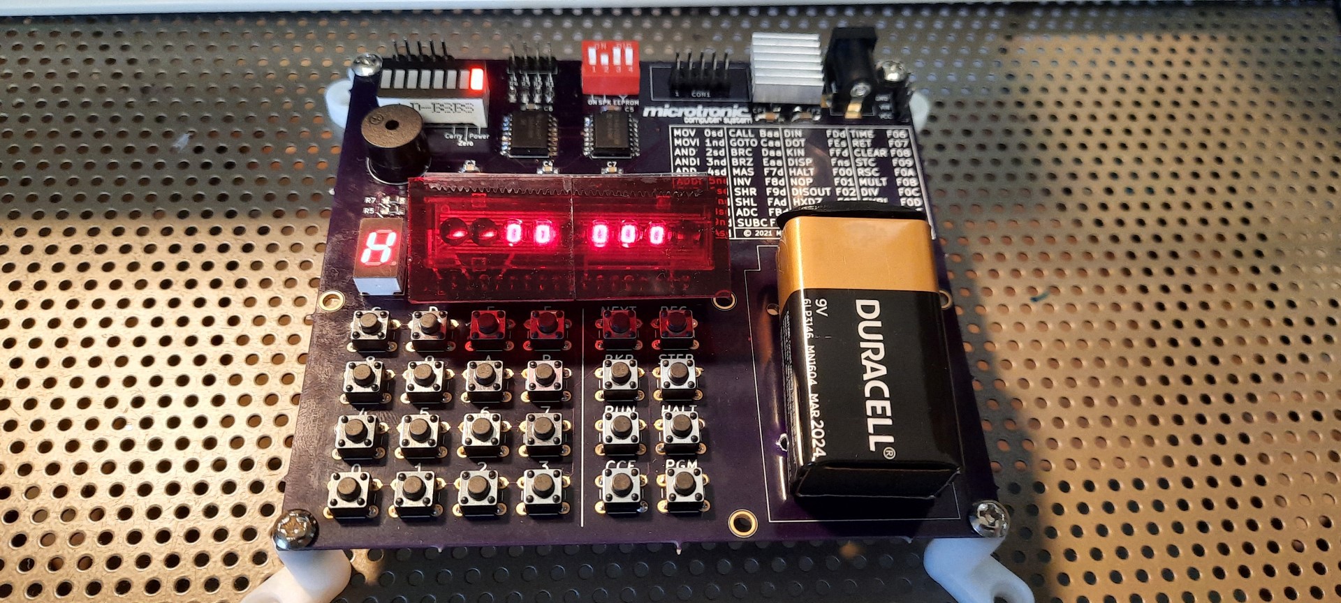
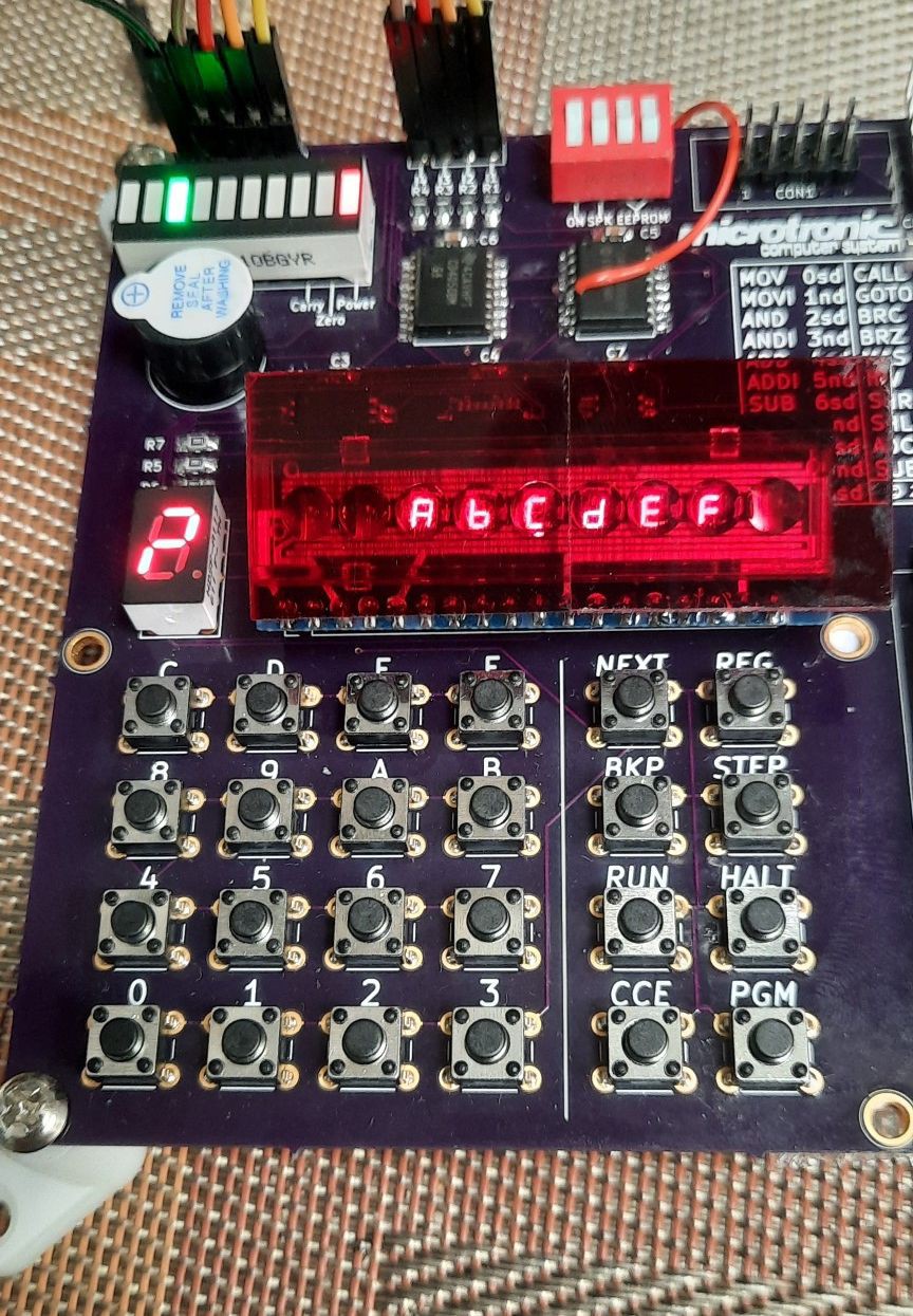
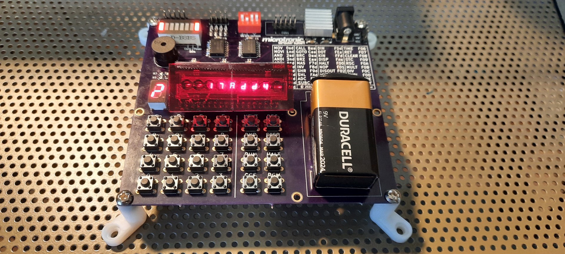
I found these adorable 6digit 7segment LED bubble displays which are very close to the ones used in the original Microtronic from 1981. I couldn't resist and had to make yet another version of my Microtronic emulator.
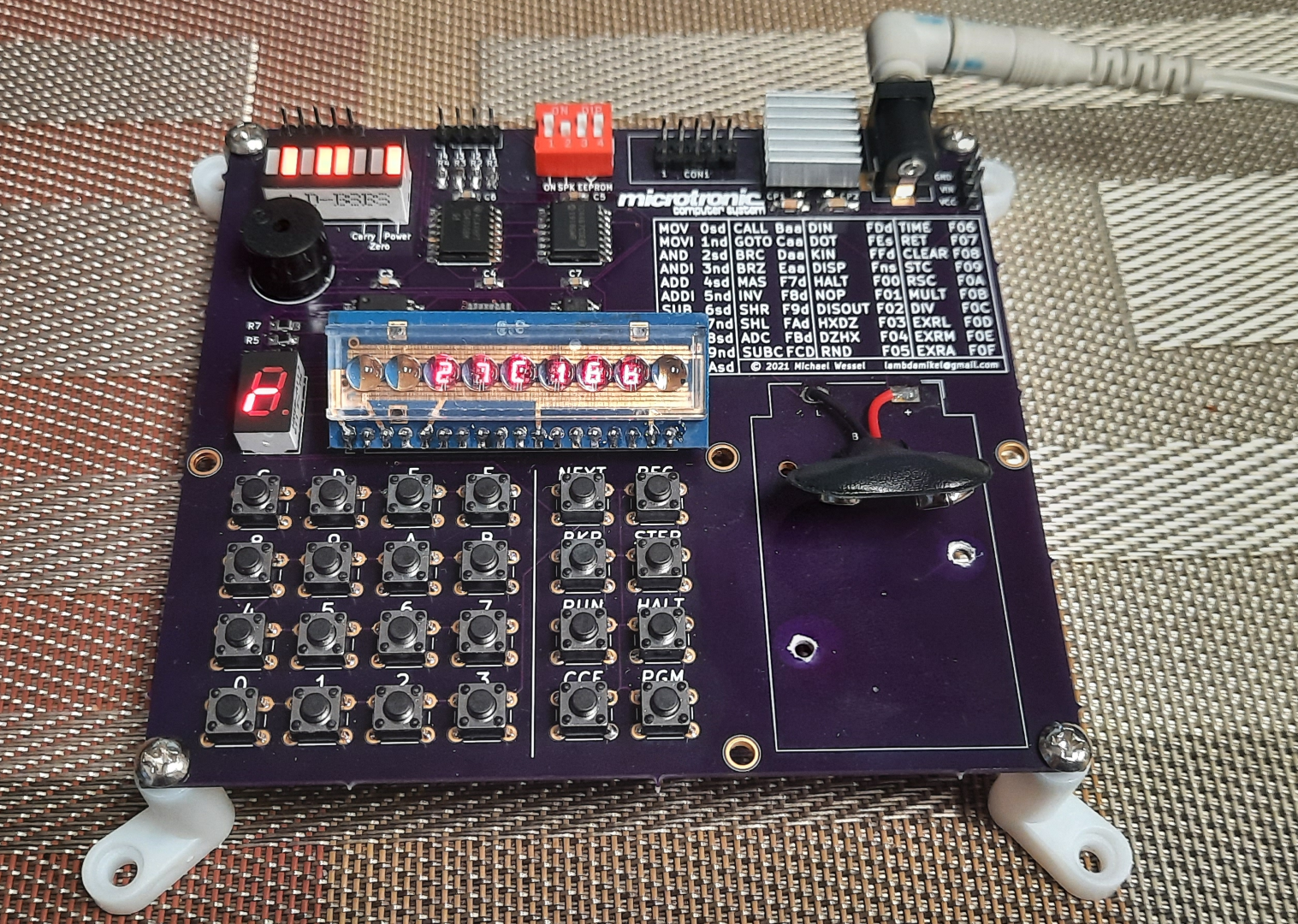
This time, the experience is 100% retro-authentic. The only difference over the original is that I have a blinking LED "cursor" in the display. Another goodie is the use of an EEPROM for program storage.
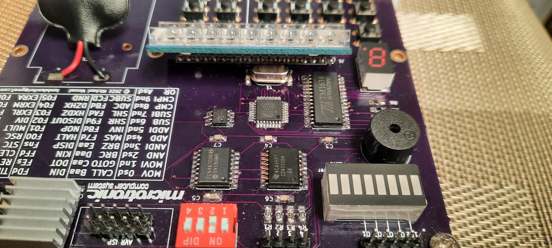
This is the first SMD PCB I ever made; I still need to improve my SMD soldering technique a bit, but it works!
Final RetroChallenge 2021 / 10 Update:
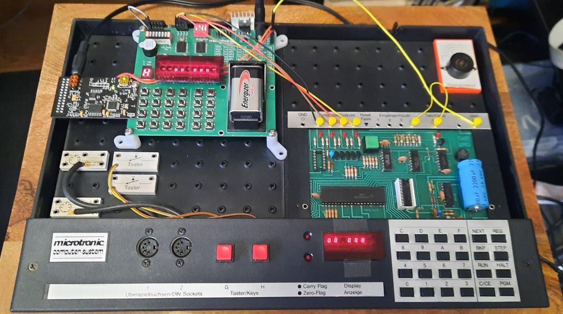
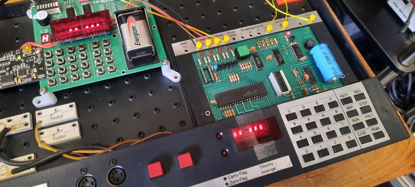
Let's wrap up my RetroChallenge 2021/10 contribution by demonstrating the original 1981 Microtronic, and how IT plays the drums, using the Microtronic emulator as its "drum module":
Previous updates:
Older Videos, not RetroChallenge related:
This demo features action games, and higher math:
Schematics:
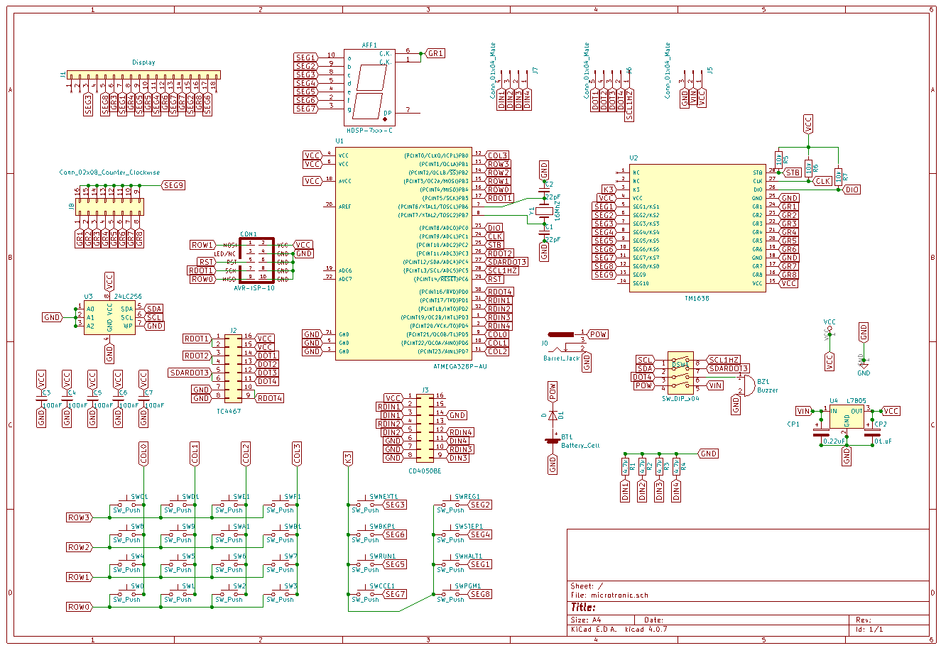
(There is also a PDF version of the schematics in the files section here).
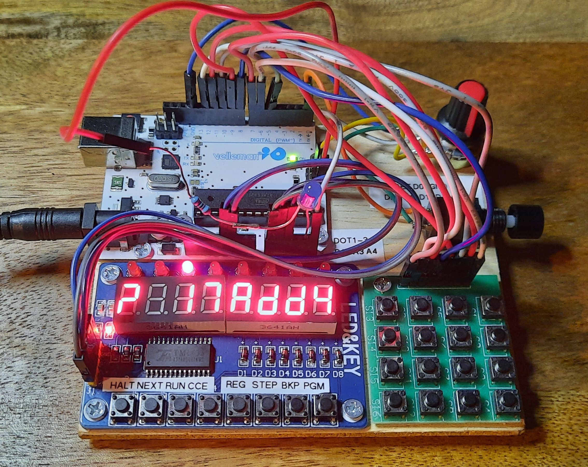
It started as an Arduino Uno R3 project in 2006:
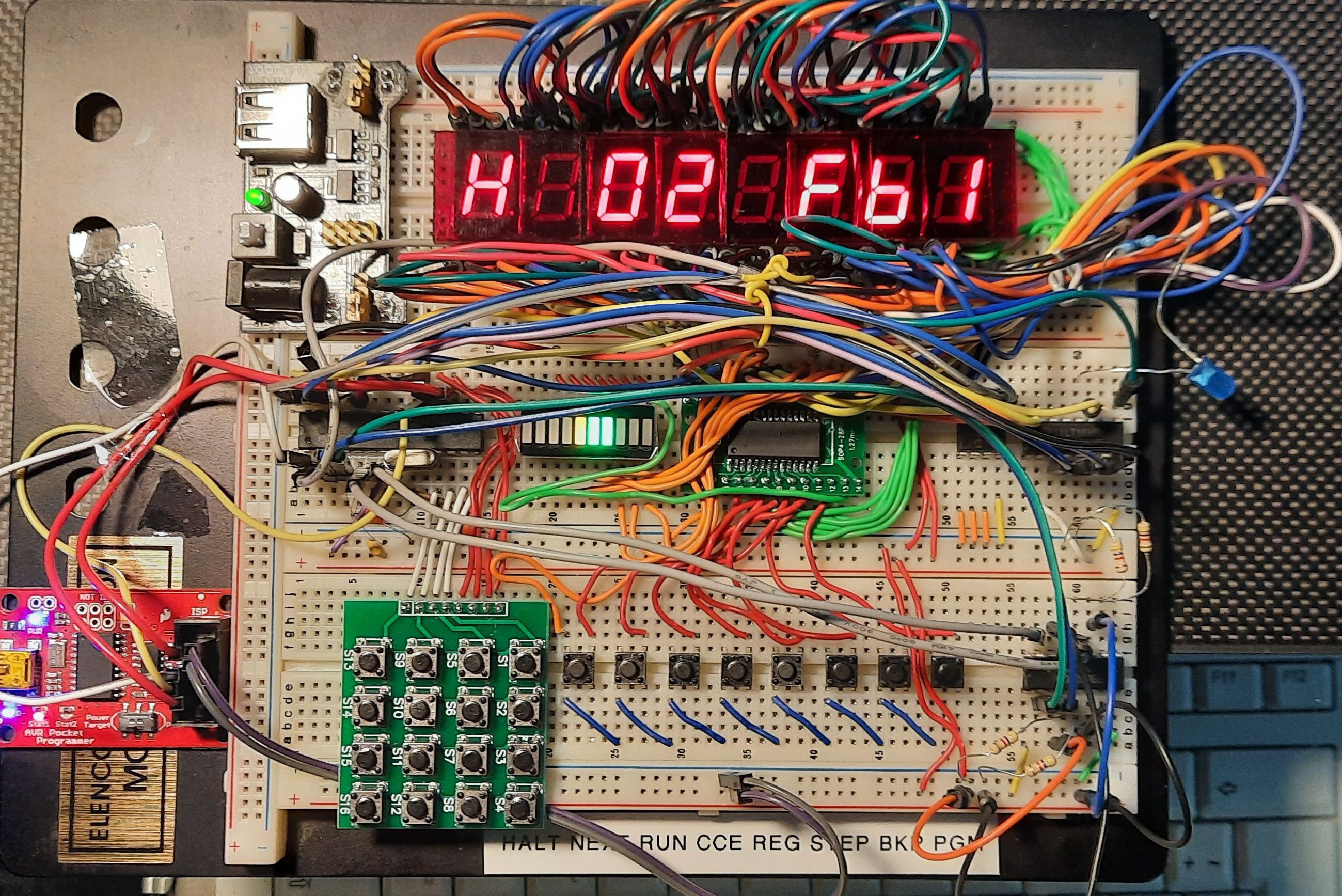
Then I re-engineered the "LED&KEY" module and acquired a number of TM1638 chips. Since they are only available as SMD, I had to bite the bullet and learn how to SMD solder. The result was a breadboard with one SMD chip (the TM1638) on a DIP carrier board:
Then I discovered the adorable 6segment LED bubble displays and realized that I could create an emulator with a very authentic look & feel:
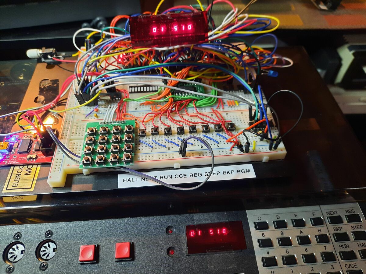
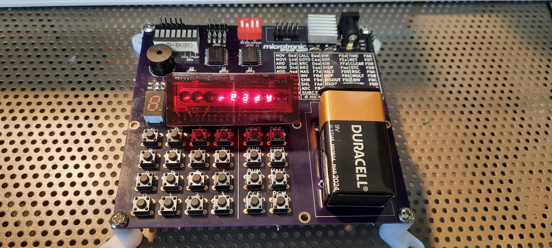
This evolved into the SMD PCB you are seeing:
 Michael Wessel
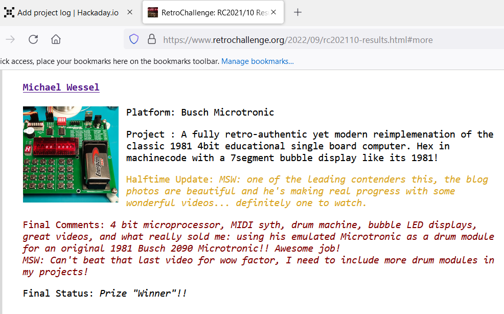


Congratulations on being a worthy winner. Nice job you did there. 👍