 Matthias Kampa
-
1Printing
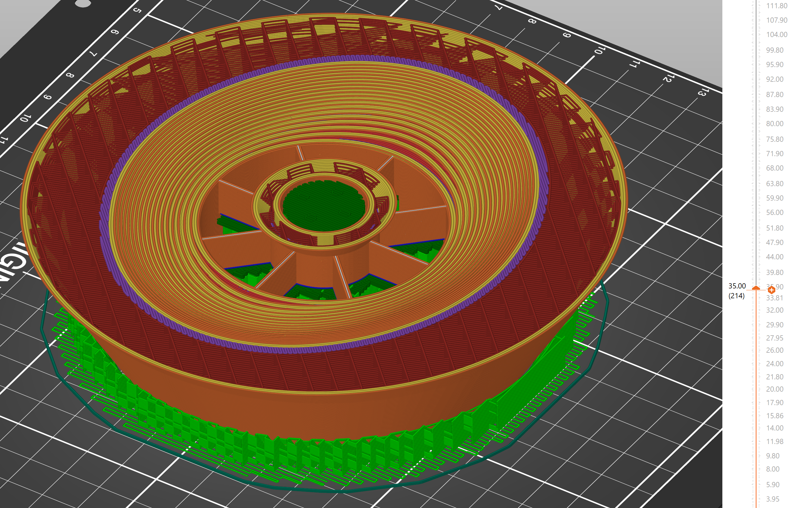
Print the STLs. The reflectors have to be white and the light trap black, but you can go wild on all the other parts. You can go fast (.2 to .3mm height, .6mm nozzle) on all the parts except the big reflector. Reduce the layer height to .15 to .2 for the latter. This is also the only part that requires some support material. "Supports on build plate only". Use a cylindrical modifiers to constrain the support to parts that wont be visible later. You can see the supports I used in green below (I sliced at .3 and it turned out a bit rough). Use 3-4 walls and your favorite infill. The big reflector should have rectilinar. Remove the bottom layers of the knob if you would like to expose the infill.
![]()
If you use different LEDs the reflector might not be compatible, but it's also not necessary. In that case you will also have to drill different holes for mounting them.
-
2Machining
Drill out the holes in the metal plates using a 10mm drill for the M8 screws to allow for some tolerance. Preferably with a drill-press, but not necessarily. You can take the measurements from the PDF stencil or print them out, but double-check your print settings and the paper because your printer might scale them. I almost fell for that one. The steel plate only needs the big holes and an additional hole for the power cable (place where you think it looks best).
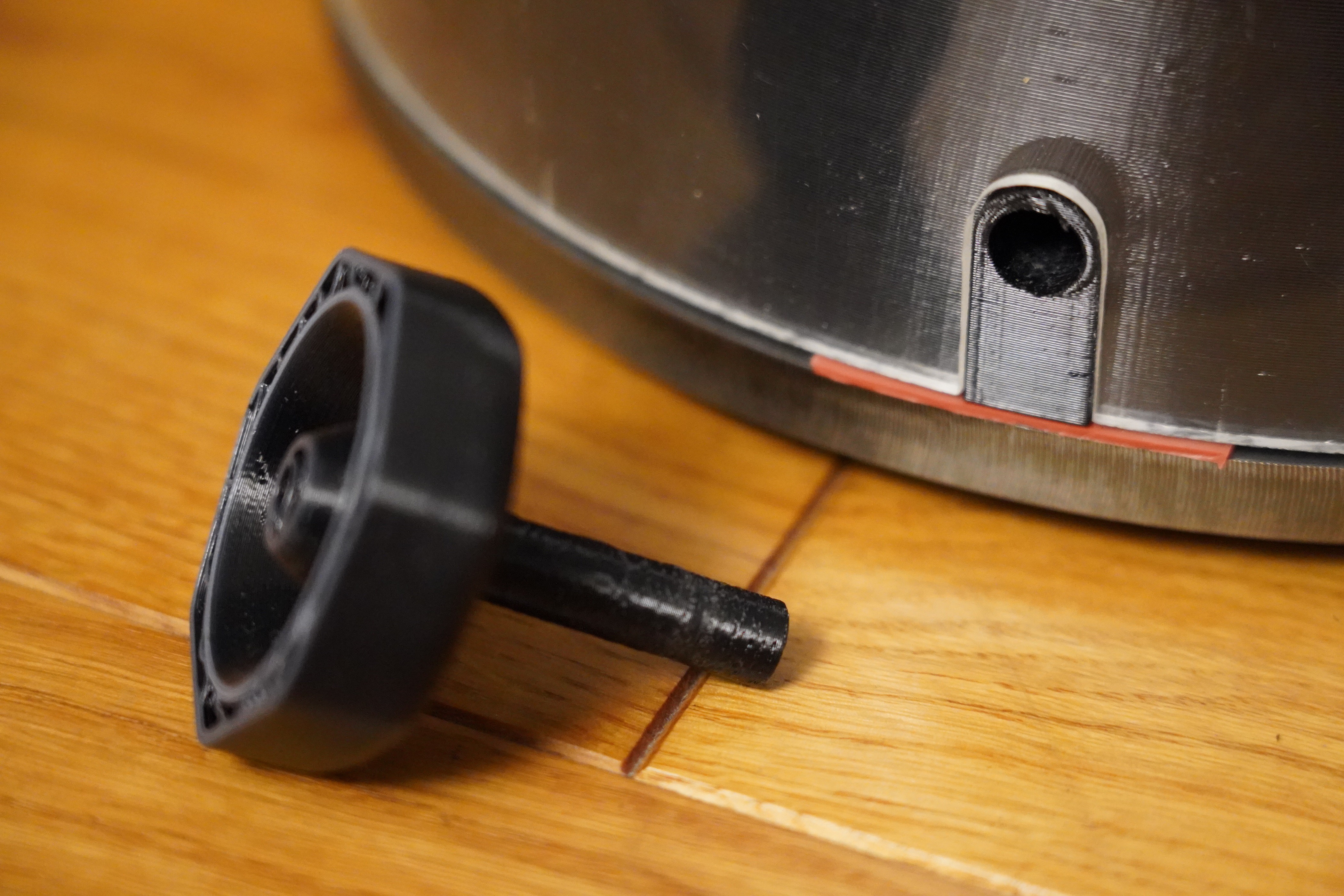
Use a saw and a fine round metal file to carve out the slit from the acrylic tube where the knob is. Use the print to make sure it fits. Rather too loose than too tight. The knob will cover it anyway. The PDF stencil can help you with the initial shape.
![]()
Cut out some roughly 3x2cm pieces from the silicone sheet. They will go between the big prints and metal plates. Let them stick out a bit. You can trim them to the outside of the metal plates with a knife. They are optional but do provide better dampening.
-
3Assembly
I wont describe any mains wiring. Use a safe power source and good practice. If you are not 100% certain you know what you are doing use external units to provide 12V for the motor and 5V for the LEDs. If you use an external source you will have to add a capacitor to reduce noise on the LED board. Anything >1000µF is sufficient.
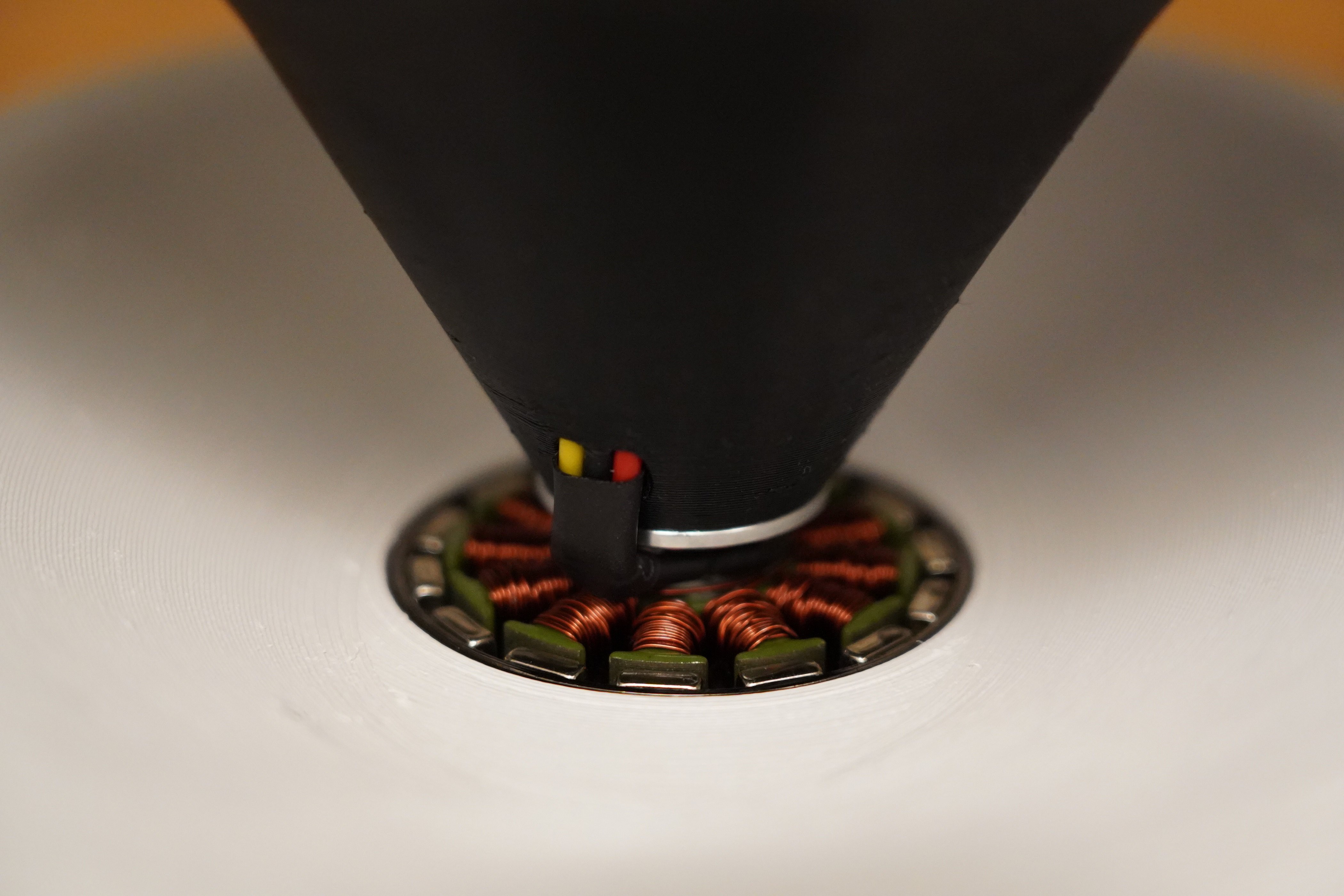
Pull the motor cables through the hole in the print and connect them to the driver board. Attach a power cable to the motor driver and pull it through the steel plate (or use an internal PSU according to the previous remark).
![]()
You can now assemble the reflector unit! Start by mounting the motor to the motor holder with 30mm M3 screws. Test the motor: The driver should be set to spin it counter-clockwise (looking at the rotating part of the motor). Use the screws that came with the motor to mount the driver board (or some other ~10mm M3 screws). Screw in the M8 bolts and don't forget to insert the silicone strips before tightening. Attach the big reflector using the 60mm M3 screws. Plop the ball bearing into the hole.
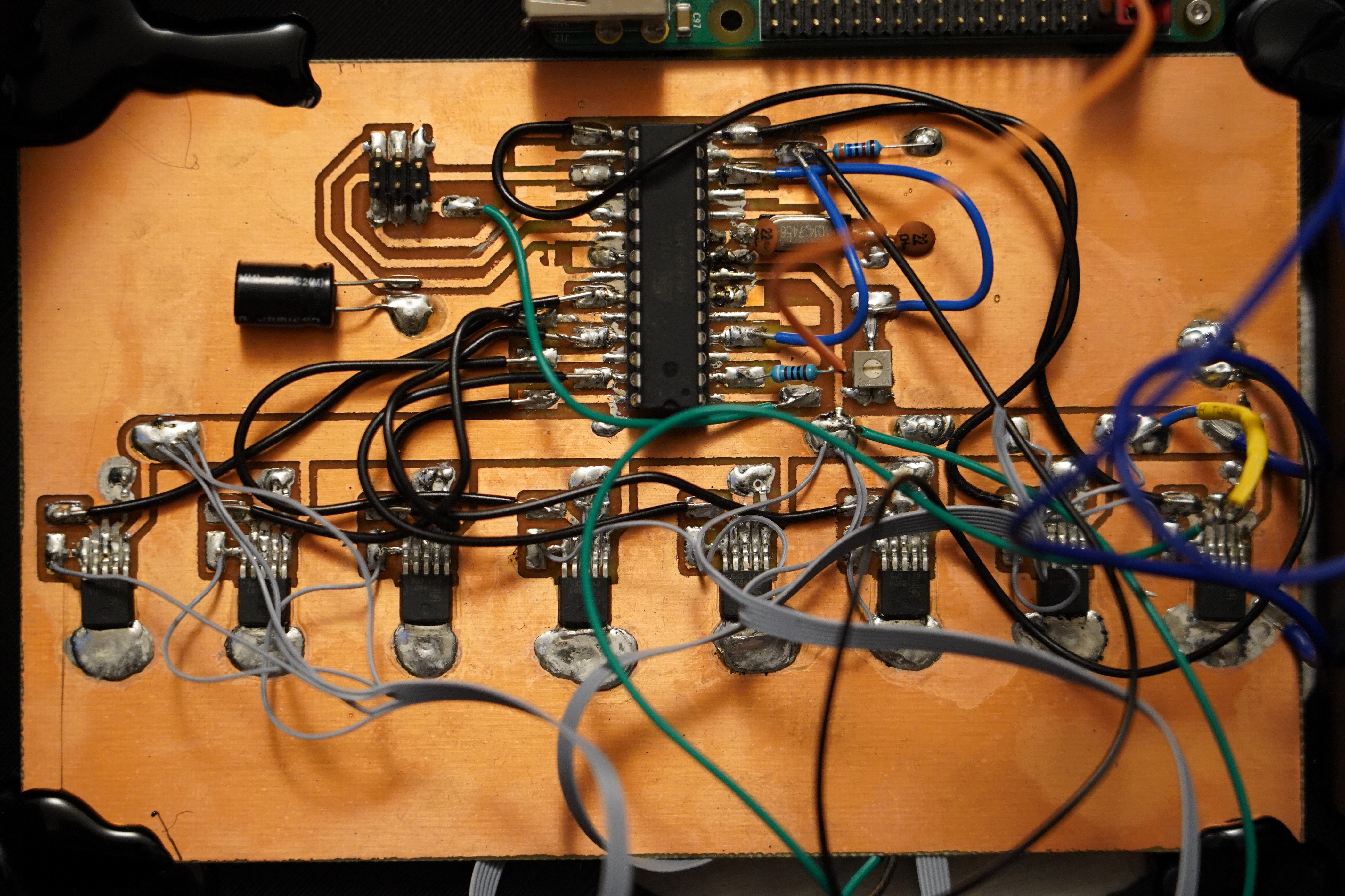
The PCB is made for easy etching and assembly. Yes, messy, but we urgently wanted to find out if the concept works. Use the picture and schematic if you don't know what goes where or ask if anything is unclear. Put the phototransistor in the bottom hole of the print that connects to the slit of the light barrier. Connect the IR LED and push it in the hole of the 3D print (flat backside). If it doesn't fit use a reamer, file or a drill to widen it. Use hot-glue if anything is loose. The crystal oscillator is optional. Change the frequency in the code if you don't use a crystal or a different frequency than 14745600Hz.
![]()
Solder wires to the LED boards and pull the wires through the metal plate. You can pay attention to which color goes where, but I just randomly connected them to the drivers and changed the pins in software later. Pull the LED and light barrier wires through the holes in the aluminum plate. Mount the LEDs using the reflector. Thermal paste recommended but optional. Mount the light trap and bottom cover using M8 bolts. (And don't forget some more silicone pieces.)
Mount the raspberry pi with screws and the board with hot glue. Solder the LED wires to the pads next to the drivers. The photoresistor needs to be connected to 5V with the long pin. Short one goes to the pad next to the mega where you also see its pull-down to ground. Connect RX to the raspberry's TX. Connect any part of the ground plane and the thick 5V rail to the power source and connect the raspberry to it as well.
Flash code via Atmel studio and an ISP programmer. I provided a HEX file, but recommend using the ASM so you can flip the pins of the LEDs or alter it for your set of colors.
Run the python code on the raspberry or let it run automatically on boot.
Use the knob to start the motor. Only go as fast as you need to for a flicker-free display. I went all the way and didn't break anything, but don't risk it. It's obviously a prototype device, so no guarantees. Adjust the potentiometer to set the trigger level for the light barrier.
The device also works upside-down, but you will have to change the direction of rotation or the python code.
That should be it. Enjoy! And please send me a picture. - Especially if you added a yellow LED.
HoloLamp - Between display concept & physics class
A clock that encodes two dimensions into a multispectral PoV stripe - put on diffraction filter glasses to decode it
Discussions
Become a Hackaday.io Member
Create an account to leave a comment. Already have an account? Log In.