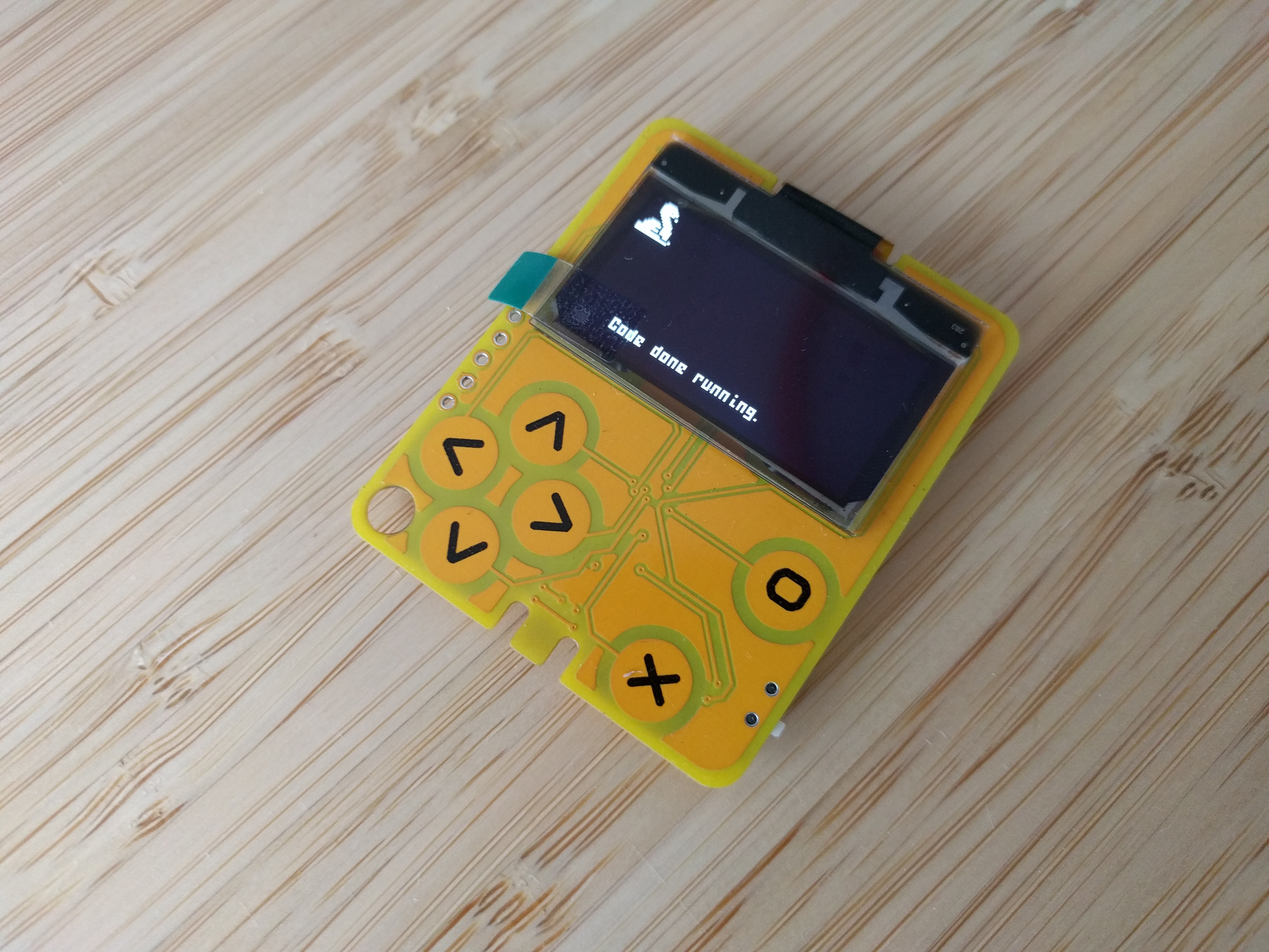
Last time we got the CircuitPython firmware running on the device, but the display initialization code was all in Python. Today we are going to move it all into the firmware, so the device starts with the display initialized.
We will be putting our initialization code into the board.c file, and it looks like this:
#include "supervisor/board.h"

#include "shared-bindings/board/__init__.h"
#include "shared-bindings/displayio/FourWire.h"
#include "shared-module/displayio/__init__.h"
#include "shared-module/displayio/mipi_constants.h"
#include "shared-bindings/busio/SPI.h"

displayio_fourwire_obj_t board_display_obj;

#define DELAY 0x80

uint8_t display_init_sequence[] = {
    0xae, 0, // sleep
    0xd5, 1, 0x80, // fOsc divide by 2
    0xa8, 1, 0x3f, // multiplex 64
    0xd3, 1, 0x00, // offset 0
    0x40, 1, 0x00, // start line 0
    0xad, 1, 0x8b, // dc/dc on
    0xa0, 0, // segment remap = 0
    0xc0, 0, // scan incr
    0xda, 1, 0x12, // com pins
    0x81, 1, 0xff, // contrast 255
    0xd9, 1, 0x1f, // pre/dis-charge 2DCLKs/2CLKs
    0xdb, 1, 0x20, // VCOM deslect 0.770
    0x20, 1, 0x20,
    0x33, 0, // VPP 9V
    0xa6, 0, // not inverted
    0xa4, 0, // normal
    0xaf, 0, // on
};

void board_init(void) {
    busio_spi_obj_t *spi = &displays[0].fourwire_bus.inline_bus;
    common_hal_busio_spi_construct(spi, &pin_PA09, &pin_PA08, NULL);
    common_hal_busio_spi_never_reset(spi);

    displayio_fourwire_obj_t *bus = &displays[0].fourwire_bus;
    bus->base.type = &displayio_fourwire_type;
    common_hal_displayio_fourwire_construct(bus,
        spi,
        &pin_PA10, // Command or data
        &pin_PA01, // Chip select
        &pin_PA00, // Reset
        1000000, // Baudrate
        0, // Polarity
        0); // Phase

    displayio_display_obj_t *display = &displays[0].display;
    display->base.type = &displayio_display_type;
    common_hal_displayio_display_construct(display,
        bus,
        128, // Width
        64, // Height
        2, // column start
        0, // row start
        0, // rotation
        1, // Color depth
        true, // grayscale
        false, // pixels in byte share row. Only used with depth < 8
        1, // bytes per cell. Only valid for depths < 8
        false, // reverse_pixels_in_byte. Only valid for depths < 8
        true, // reverse_pixels_in_word
        0, // Set column command
        0, // Set row command
        0, // Write memory command
        0xd3, // set vertical scroll command
        display_init_sequence,
        sizeof(display_init_sequence),
        NULL,
        0x81,
        1.0f, // brightness
        false, // auto_brightness
        true, // single_byte_bounds
        true, // data as commands
        true, // auto_refresh
        60, // native_frames_per_second
        true, // backlight_on_high
        true); // SH1107_addressing
}

bool board_requests_safe_mode(void) {
    return false;
}

void reset_board(void) {
}
This is basically copied from pygamer's board.c, with the initialization sequence and the display arguments copied from the SH1106 driver code. There are, however, three changes I made.
First of all, of course I had to change which pins are being used — this is pretty straightforward.
Then, I had to rotate my display up-side-down. I could have done this with the "rotation" argument of the display, but I want to write some code that writes to the display directly, so I really wanted to rotate it in its initialization. This is what the "segment remap" and "scan direction" registers are for, and I changed them both to 0.
Finally, the way the displays I got are constructed, the first two columns are not connected, so I set "column start" to 2, to compensate for that.
After compiling and flashing this, and removing the Python code from the last time, I get a working display. I also tested that it works powered from a CR2032 battery.

 deʃhipu
Discussions
Become a Hackaday.io Member
Create an account to leave a comment. Already have an account? Log In.