-
The future
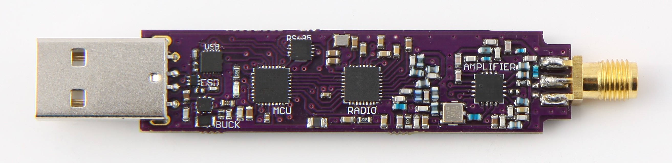
01/27/2017 at 06:40 • 1 commentThe fourth version is alive. Hopefully it will be dummy-proof enough to be programmed without headaches or the need for expensive diagnostic equipment. The following features are being evaluated in this iteration.
- Through-hole USB connector – Previous surface mount seemed pretty fragile. Through-hole attachment should be more resilient.
- Temperature compensated oscillator – Use of TXCO with +-2ppm stability instead of the +-10ppm crystal oscillator.
- RS485 – Development of new interface based on feedback. With it, the device can be used as wireless extension of RS485 bus further improving integration into sensor network.
![]()
Version 4 has undergone crowdfunding campaign at CrowdSupply. Unsuccessfully. You can check its old page. Device may be eventually found on Tindie. This day has yet to come.
Wondering why to use sub-GHz radio instead of wifi? Main reason is range. Sub-GHz radio trades speed for range, which means you can easily have triple range of wifi, but with only few kilo bits per second. As mentioned in other logs this device is tested to reach 500meters at 4,8kbps with wire antenna 8cm long. Range can be further improved by lowering bitrate or improving antenna.
Let’s take a look on few example applications you could use this device for :
- Wireless COM port – Pair two devices together and use them as point-to-point datalink allowing you slow, but long range link to remote devices. ( Like solar powered Raspberry Pi inside your greenhouse? )
- Radio-to-RS485 bridge – Because maybe your greenhouse have sensor network of its own. Can also be used to replace long coax wires going from rooftop antennas to your radio. You can put this device in a box right by the antenna and route it’s data on RS485 bus avoiding radio signal losses.
- Instant messaging broadcast – Simple chat. Useful in places with poor internet connection or as back-up communication.
- Platform for proprietary protocol or encryption – Define custom protocol or embed encryption into the lowest level of transmission. This reduces chances of your algorithm being cracked.
- Spectrum analyzer – Device can be configured to give feedback about strength of received signal. This can be send to attached computer which could visualize the data. You can use this to form poor man’s radio spectrum analyzer or to estimate distance of the transmitter.
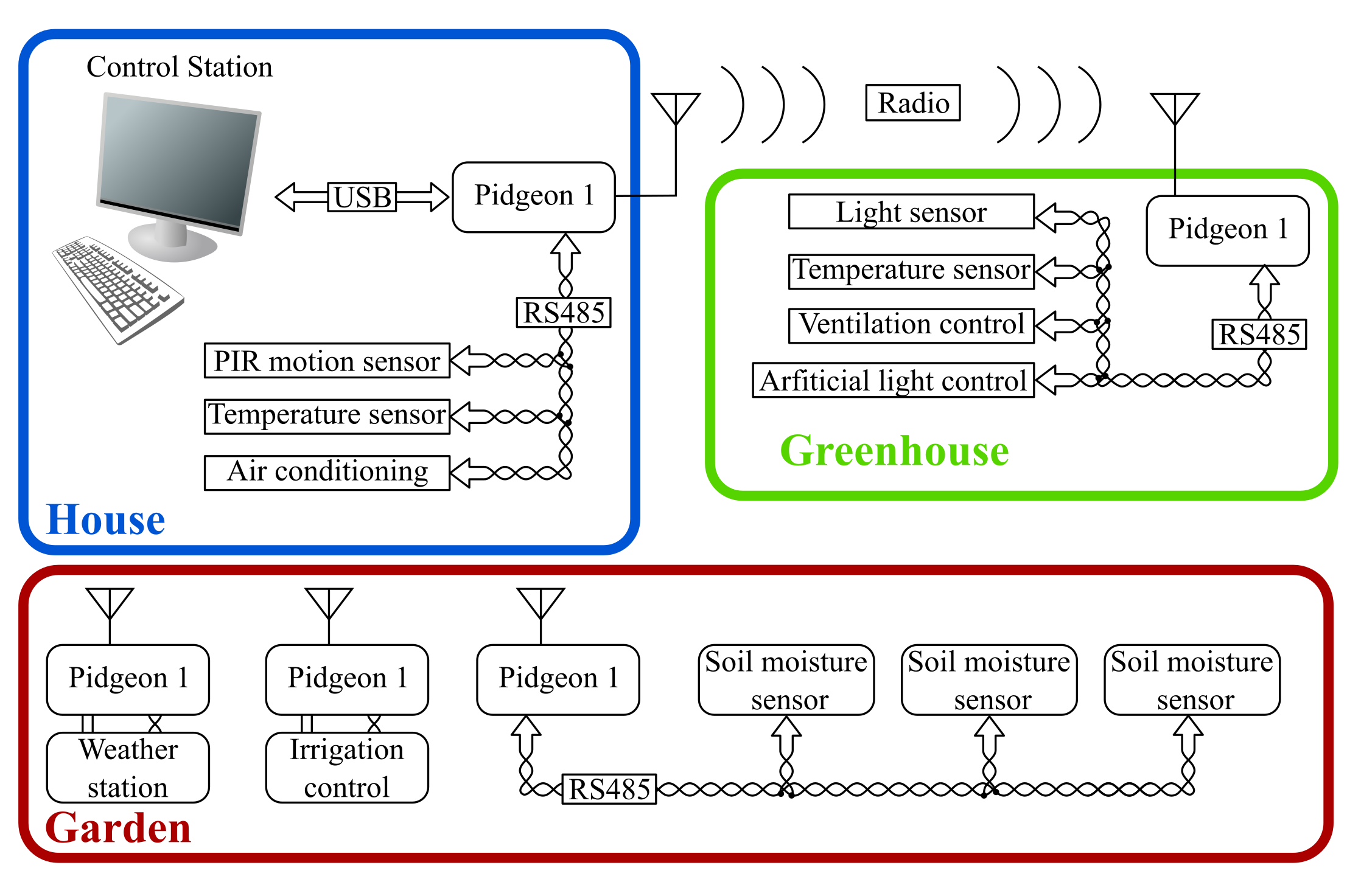
- Wireless sensor network – And of course you can attach sensors over RS485 and control them from the device. ( Example of a network in image below ) Being open allows you to define custom routing, data formatting, compression and pre-proccessing.
![]()
Can you think of other use of this device?
-
FSK variations in RF spectrum analyzer
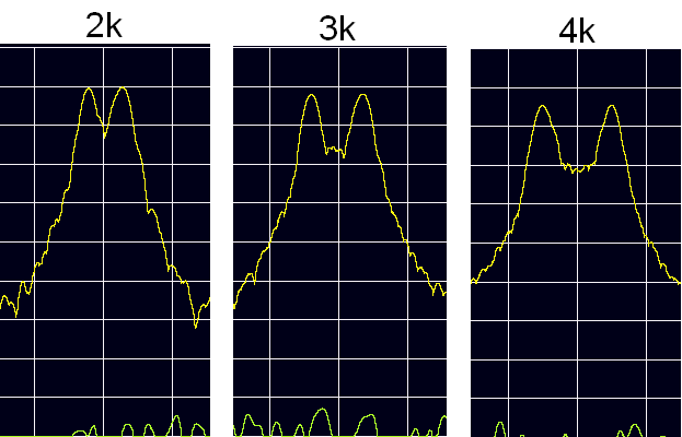
11/25/2016 at 13:24 • 0 commentsNarrowband radio transmission has few key properties. How do they affect transmitted frequency? Let’s take a look on these screen shots from radio spectrum analyzer which show record of maximum received signal strength from transmission of a few packets. Screen shots were taken in regular office therefore variance in amplitude is not related to signal properties as it is result of reflections. Absolute amplitude levels are not shown because of this. Center frequency of the transmission on all images is 868,0125MHz with bandwidth of 8 kHz and bitrate of 600bps. Horizontal resolution of single box is 8kHz.
First tested property was frequency deviation, which describes frequency offset from center frequency during transmission of symbol. In general, the greater the distance between frequencies of different symbols, the easier are they to tell apart (aka. better sensitivity). Max distance is limited mainly by bandwidth which has opposite relation to sensitivity ( less width = more sensitivity ) due to noise. Carson bandwidth rule is often used as rough estimate what deviation and bandwidth to use.
![]()
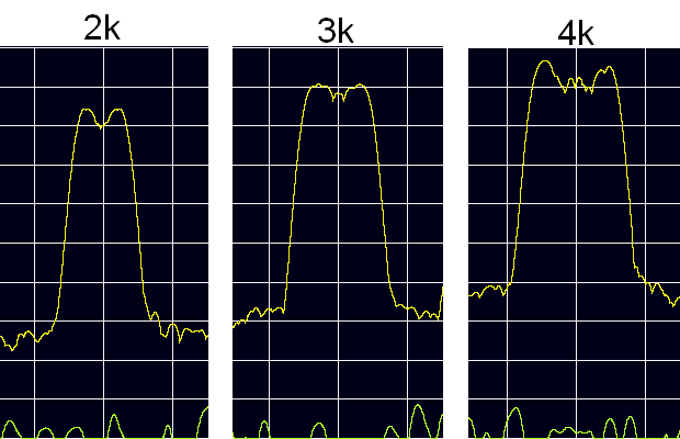
Second observed was the difference between FSK and GFSK modulation. It is expected that the modulation with Gaussian filter should transmit less into adjacent bands. Compare following image which shows the same deviation changes as the previous one except with GFSK modulation.
![]()
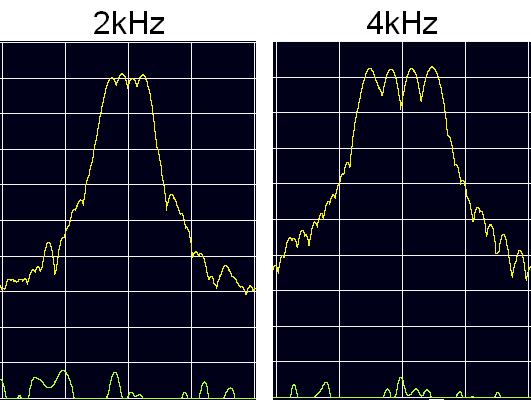
Third interesting property is number of possible symbols ( states ). FSK with 2 states transmits one frequency to sign 0 and other to sign 1. However, CC1120 transceiver also supports 4 state FSK which transmits two bits at the same time requiring 4 distinct frequencies. Doing so increases throughput but decreases sensitivity. 4 peaks are clearly distinguishable in following image at two different deviation settings.
![]()
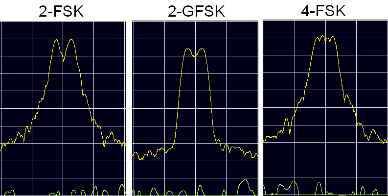
At the end here is a comparison of 2FSK, 2GFSK and 4FSK modulated signal with 2kHz deviation. Not so easy to tell the difference if you don’t know what to look for is it? It would be interesting to test the effect of these settings on datalink range and speed, which would require more devices than exist today. Next goal is therefore fabrication of small batch of the devices.
![]()
( Full images added to project’s files. )
-
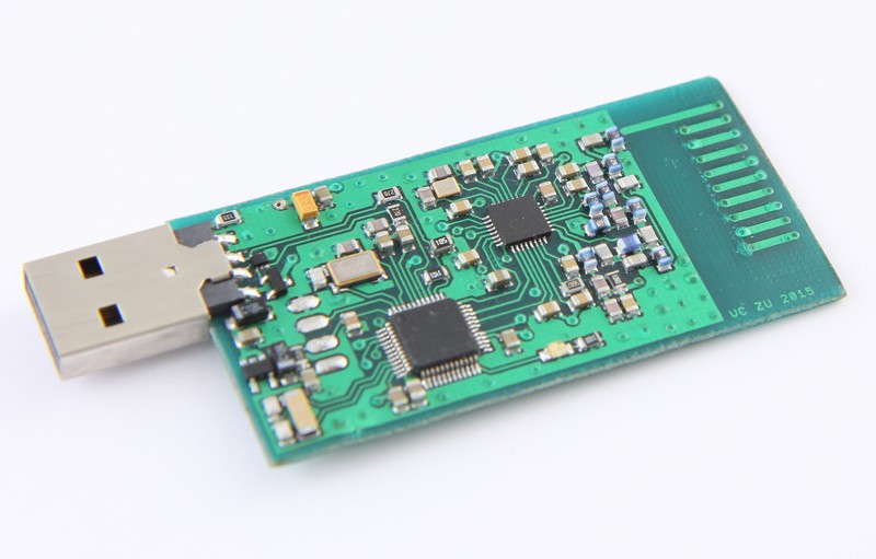
The present
11/21/2016 at 17:19 • 0 commentsThe third version worked in previous recommendations and is being evaluated right now. Important change is replacement of MCU. MSP430 microcontrollers offer very low power consumption which is secured with features like low clock speeds and small RAM and selection of sleep modes. These were the main reason why it has been changed to 32-bit MCU from STM. New MCU has more Flash, RAM, double maximum frequency while allowing faster response times and more tools for compression or encryption. Using the right sleep modes power requirements are not significantly worse, especially compared to those of 500mW transceiver. USB communication is now serviced by FTDI chip and has been tested to work with Windows and Linux systems. This allows new users of STM32 MCU to learn programming from absolute start. It is likely the best to learn peripherals in following steps :
toggle LED (GPIO) → use Timer → use Interrupts → use Serial interface (UART/SPI) → combine known.
This version is also mechanically smaller as it uses 0603 as opposed to 0805 package of passive components. More experiments are in progress with 0402 package. Last change was replacement of LDO regulator for a switching buck converter. The CC1120+CC1190 combo is quite power hungry during full power transmission. Whole device is tested to draw 55mA during reception and 275mA during transmission. Switching converter decreases current taken from 5V rail, but also introduces more noise to 3V3 power rail. Will the noise reduce RX sensitivity? Well … the tests are still in progress. However the power draw has decreased to 40mA during RX and 121mA during TX. (no power-saving features used)
Testing of the 8kHz bandwidth revealed an important issue. Temperature drift. Crystal oscillators have very good frequency stability over temperature. Yet there are conditions where they are unsatisfactory. The third version of the device uses crystal with +-10ppm stability. This means 32Mhz crystal CC1120 requires will over its operational temperature range ( -20° C to +70° C ) change frequency by no more than 320Hz up or down. Creating for example 868MHz requires multiplying the 32MHz by a little over 27. Temperature error is also multiplied which brings max error above the whole bandwidth. ( 8690 Hz ) Also not to forget is that this drift goes in either direction causing whole temperature delta to be 17kHz. To reliably receive signal with 8kHz bandwidth, the receiver has to use 25kHz bandwidth. While there are software methods of temperature compensation there is also an easier way of using directly temperature compensated oscillator. After swift peak at the market I’ve found these oscillators at comparable price to the bare crystal have stability of just +-2ppm. More expensive models can easily go below +-0.5ppm. This greatly reduces the problem to the level where crude temperature measurement of MCU with resolution of about 10° C would be enough to suppress any effects of the drift. Practical testing with +-10ppm crystal and 8kHz bandwidth at both devices showed 15° C delta is enough to disrupt the datalink. If both devices are in the same environment temperature drift is not an issue. Its a different story if, for example one device is indoors and other is outdoors. Next version will therefore use TXCO with hopes no or minimal software compensation will be required.
-
The past
11/14/2016 at 19:15 • 0 commentsThe first prototype of the device used quite different IC’s. Originally it was intended for wireless control of “toys” and robots from notebook, for which wifi’s range was insufficient. Thus the range and size of CC1120 transceiver combined with PCB antenna was acceptable. PCB antenna design originated from manufacturer’s (Texas Instruments) recommendations. Compared to simple wire with quarterwave length it was only slightly more directional with mildly lower range ( 200meters for wire and 160meters for PCB. Both at open field at 1,2kbps ).Core of control used to be MSP430 microcontroller, which handled both RF module and USB connection. Main algorithm was derived from TI’s USB stack, which is heavily oriented towards low power consumption. It was quite a challenge to resolve conflicts between service routines of USB communication and of RF module as almost every USB related call ended with sleep mode activation. Another inconvenience was the need to install custom driver on Windows computer.
![v1]()
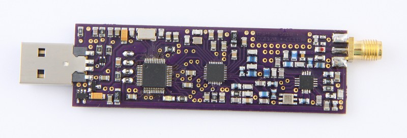
The second iteration has risen from the need to use the device as data collector from wireless sensor nodes. Nodes were located in the forest so range became issue again. Radio was enhanced with CC1190 front end and PCB antenna was replaced with SMA connector. This improved the line-of-sight range with quarterwave length wire to 500meters at 4,8kbps. At this point code size reached free compiler limit of 16kB. USB stack was to blame requring 9kB. (without optimizations, as they had issues with RF module) It probably is possible to rebuild the USB stack for GCC compiler to overcome size limit. However, it wouldn’t help in the long run so I rather scheduled next revision to have separate USB controller.
![v2]()
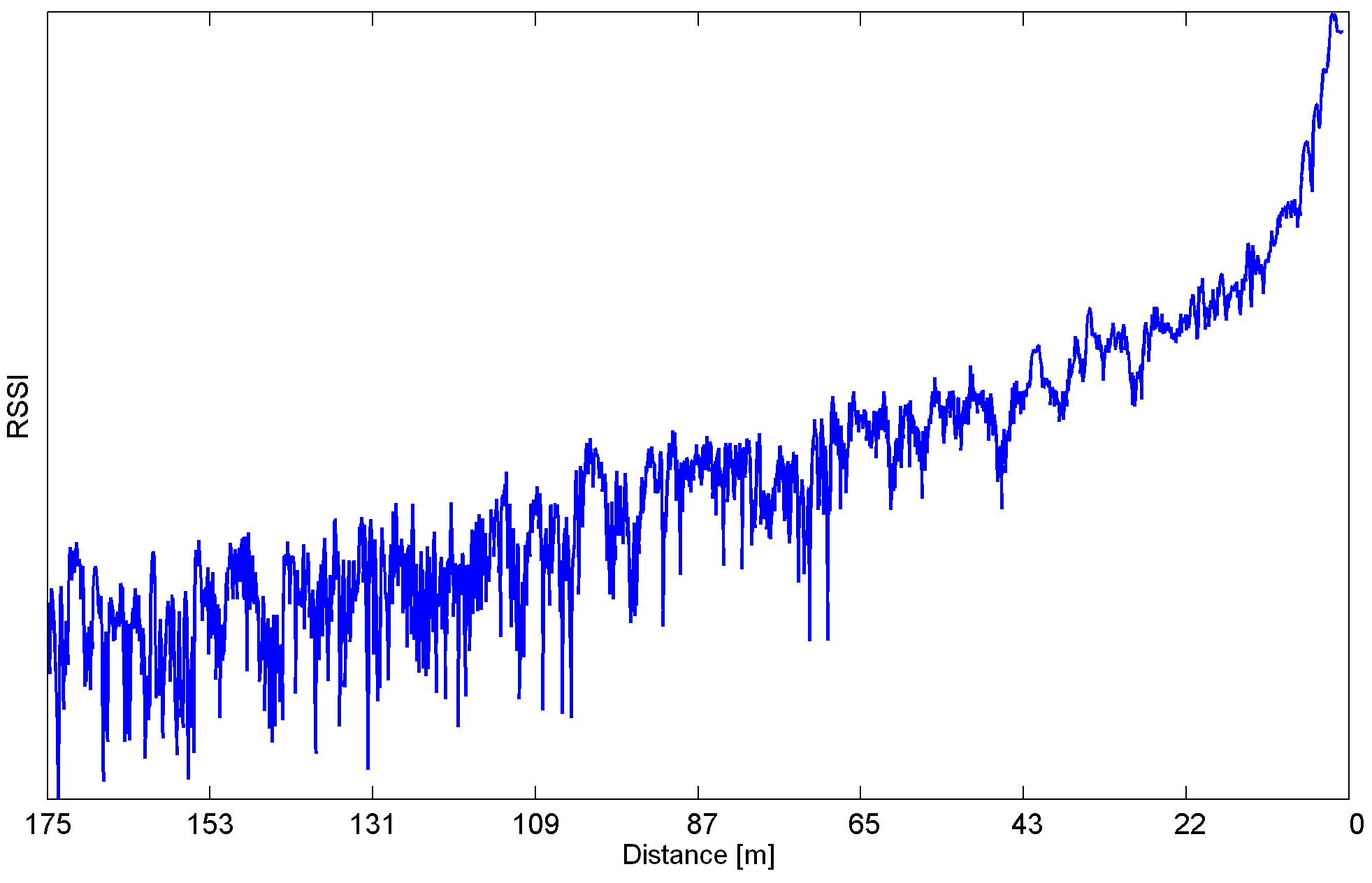
The CC1120 transceiver was also used as part of my final thesis at university for estimate of users position based on received signal strength. Experienced or even average radio enthusiast would know the radio signal in real environment reflects, which can cause changes in received signal strength (multipath propagation). These changes depend on the specific environment and not on the distance from transmitter. But how exactly does the signal change? Can it be filtered?
The following graph is a raw record of RSSI while user walks directly towards transmitter. Measurement took place on an empty street near park with various sources of reflections.
![]()
Few peaks and valleys are clearly visible. They seem to have a potential to cause 40 meter error in distance estimate, which is a lot for device with 175meter range in tested environment. There are ways to decrease this error, but that is unrelated to the RF dongle. Experiments like this can be done with the device. Software access to elementary properties of RF transmission can be quite useful.
Open narrowband RF transceiver
No more restrictions from high level software! Access the lowest level of radio transmission with this programmable USB stick.