-
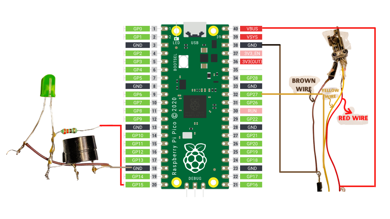
11Now Interfaced the buzzer, led and trigger push button to the Pi Pico
- The long leg of LED & Buzzer ➡ GP15 (Pico)
- Short Leg of Led & Buzzer ➡ GND (Pico)
- Brown Wire Pin of trigger push button ➡ GND (Pico)
- Yellow Wire Pin of trigger push button ➡ GP27 (Pico)
- Red Wire Pin of trigger push button ➡ VBUS (Pico)
![Complete circuit diagram Complete circuit diagram]()
-
12Set up the Software
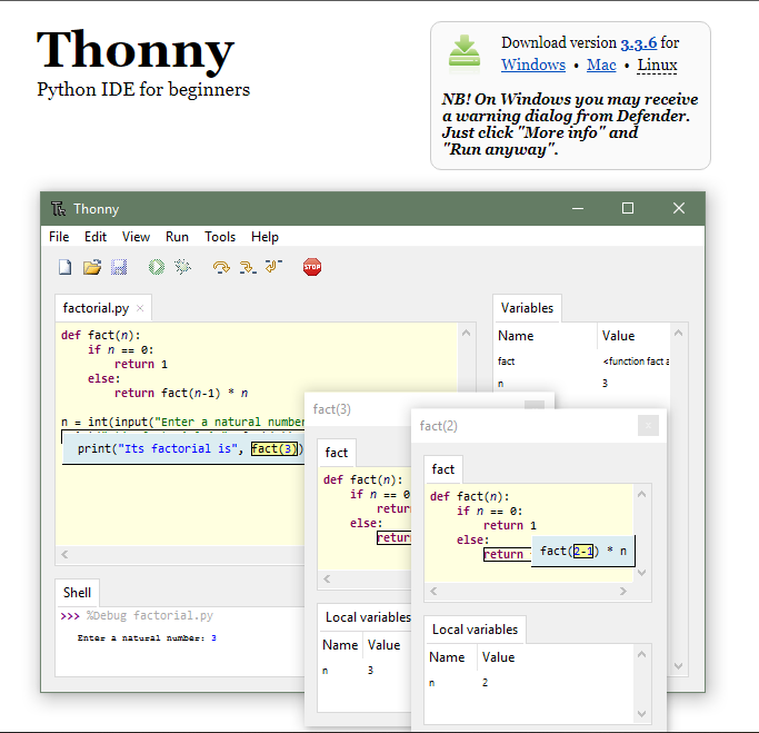
Now we are using the Thonny Python IDE for giving the instruction to the pi pico, so that when we trigger the push button the desired action can perform
- Download the Thonny Python IDE using this link
- Install it in your machine
- Download the Thonny Python IDE using this link
-
13Install the CircuitPython firmware into pi pico
- Download the CircuitPython UF2 by using this link
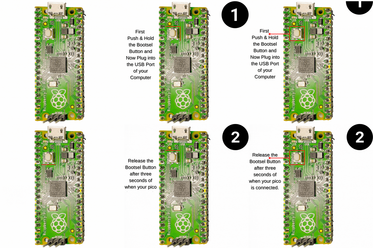
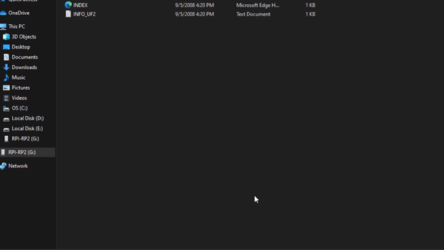
- Push and hold the BOOTSEL button and plug your Pico into the USB port of your computer. Release the BOOTSEL button after your Pico is connected.
![Install the circuit python Install the circuit python]()
- Download the CircuitPython UF2 by using this link
-
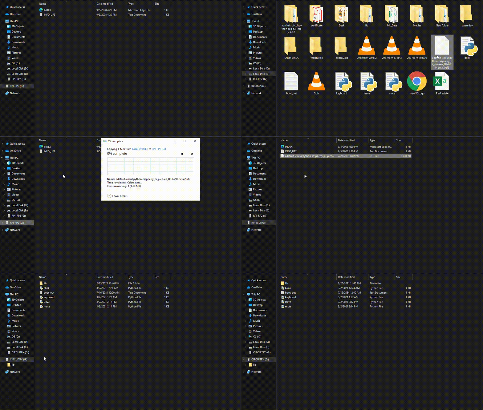
14Pi Pico Will Mount As a Mass Storage Device Called RPI-RP2 in Your Computer
-
15Reboot Your Pi Pico for the Circuit Python
- Drag and drop the CircuitPython UF2 file onto the RPI-RP2 volume. Your Pico will reboot. You are now running CircuitPython.
![Drag and drop the firmware Drag and drop the firmware]()
-
16Add the Adafruit Circuit Python Hid Library
Now add the adafruit_circuitpython_hid library for adding the keyboard and mouse capabilities into the pi pico. Download the library by clicking the below button.
- Download the library by clicking this link
- Inside the library folder, copy the lib folder
- Now paste this folder into the pi pico volume.
-
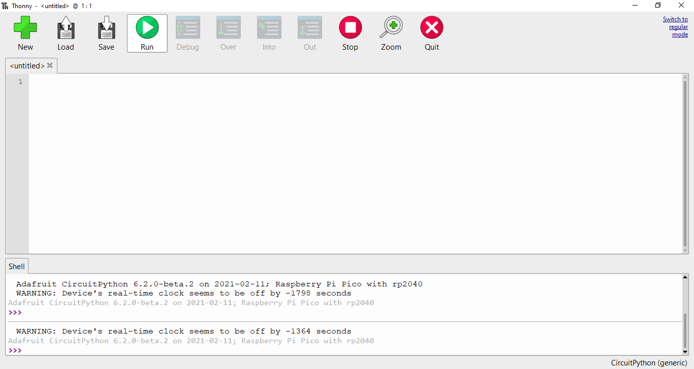
17Now open the Thonny IDE. And choose the CircuitPython port
-
18Code
Write the below code and save the file with the name of code.py. (If you are saving the file with another name then in that condition you will have to upload the code each time when you plugged the pi pico
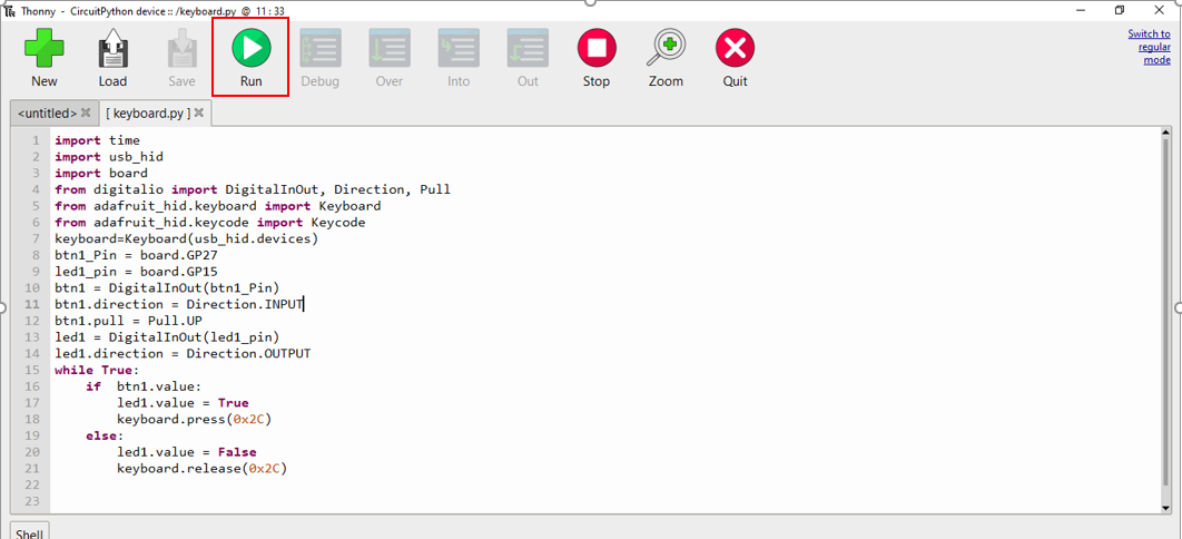
import time import usb_hid import board from digitalio import DigitalInOut, Direction, Pull from adafruit_hid.keyboard import Keyboard from adafruit_hid.keycode import Keycode keyboard=Keyboard(usb_hid.devices) btn1_Pin = board.GP27 led1_pin = board.GP15 btn1 = DigitalInOut(btn1_Pin) btn1.direction = Direction.INPUT btn1.pull = Pull.UP led1 = DigitalInOut(led1_pin) led1.direction = Direction.OUTPUT while True: if btn1.value: led1.value = True keyboard.press(0x2C) else: led1.value = False keyboard.release(0x2C) -
19Now run the code by clicking on run button at the top
-
20Now check that all is working fine before placing the hardware inside the Gun
Turn Your Old Zapper Gun into meeting controller
Hi, makers, we are going to transform the old zapper gun, into a meeting controller or chrome dino game controller.
 Narayandojo Stemclub
Discussions
Become a Hackaday.io Member
Create an account to leave a comment. Already have an account? Log In.