 teru
teru-
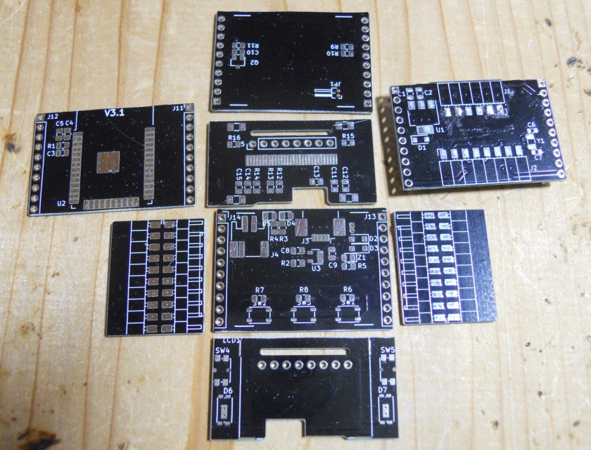
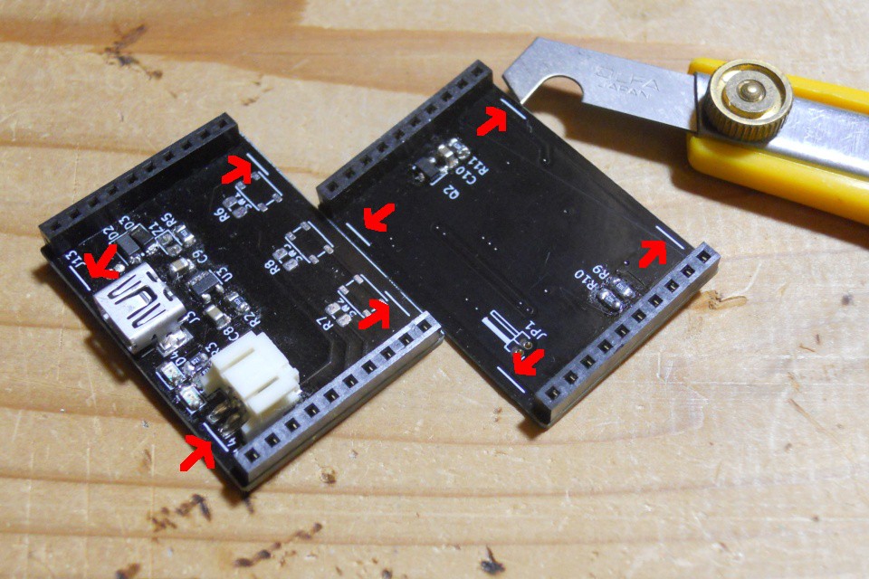
1Cut PCB
First of all, cut PCB along white line.
![]()
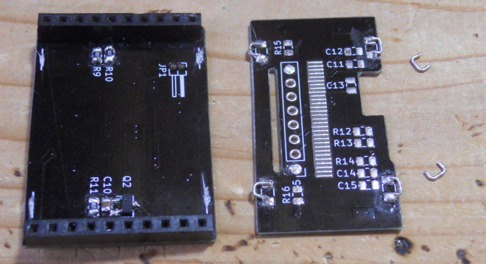
Below is separeted and arranged boards
![]()
-
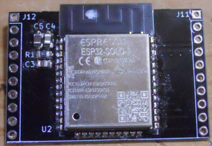
2MCU board
Solder ESP32 module, decaps and reset circuit for EN pin on top of board.
![]()
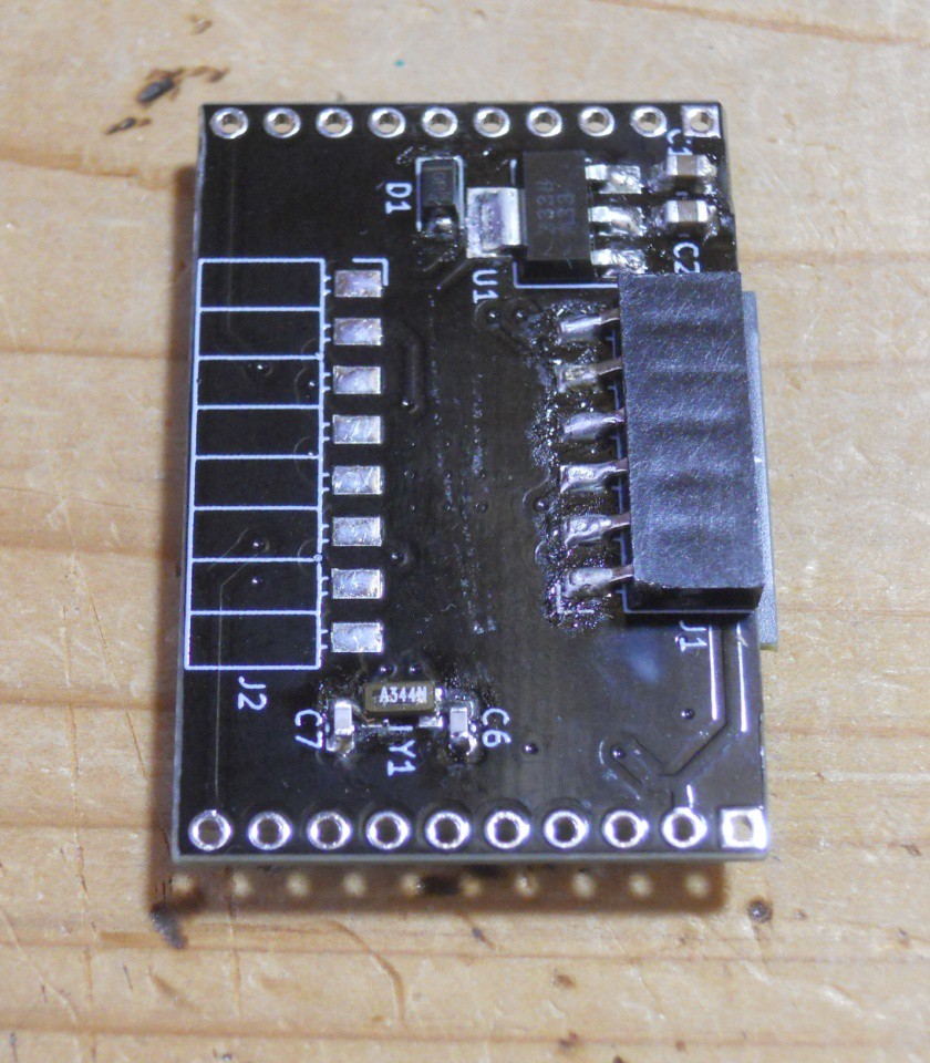
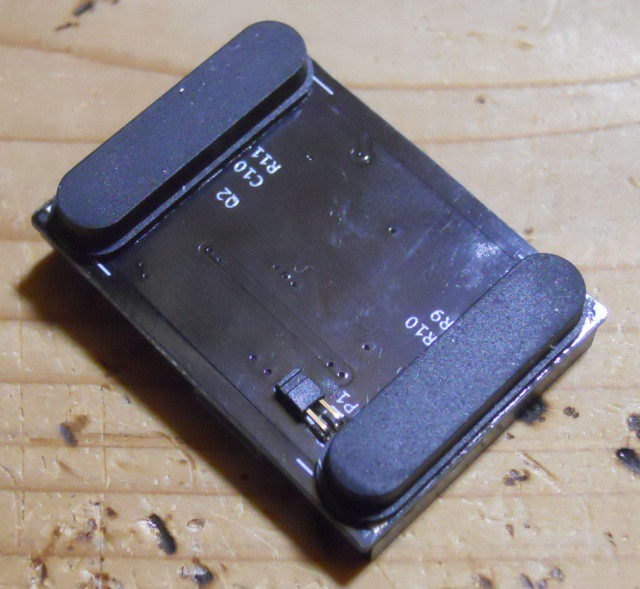
Solder 3.3V regulator, 32768Hz clock crystal, capacitors and pin socket to program ESP32 at bottom of board
![]()
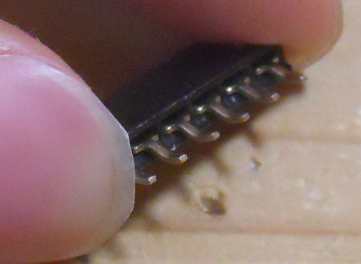
I could't find SMD right angled pin socket of this size, I bent leg of socket so that it looks as if a SMD socket.
![]()
then solder pinheader at left and right side. Remaining pad to solder pin socket to connect front panel will be soldered later.
Now you can check if ESP32 works.
-
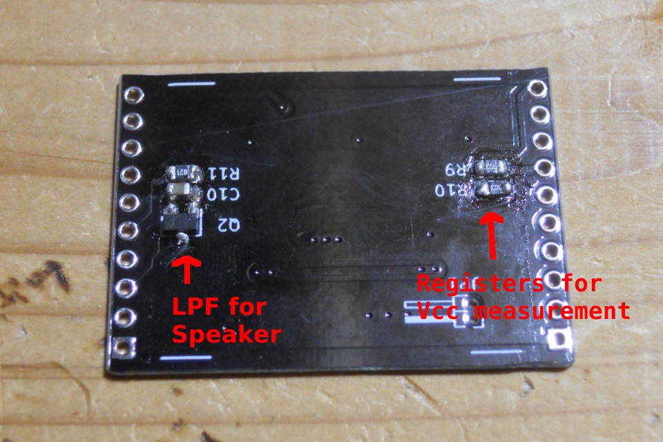
3IO board
Solder resistors, capacitor and transistor at bottom of board.
![]()
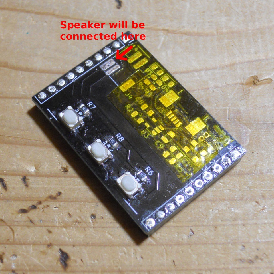
Solder switches and pull-up resistors on top of board.
Cut leg of sockets to slightly less than board thickness before soldering so that the leg does not scratch fingers.
![]()
I covered unused pads with tape so that they don't interact with speaker when I placed on.
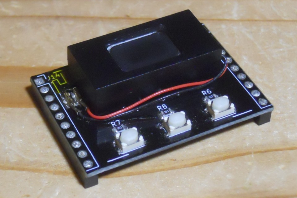
Solder speaker contact and adhere speaker to board.
![]()
-
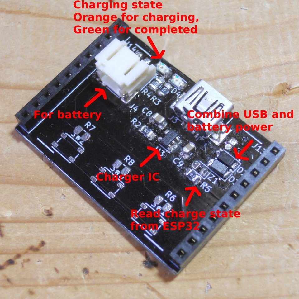
4PSU board
It would be better to solder the USB mini-B socket first. This socket is only for power and signal pins are not connected.
The leg of the socket is hiding under housing and I could not hand solder it well :-(Then solder charger IC (MCP73831) and other resistors, capacitors and LEDs.
Then solder PH socket for battery, and pin sockets at left and right sides
Note to cut leg of pin sockets just like done for IO board, but different reason - I am going to add rubber foot at bottom of the board.![]()
Solder right angle pin header at bottom. This is used as power switch.
![]()
Adhere rubber foot with double-sided tape. This fits nicely and hides pads!
![]()
-
5side panels
Side panels are simple. Just place parts precisely or it might not build up well. I taped it to do so.
![]()
-
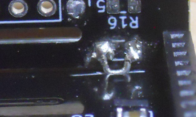
6back panel
There is no component to be soldered to back panel.
But I filled unused TH with solder. Also solder 4 bars.![]()
-
7display board
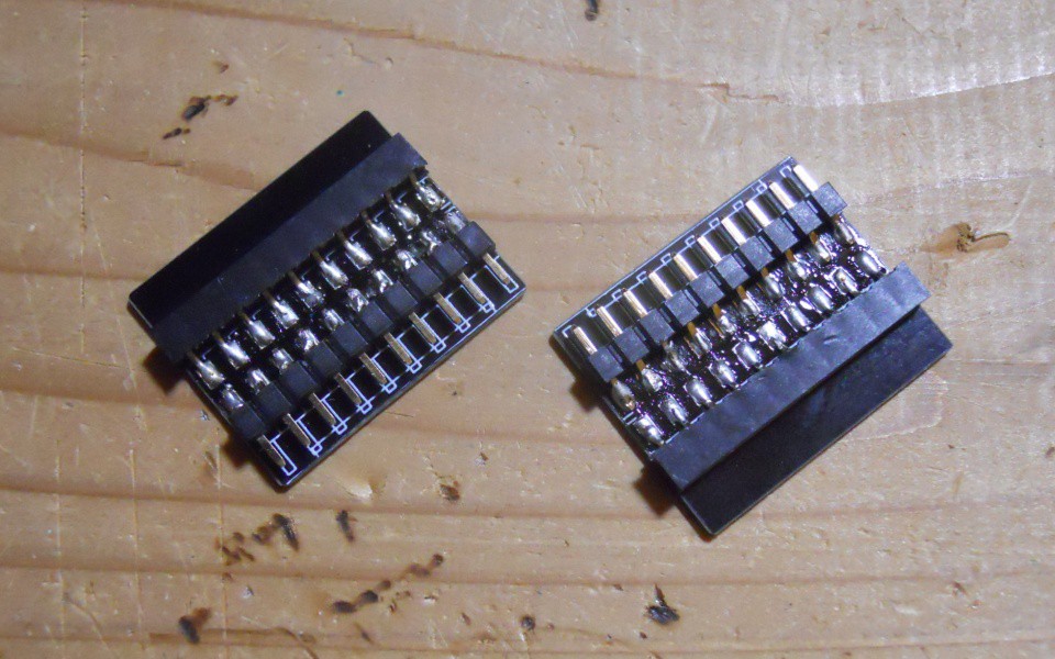
Solder pin socket to MCU board. To solder at correct location, holding boards "connected" while soldering. I bent leg of pin socket 180 degree btw.
![]()
Then solder pin header to display board. It may be easier to solder if you attached top, side and bottom boards to MCU board when soldering, which also helps to position.
Note that it is critical to make resulting surface flat to mount OLED pannel.![]()
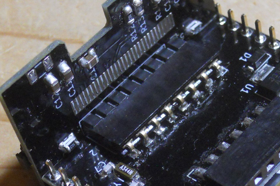
Solder capacitors and resistors required to drive OLED.
![]()
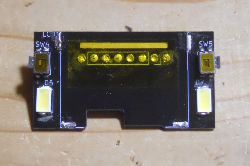
Optionaly solder LEDs, switches and resistors to drive the LEDs.
These LEDs are only turned on by connected switches(not connected to MCU). I added these to just fill blank space.![]()
-
8Adding holder
front/back panels are not connected strongly. So I needs to add bars to support panels are fixed.
Add 8 valleys to top/bottom boards along straight silk marks where bars of front/back panels to be inserted.
![]()
Below picture is when I done adding valleys to top board for back panel.
![]()
![]()
-
9Attach OLED to display board
Finally, attach OLED to display board. I think it is better to do this as last step to prevent OLED from being damaged by heat.
Solder bezel over OLED panel to fix OLED panel to display board. 4 arrows in below picture indicates soldering point. I also hope the bezel protect from physical damage but not sure. Use double-sided tape instead if you prefer.
![]()
Solder FPC connector.
![]()
ESP32 Small Alarm Clock
Small alarm clock with ESP32 module, 0.96" OLED panel and small speaker.


Discussions
Become a Hackaday.io Member
Create an account to leave a comment. Already have an account? Log In.