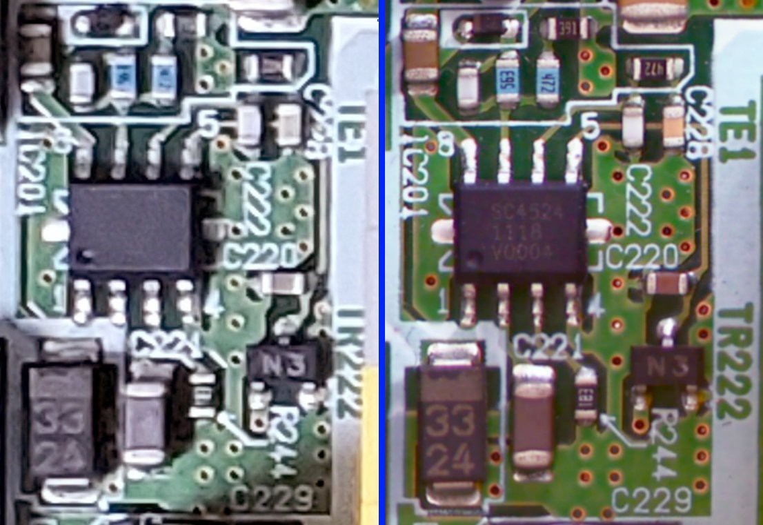
I've been playing a lot with my new "toy" and it performs better than I expected. Here is a little comparison of the kind of details I can obtain with it:

Left is from the photo I took with my Galaxy S10, right from one took with my document camera. Note that I didn't set the document camera zoom to its maximum when taking this photo, which means that at full zoom I could have a photo with even more fine details.
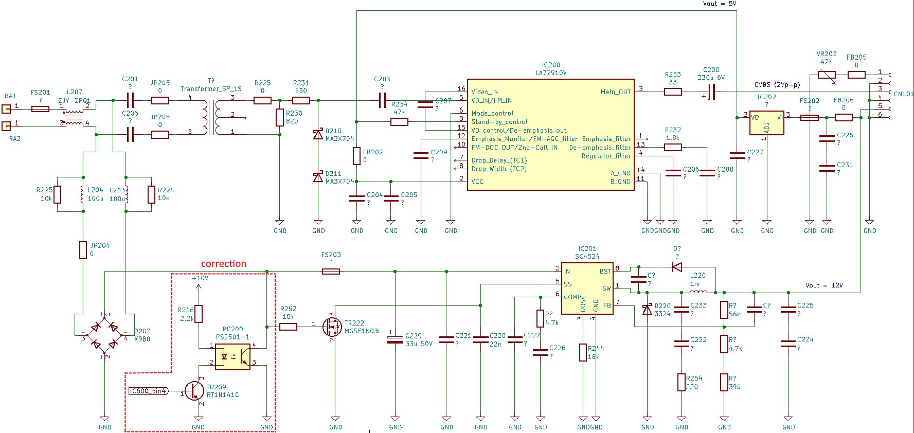
Yesterday, I spent some time photographing the front and back of the video intercom PCB. I set the document camera zoom at almost its maximum and ended up with more than 100 photos to stich together. For that, I used Image Composite Editor which managed to stich everything together perfectly after just a few tweaks. In Paint.net, I deformed a little bit each photo so that both side vias and through holes aligned perfectly and then proceeded to check my previous board reverse engineering work. I found out that I missed some very important connections:

As seen in the above picture, IC201 that powers the video demodulating IC200 and the display module with 12V DC is enabled/disabled by IC600, which is a 8 bit CMOS microcomputer (a M38039G4HHP made by RENESAS). The new Kicad schematic can be found in the FILES section.
 Florian
Discussions
Become a Hackaday.io Member
Create an account to leave a comment. Already have an account? Log In.