 Florian
I certainly took my time but after long hours of tracing PCB tracks in Paint.net, identifying components and putting everything together in Kicad I finally ended reverse engineering the 2 PCBs there is in this video intercom.
To help me achieve my others objectives I then proceeded to identify which portions of the schematic where responsible for dealing with:
- the audio coming from the entrance panel and going to the room monitor speaker
- the audio coming from the door unit and going to the same room monitor speaker
- the audio of the room monitor microphone and sending it to the entrance panel
- the audio of the room monitor microphone and sending it to the door unit
- generating the chime and sending it to the room monitor speaker but also to the door unit
For the sake of clarity, for each of the above I created a simplified schematic with only the components and connections that seemed to be relevant and compiled those 5 schematics in one big Kicad file (see FILES section for download).
Here is for example the portion of the overall schematic that deals with 1.
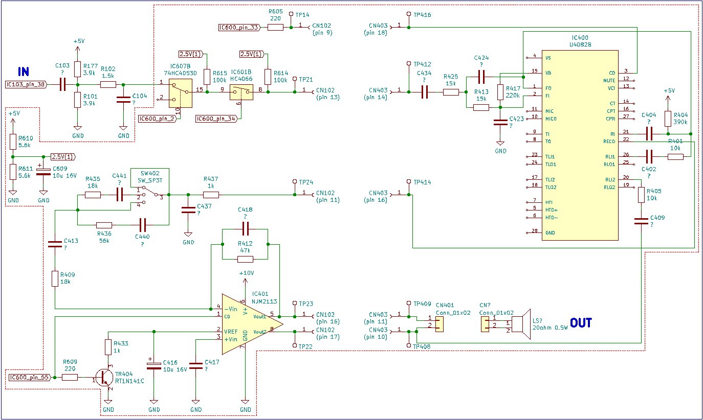
Thanks to those simplified schematics, I now have a pretty good idea of how this video intercom works and where in the future I should connect to in order to record the audio going between the entrance panel, door unit and room monitor. Also where to connect in order to inject a signal audio and have it played by the entrance panel or door unit.
While tracing back PCB tracks, I noticed that apart from the video signal, the remaining data and audio signals are going directly into a big IC branded with the manufacturer name (that I wasn't able to identify). Certainly a custom IC but next to it is the microcomputer (the one I referred to in my previous log) and after a close inspection, I found traces going only between those 2 ICs... so I guess they talk to each other?
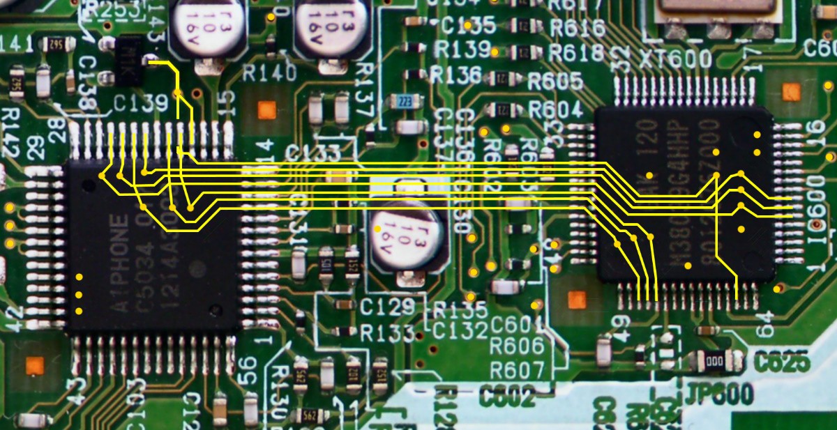
I went through the microcomputer datasheet and checked the main function of each of the connected pins and it looks promising:

Next course of action will be to add some wires here and there so I can easily connect my logic analyzer or oscilloscope. Then probe for signals in situ, to confirm a few of my hypothesis but also learn what those 2 ICs are saying to each other.
Discussions
Become a Hackaday.io Member
Create an account to leave a comment. Already have an account? Log In.