-
New panel, new stock!
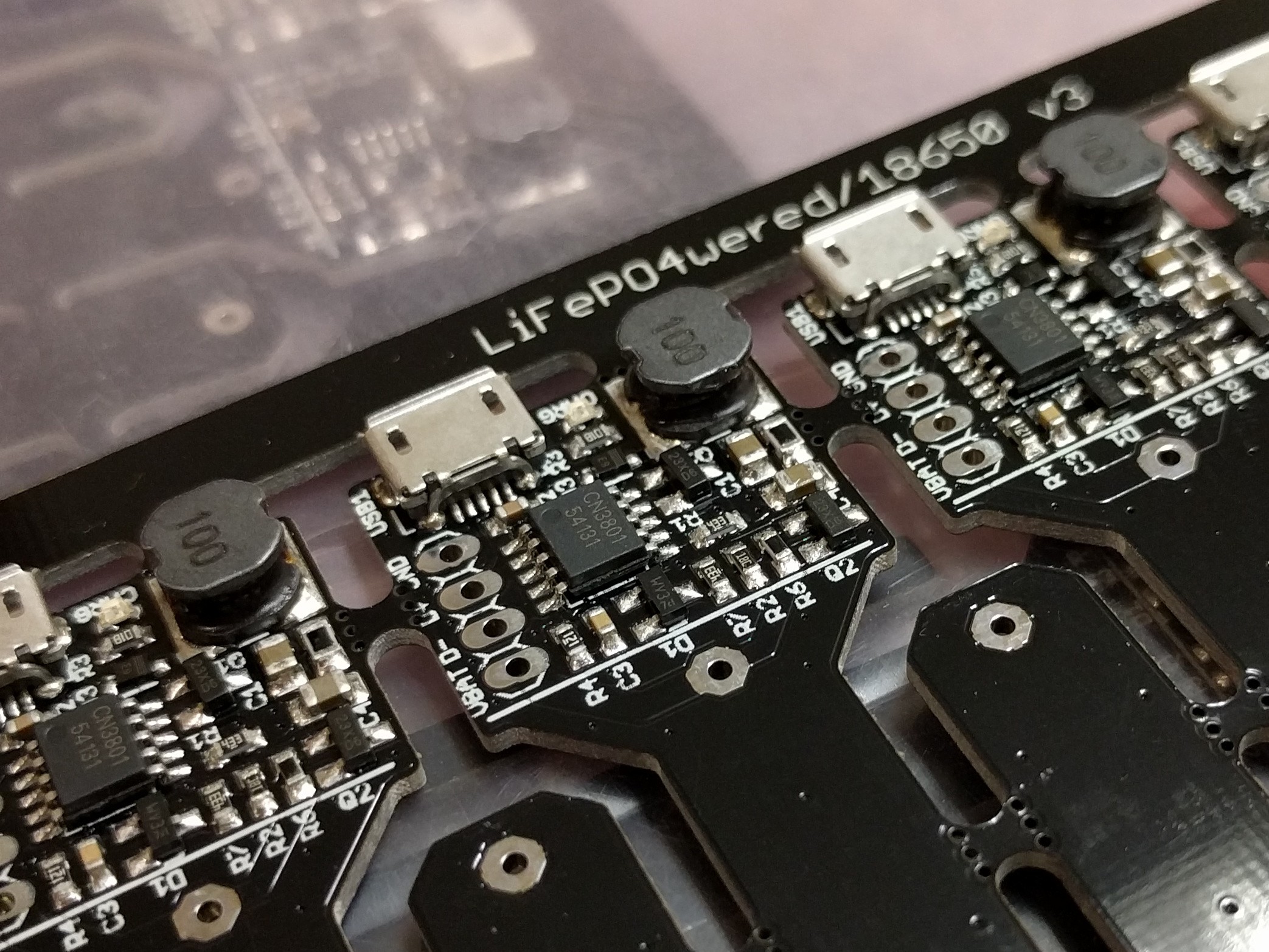
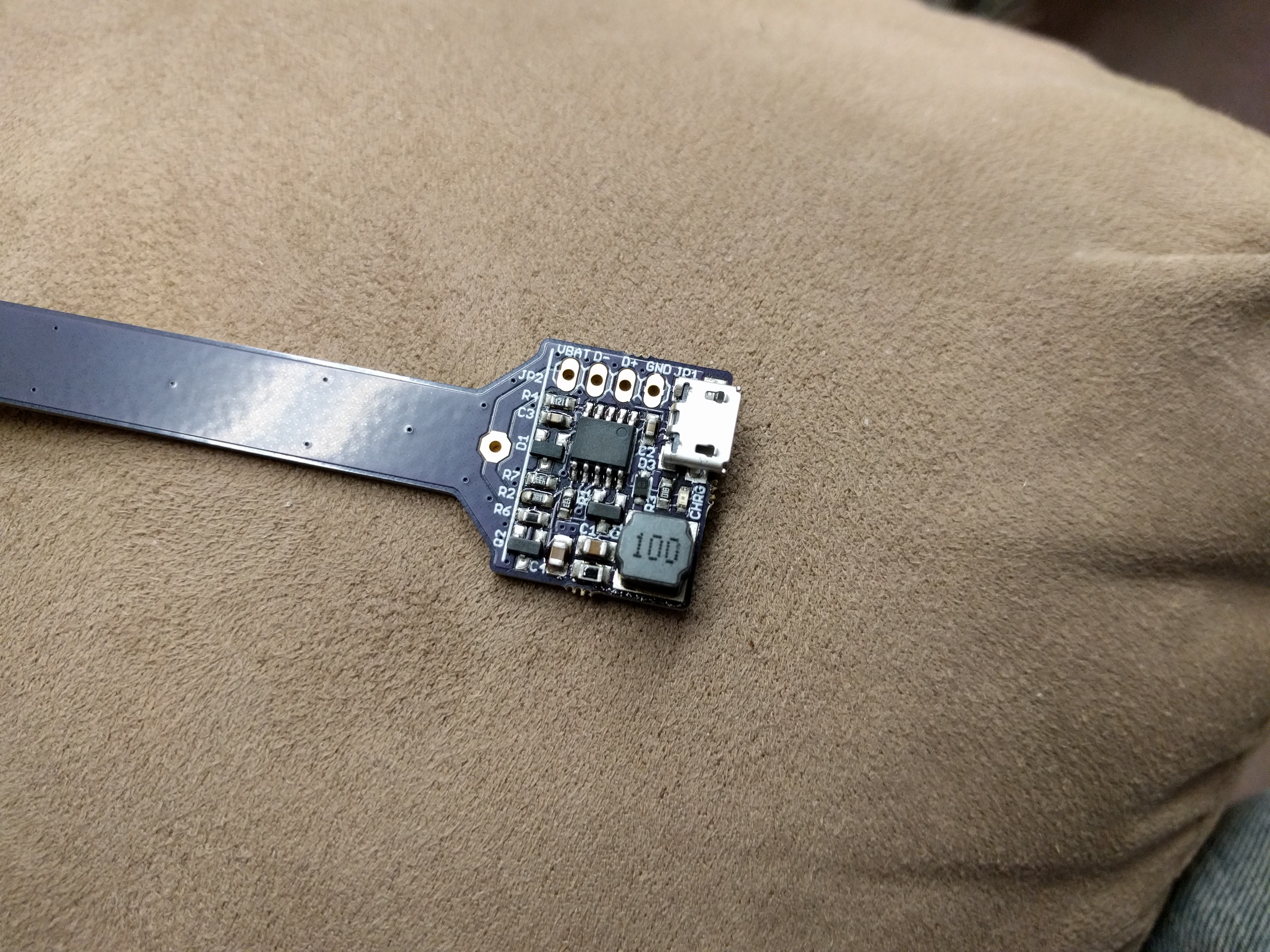
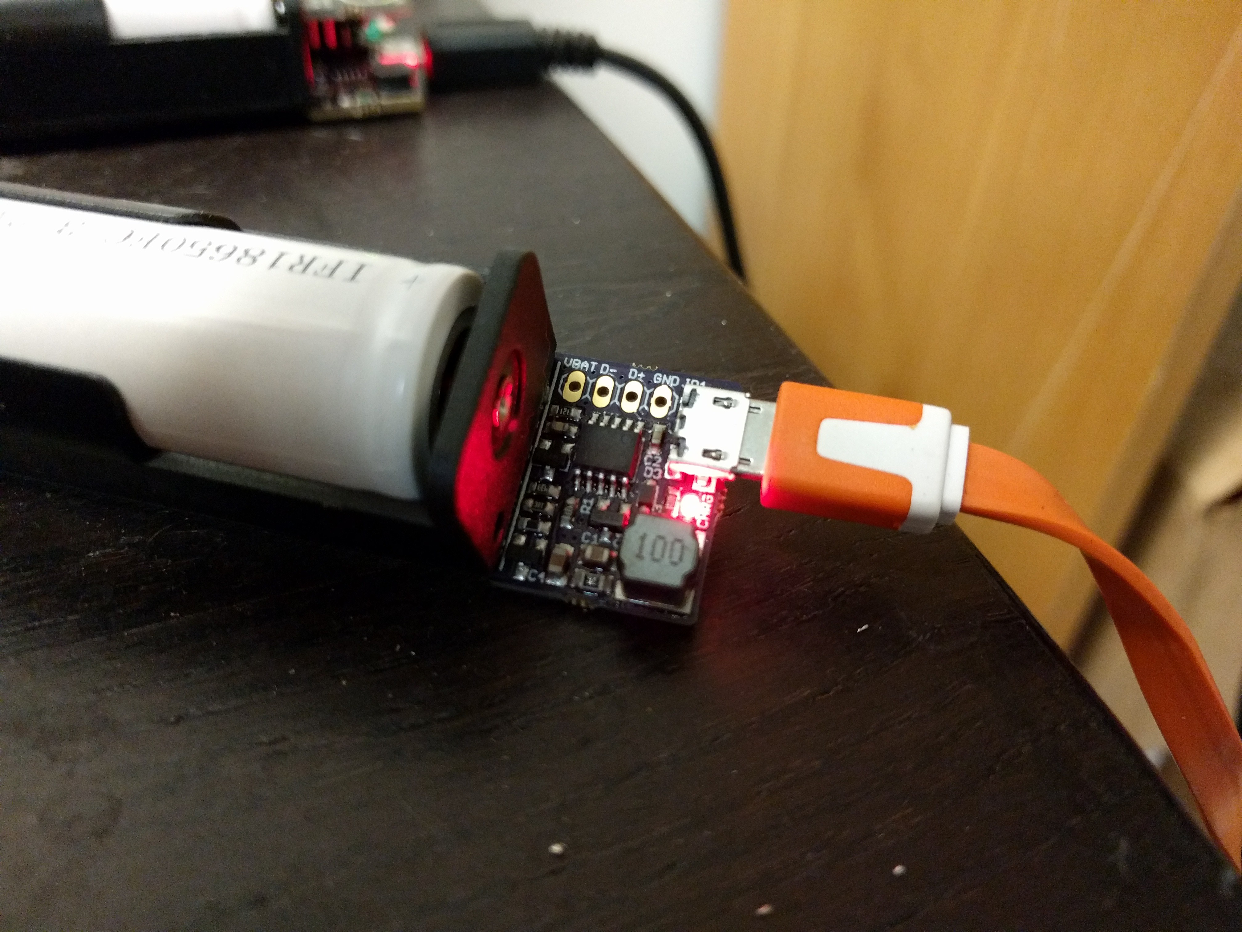
07/14/2017 at 16:59 • 0 commentsI had run out of my first PCB run of panels so I decided to do a quick improvement before ordering new ones. I had noticed that some of the surface mount USB connectors were mounted slightly crooked. Nothing major, but still something that nags on a perfectionist like me. ;) So I switched to a different USB connector that has alignment features going into the board to help keep it straight. I'm very happy with the results:
![]()
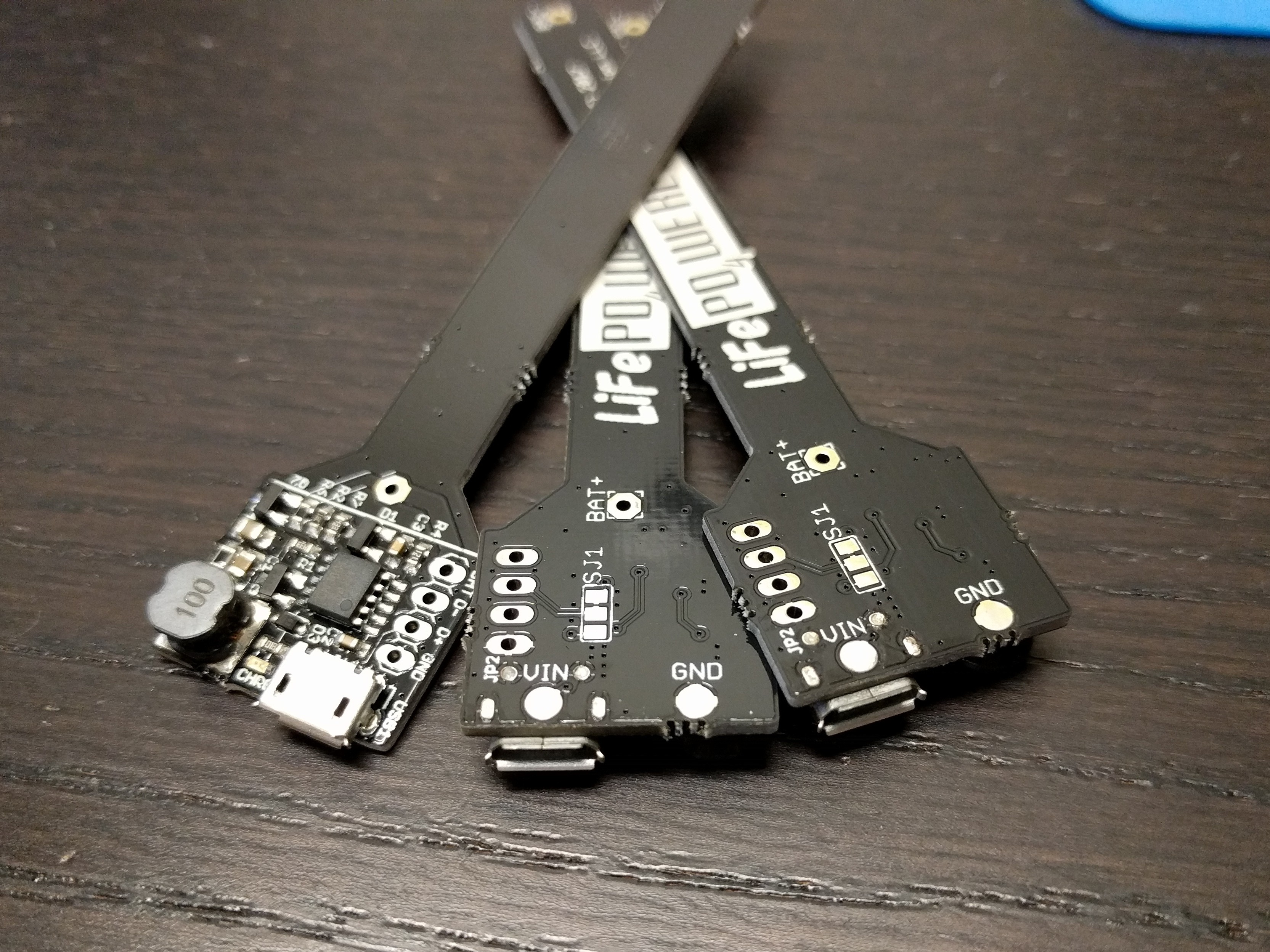
No more crooked connectors! One side effect is that the alignment features are through hole, and the holes interfered with the original location of the VIN and GND connection pads on the bottom of the PCB. So I had to move them to work with the new layout:
![]()
I think there is enough clearance between the VIN pad and the USB connector holes (that are ground) to not cause a problem, but just a heads up to those using the VIN pad to take care with their soldering. :)
I have a couple of units of the old design left but all new stock after that will have these improved connectors!
-
In production!
12/20/2016 at 21:31 • 0 commentsThe LiFePO4wered/18650 is now in production! Here's a video of the panels being built at Colorado Tech Shop:
Since I primarily designed it as a new base for the #LiFePO4wered/Pi, this combination is for sale now on Tindie as the LiFePO4wered/Pi3. It's not yet for sale as a LiFePO4 charge module on its own like the #LiFePO4wered/USB, but I plan to do so soon. The problem is mostly that the documentation is not yet done. :)
In the mean time, you can get it touch with me directly if you want to buy some for your projects.
-
Solar power!
12/12/2016 at 19:25 • 1 commentOne really neat feature of the LiFePO4wered/18650 that I haven't talked much about is the ability to power it from a 5-7V solar panel. I've only been able to test this just now because the component reel I was waiting for makes it possible to do this, since now the input cap is rated for 16V instead of 6.3V.
The charge controller I used has MPPT functionality with a fixed voltage set point. This means that the charger will reduce charge current to prevent the input voltage from sagging below this voltage. On the LiFePO4wered/18650 I have set this set point to 4.66V, which is a pretty decent value (not optimal but usable) for small 5-6V solar panels.
At the same time, this feature also makes it so the LiFePO4wered/18650 can dynamically adjust to the actual output capacity of a USB charger. Although reaching a maximum charge current of 1.33 A when connected to a powerful 2A USB charger, it will not overload a less capable power source such as a computer USB port. The charger will just limit the charge current when the voltage starts to droop. This is why the MPPT set point is at 4.66V: a USB power source's minimum voltage can be 4.75V so we need some headroom.
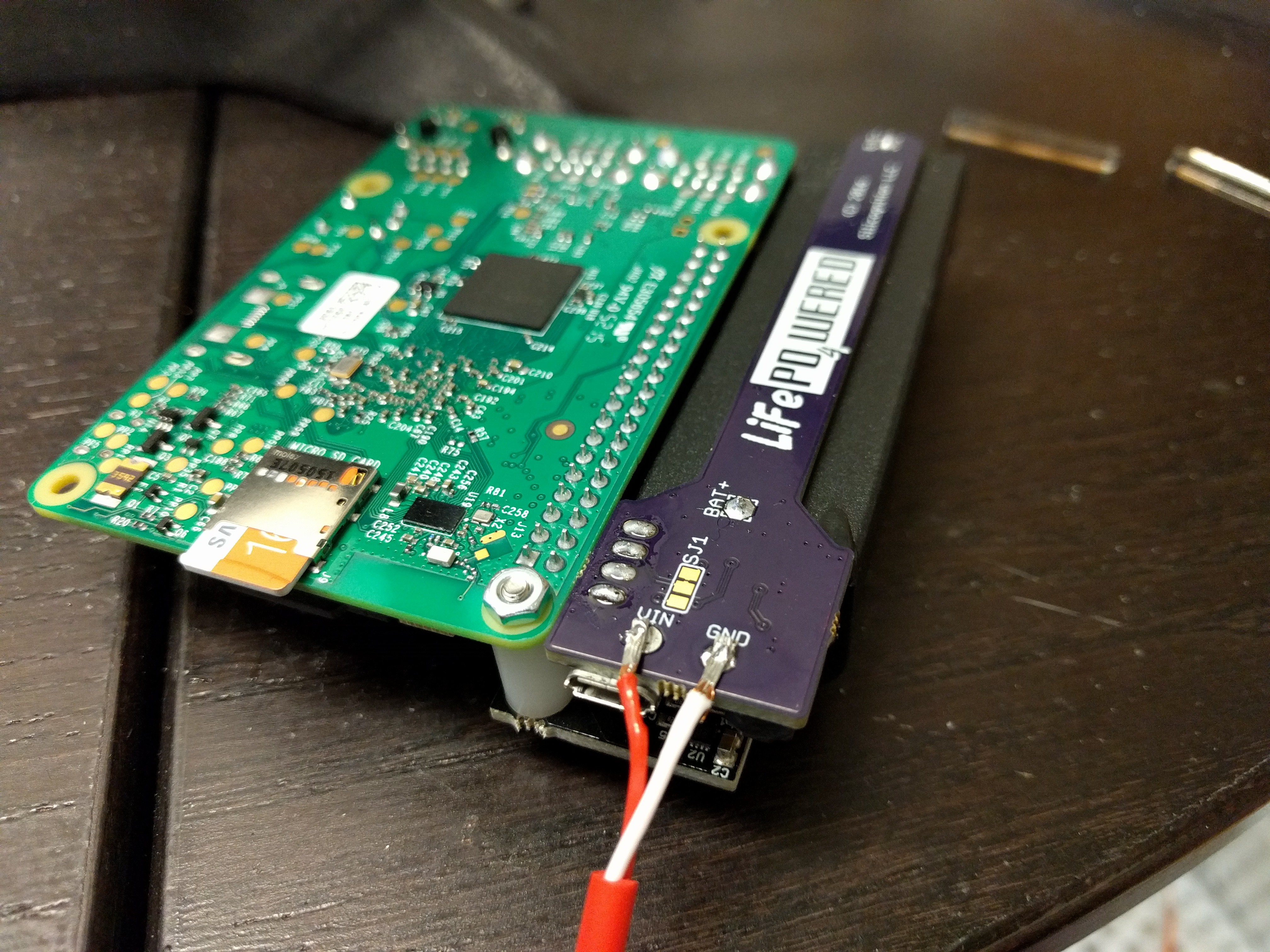
The LiFePO4wered/18650 has convenient solder pads on the bottom where you can connect an input source other than micro USB:
![]()
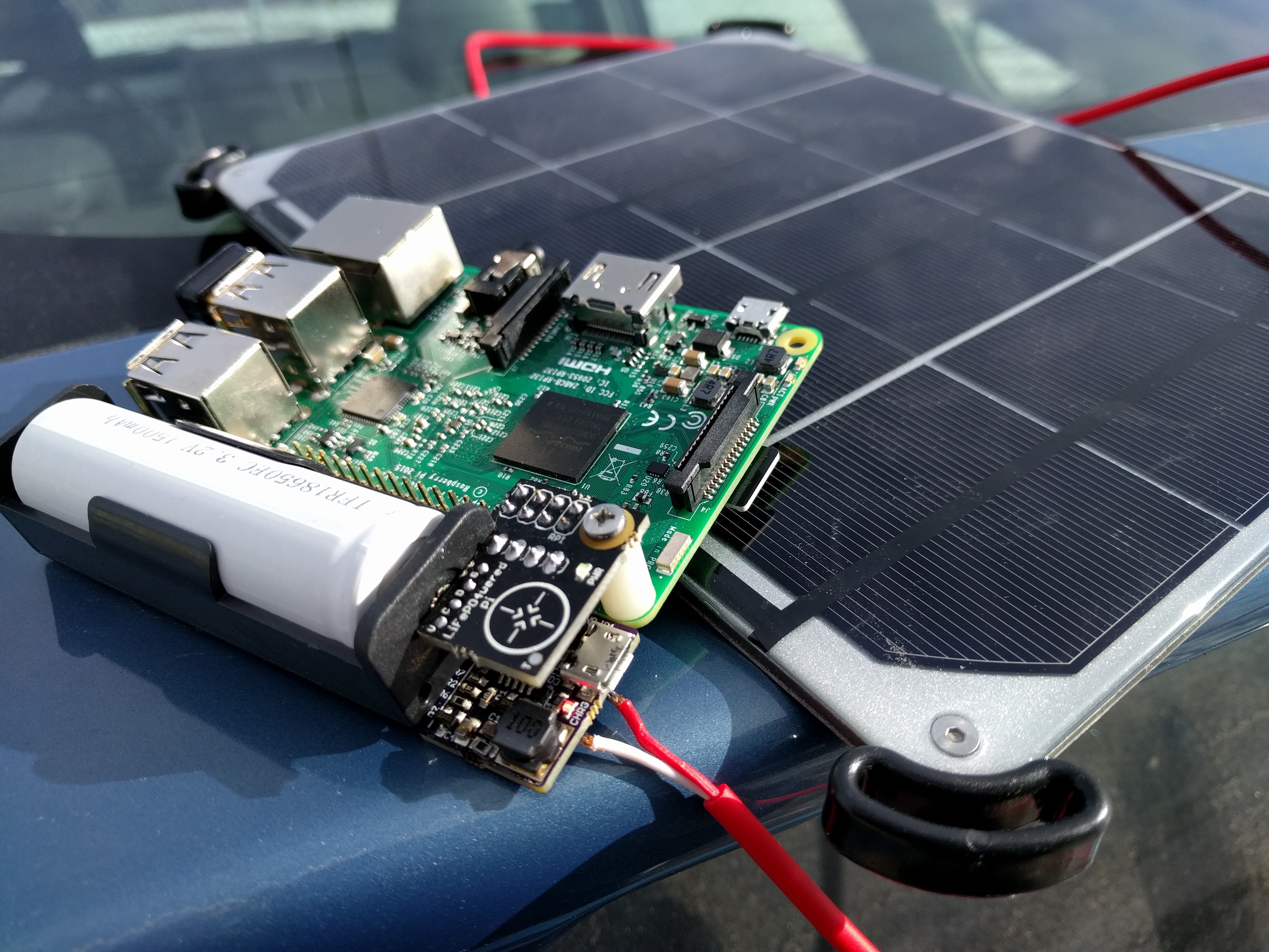
And here's the system out in the sun, charging from a 6W Voltaic Systems panel and powering a Pi 3 using the #LiFePO4wered/Pi power manager:
Hard to see the LEDs in the bright Colorado sunlight, but everything is on and charging. :)![]()
I will have to do some more testing to determine what acceptable limits on the input voltage are. The ceramic input cap loses capacity when under higher bias voltage and the peak-to-peak ripple on the charge current will get worse as well, so it will likely be less than the 16V cap rating.
-
Ready for production
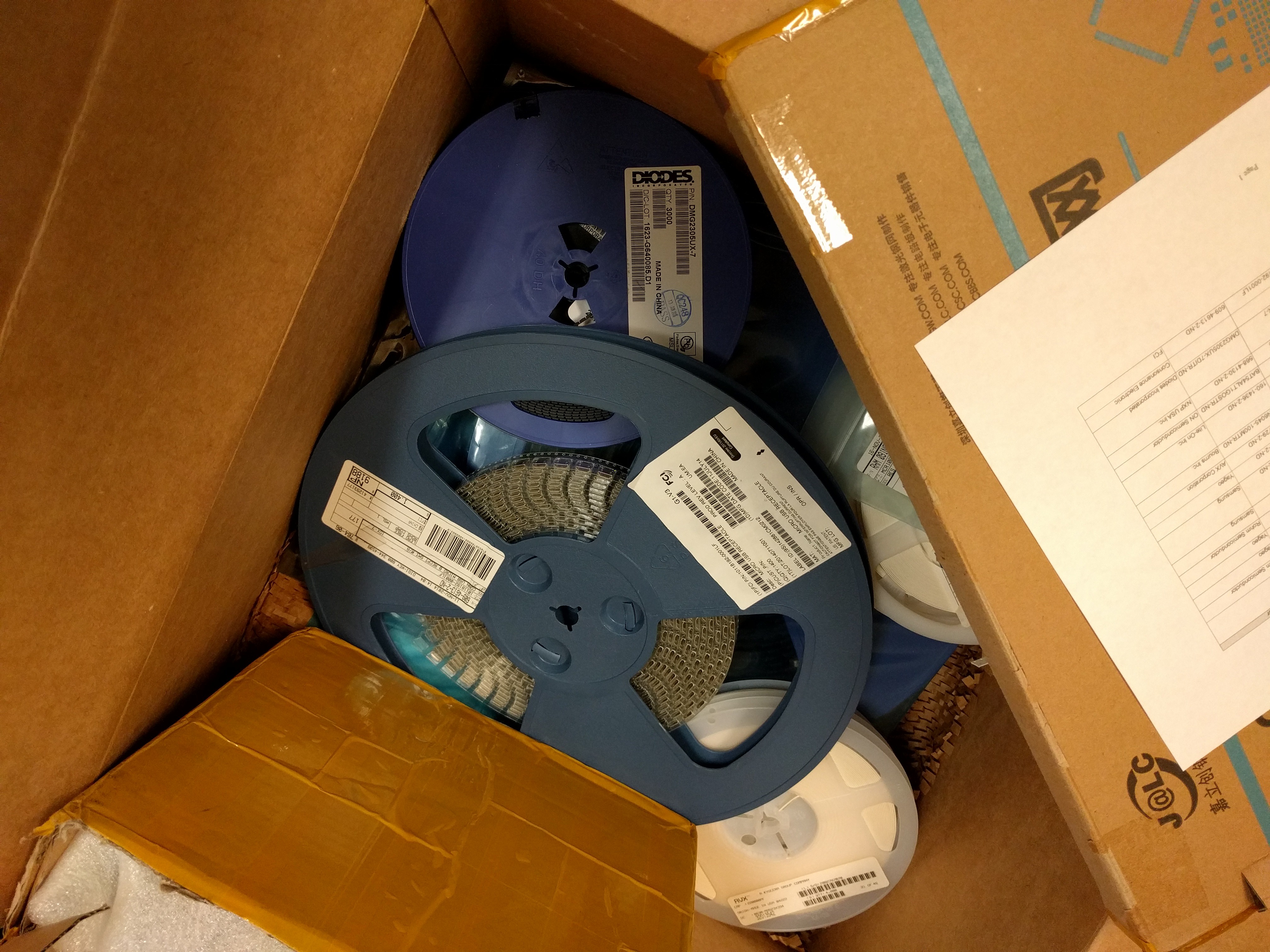
12/12/2016 at 18:44 • 0 commentsThe last reel of components I needed to start production (22uF / 16V caps) arrived from Digi-Key over the weekend, so I now have everything ready for production!
Here's the box of stuff ready to go to Colorado Tech Shop:
They will try to have my panels built by 12/14, so hopefully I can start selling by the end of the week!![]()
-
Panels have arrived!
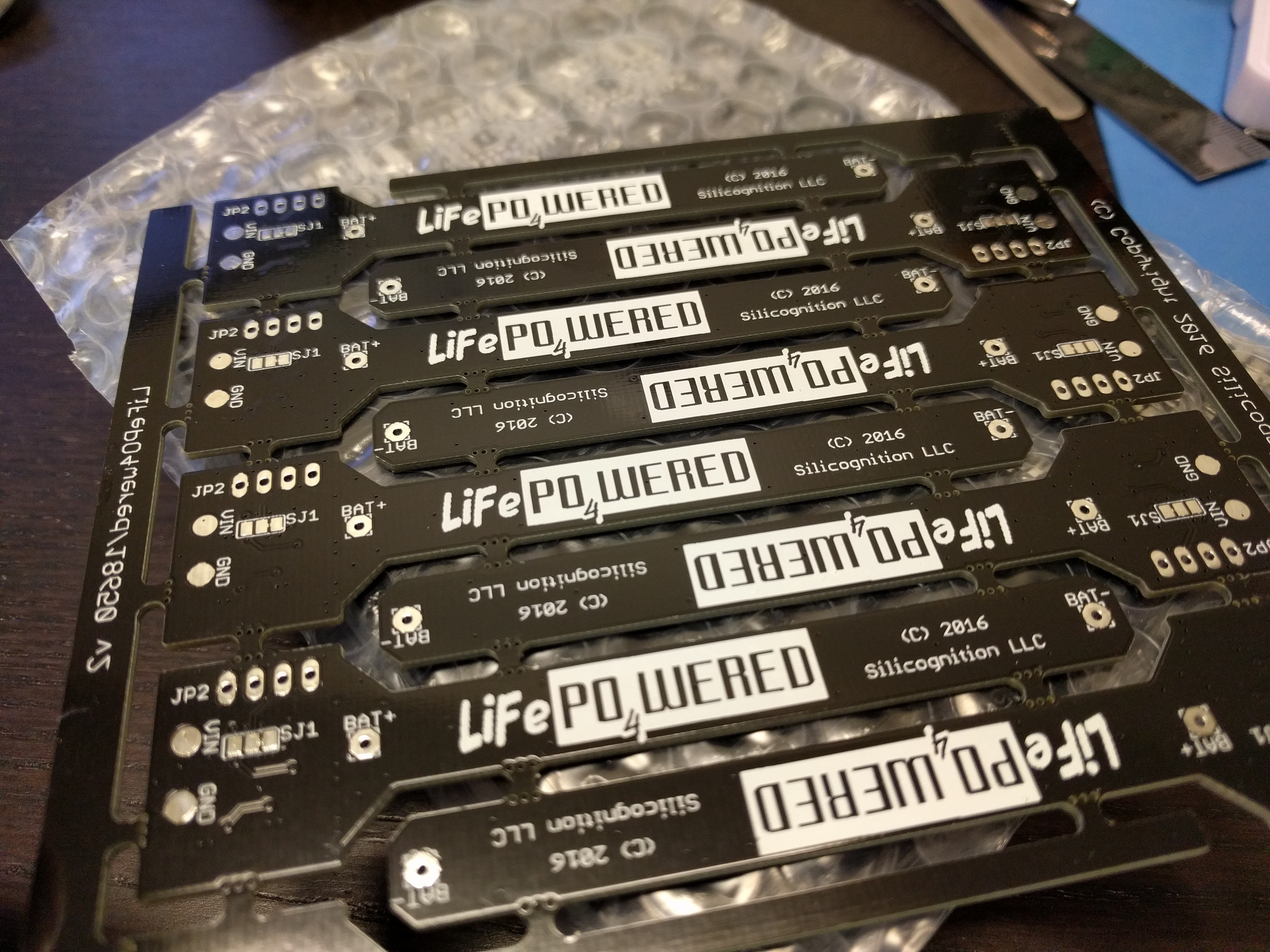
12/03/2016 at 00:29 • 0 commentsFifty panels and a framed stencil have arrived, and they look great! I have all parts in my possession, production is getting really close now. :)
![]()
-
Second prototype build
11/24/2016 at 00:45 • 3 commentsSecond prototype PCBs came in from OSH park, time for a new build! Only small changes, added a resistor, took away an optional cap to make room for the resistor, and changed the schottky diode to a smaller package.
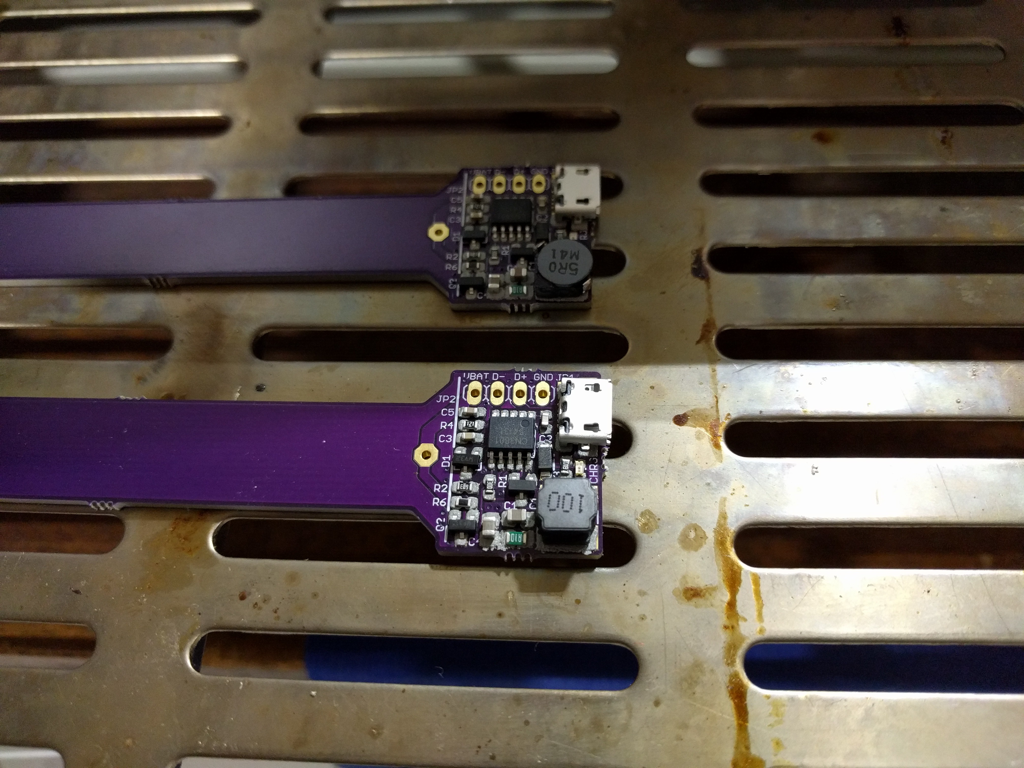
Here's before reflow:
![]()
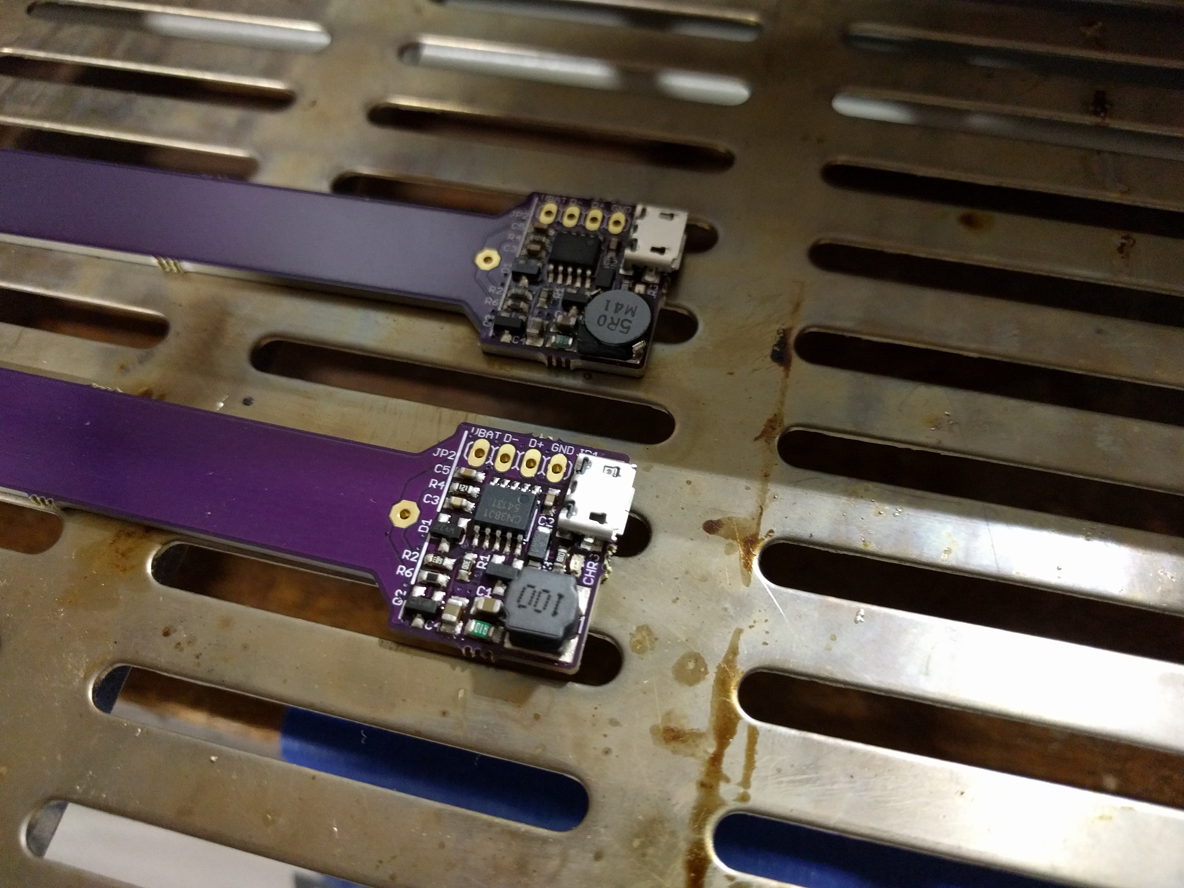
After reflow:
![]()
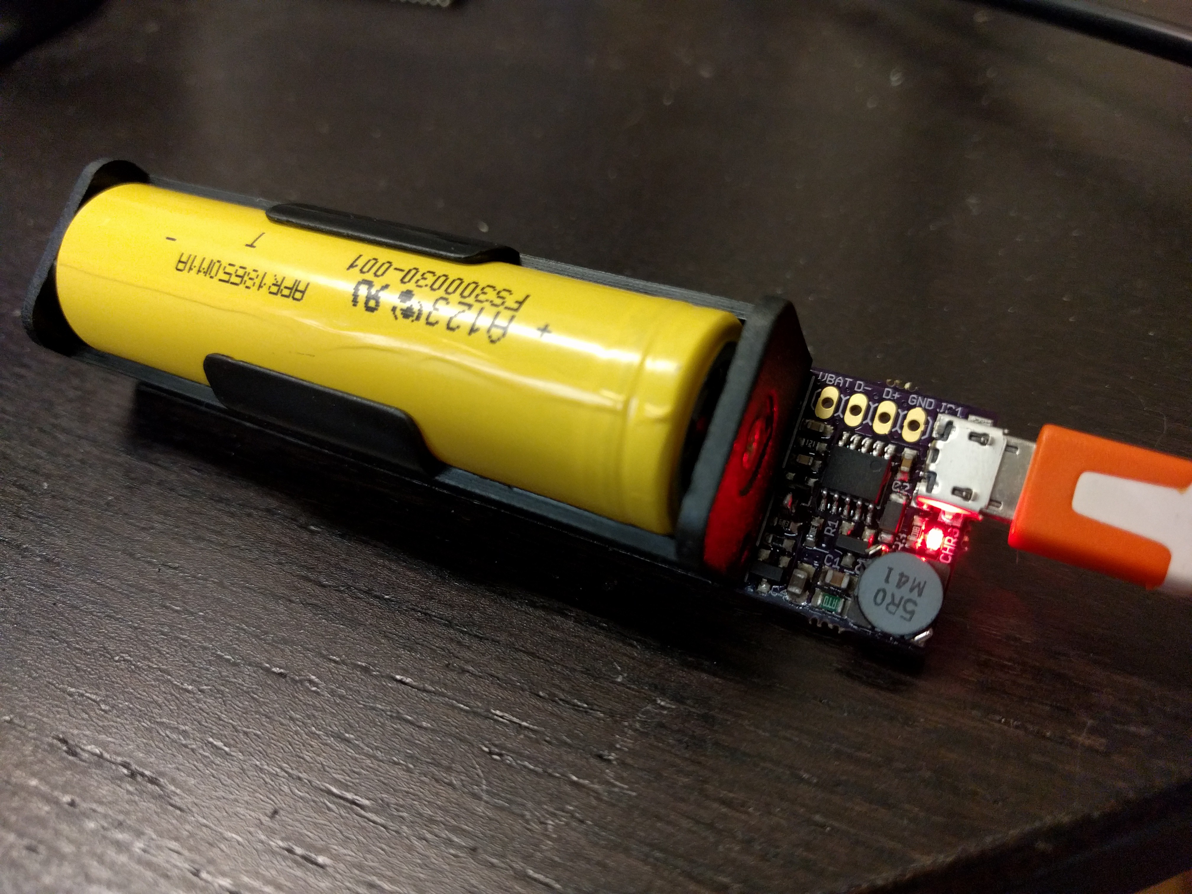
And put together with my production battery holder and battery:
![]()
Now it's time for some more testing! Putting it into a LiFePO4wered/Pi and will be running that with a Pi 3 @ 100% for some serious load testing!
Since I'm assuming this prototype will work fine (I'm an optimist, or naive, or maybe both), I also went ahead and created a panel for production:
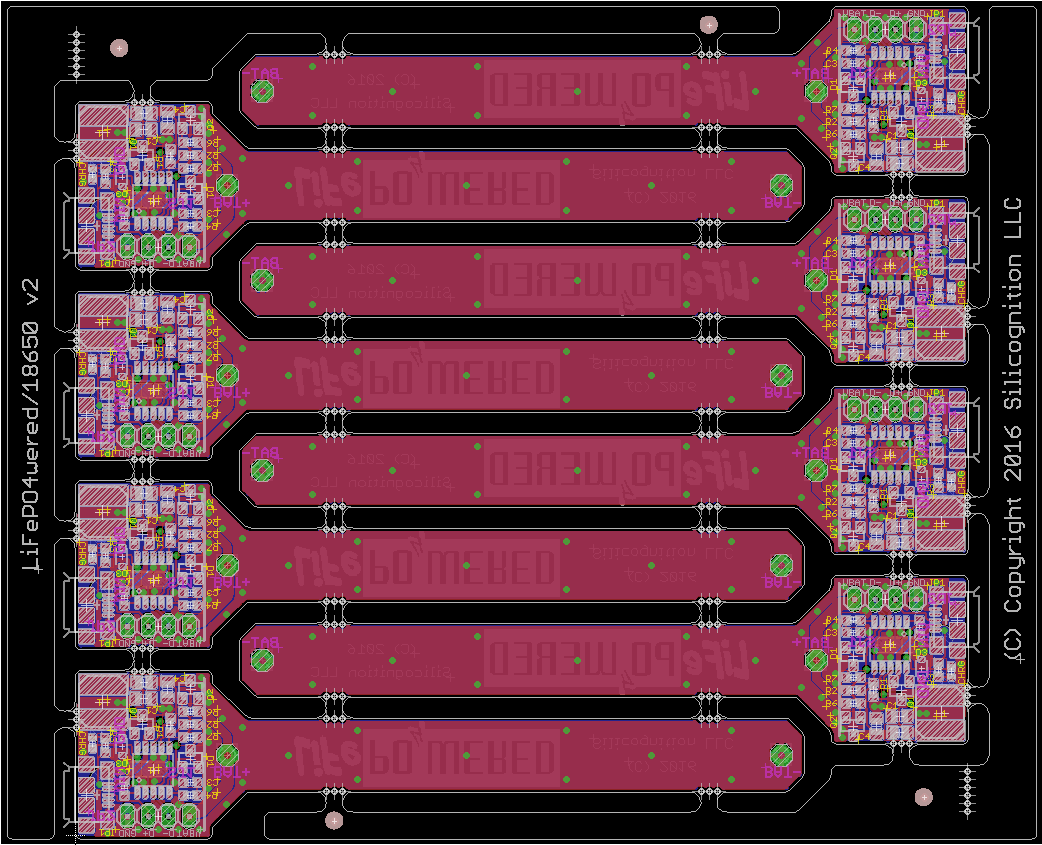
![]()
When my testing has given me enough confidence, this panel will go to the fab!
-
First test results
11/10/2016 at 18:27 • 0 commentsFirst test results are in, and they are largely positive!
I did hit a small snag at first. The LiFePO4wered/18650 would power a #LiFePO4wered/Pi / Raspberry Pi 3 just fine, but when I plugged in the USB power, it would reset the #LiFePO4wered/Pi and kill the Raspberry Pi power. Not good for something that needs to be a UPS! :-/
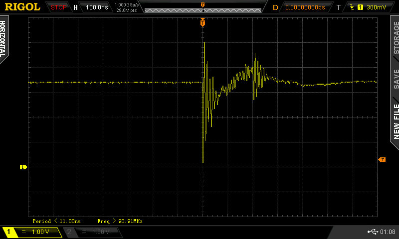
Taking a look with my 'scope, this is what I saw the battery voltage do when the USB power was plugged in:
![]()
Yikes! No wonder the micro was reset--the voltage pretty much spikes down to zero.
I traced the problem to my charger disconnect circuit. I use a MOSFET to disconnect the charger from the battery when USB power is removed, limiting battery leakage into the charging circuitry. The manufacturer indicates this leakage is about 30 uA, the MOSFET switch reduces this to 1 uA or so (take these numbers with a grain of salt, I haven't tested this thoroughly yet). What seemed to be happening is that when the USB was plugged in, the discharged 22 uF output cap of the charger would instantaneously suck the charge out of the little 4.7 uF input cap of the #LiFePO4wered/Pi. I solved the problem by adding a gate resistor to the MOSFET which, in combination with the gate capacitance, would delay turning on of the MOSFET enough for the output capacitor to get charged first. No more resets! :)
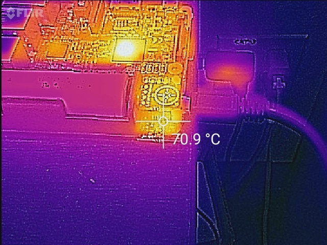
I wanted to know if the new charger would keep up with the worst case scenario for the current #LiFePO4wered/Pi: charging a near-empty cell with high load on a Pi 3. The current charger can't do it, it's limited to 480 mA charge current and thermal limiting problems are the worst when the battery voltage is low. I threw the worst case at it: A Pi 3 with all 4 CPU cores at 100%, Ethernet connected, the Raspberry Pi CPU at >100 degrees C and battery nearly dead. Here's a thermal image of the torture setup:
![]()
I'm very happy to say that the LiFePO4wered/18650 prototype passed with flying colors! :) The heat production stayed reasonable, the system was stable through the night and the battery was charged in less than 6.5 hours (didn't check often enough to see when it was actually done)!
Very positive indeed. I've started work on the next prototype, hopefully the last one before making a production panel.
-
First prototype build
11/09/2016 at 18:10 • 0 commentsAlways a good day when you get a package from OSH Park. :)
![]()
As you can see, I went fancy with the silkscreen this time. I have to say I like it a lot, looks much more "branded" now compared to the simple vector font.
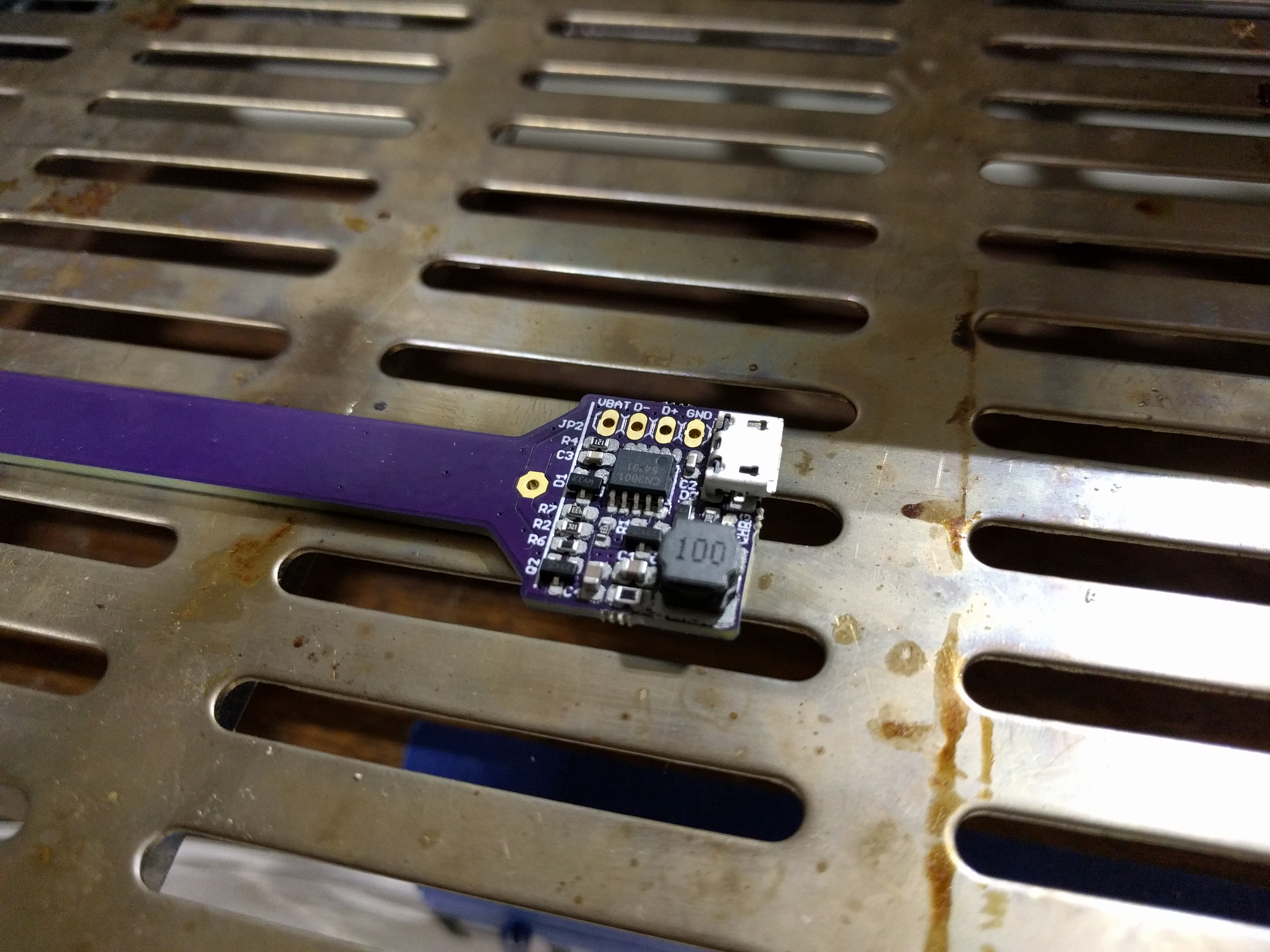
Cut a plastic film stencil on the Tinkermill lasercutter, this worked fine since there aren't any tiny pitch components. I placed the parts by hand, here's a picture of two proto's ready to be reflowed:
![]()
And after reflow. Looking good!
![]()
As you can see I used a different inductor on the two prototypes. I'm making some variations to see what works better.
Here's a picture of the completely built-up unit with 18650 LiFePO4 cell:
![]()
And a prototype used with the #LiFePO4wered/Pi:
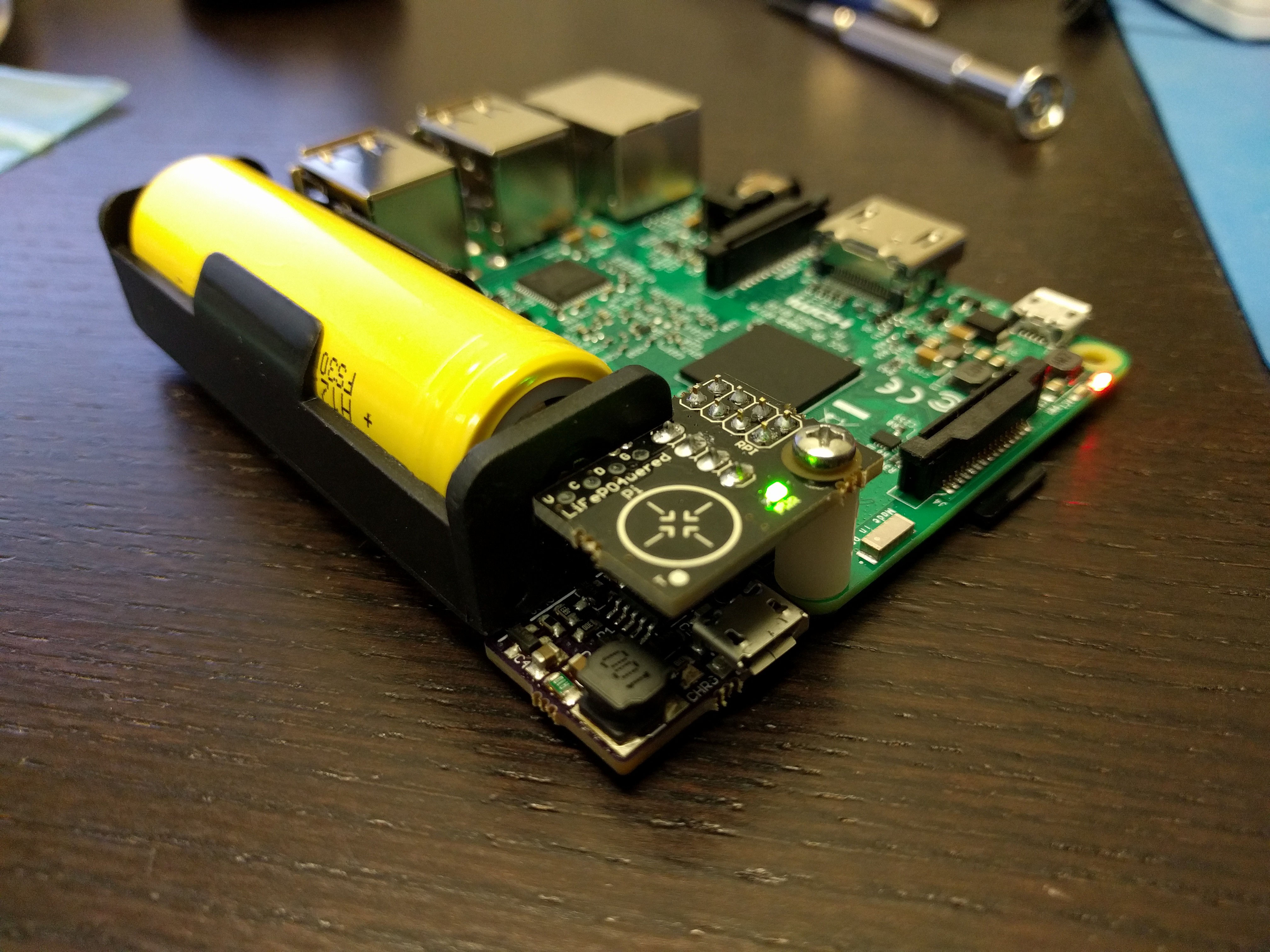
![]()
Now it's time for testing, first impression is good--as you can see, the Pi is running. :)
LiFePO4wered/18650
LiFePO4 battery technology, made easy for makers - a bigger version
 Patrick Van Oosterwijck