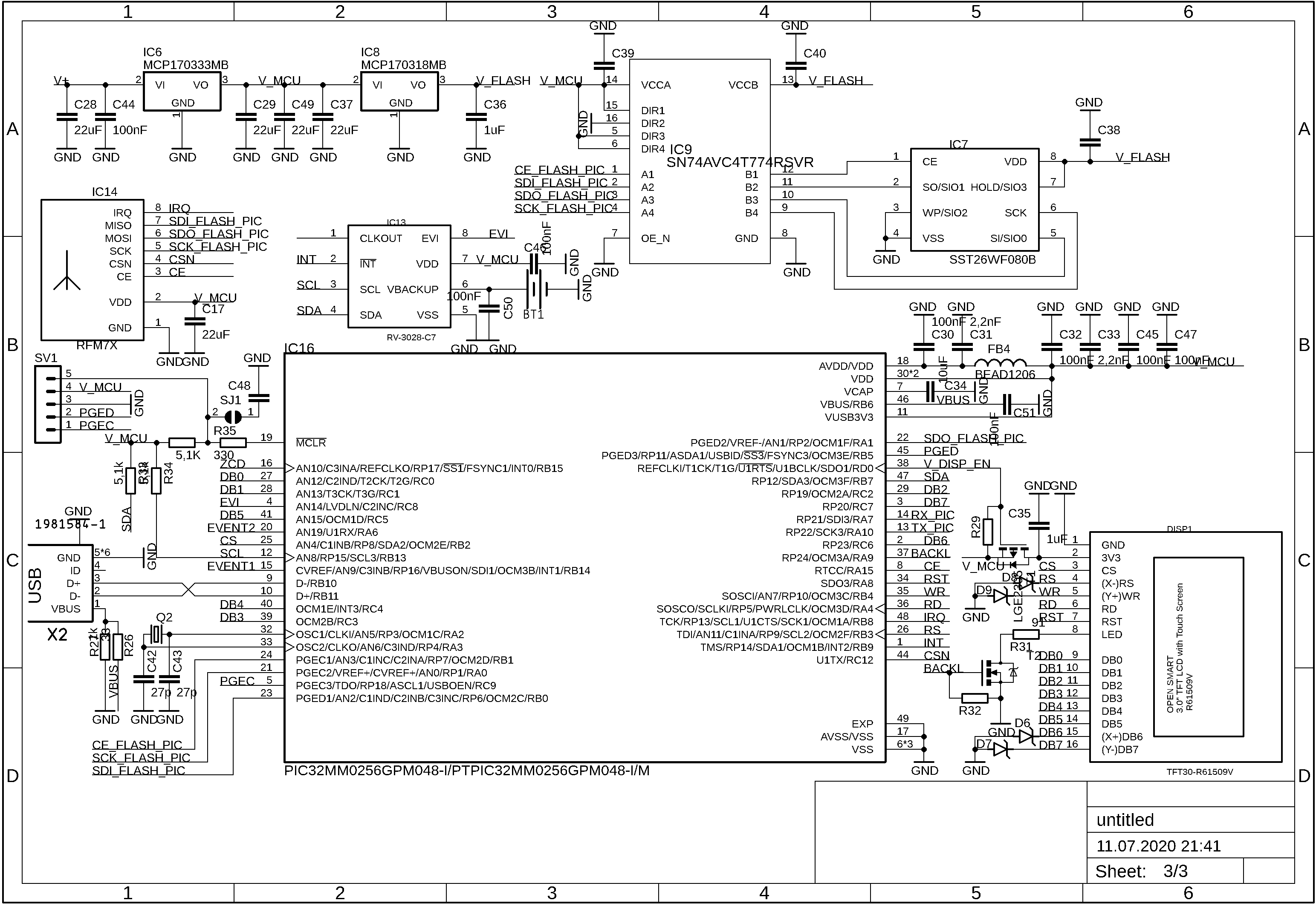
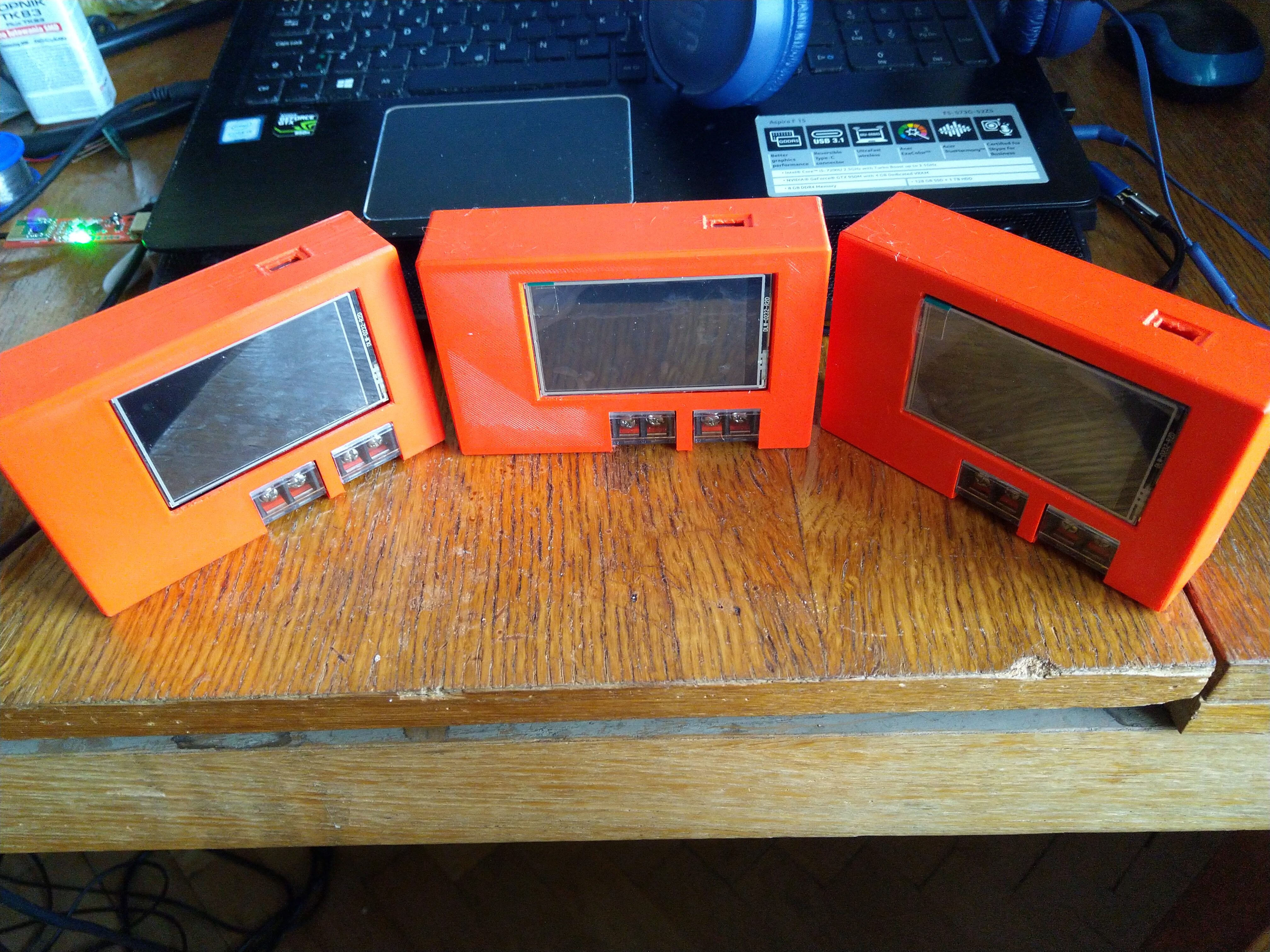
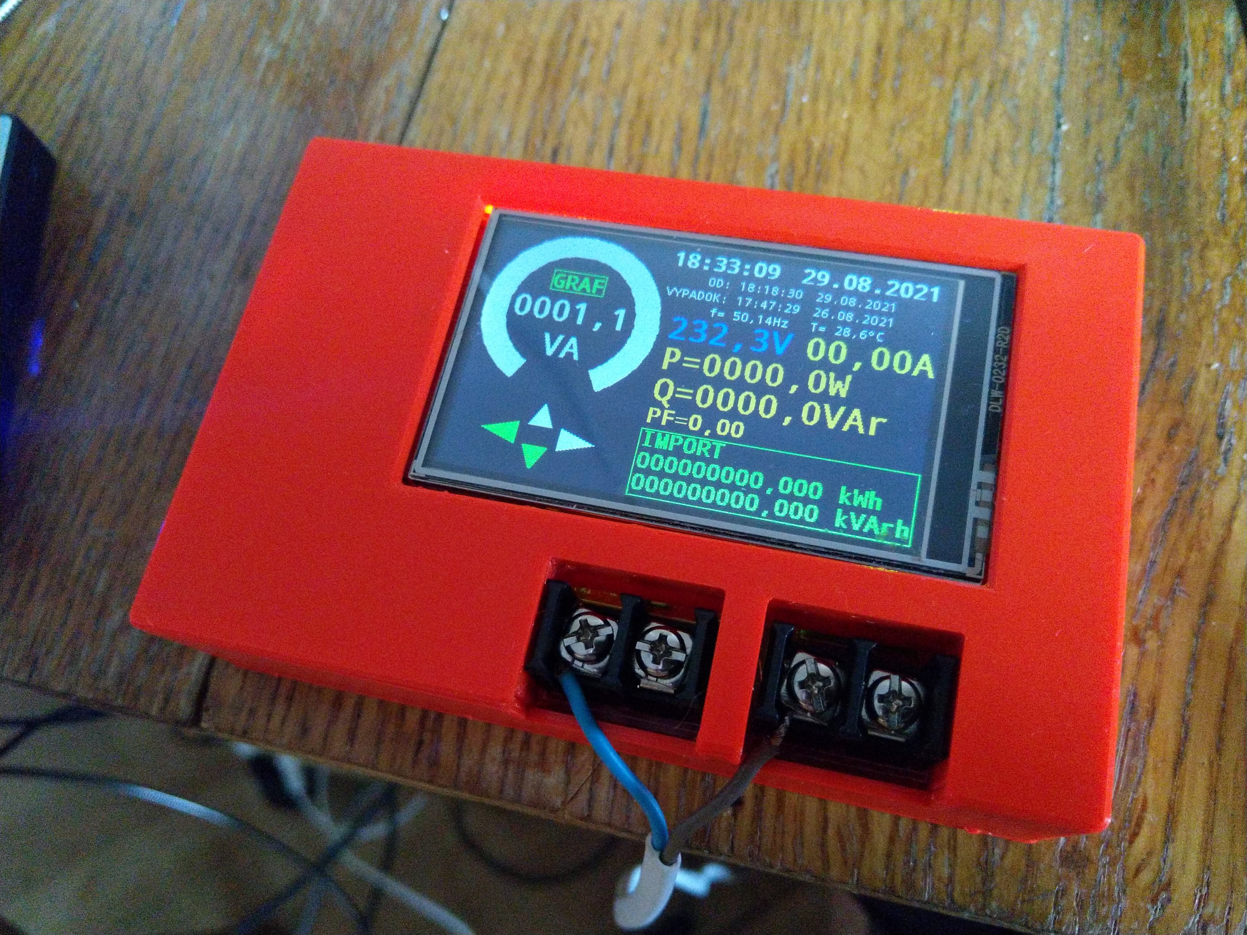
Measured values are presented in both numerical and graphical formats. The user can switch between screens by tapping on the left or right side of the touchscreen. Additionally, the display shows the current time, power-up timestamp, and the last blackout timestamp. I chose the RV-3028C as the real-time clock (RTC), and it functions exceptionally well.
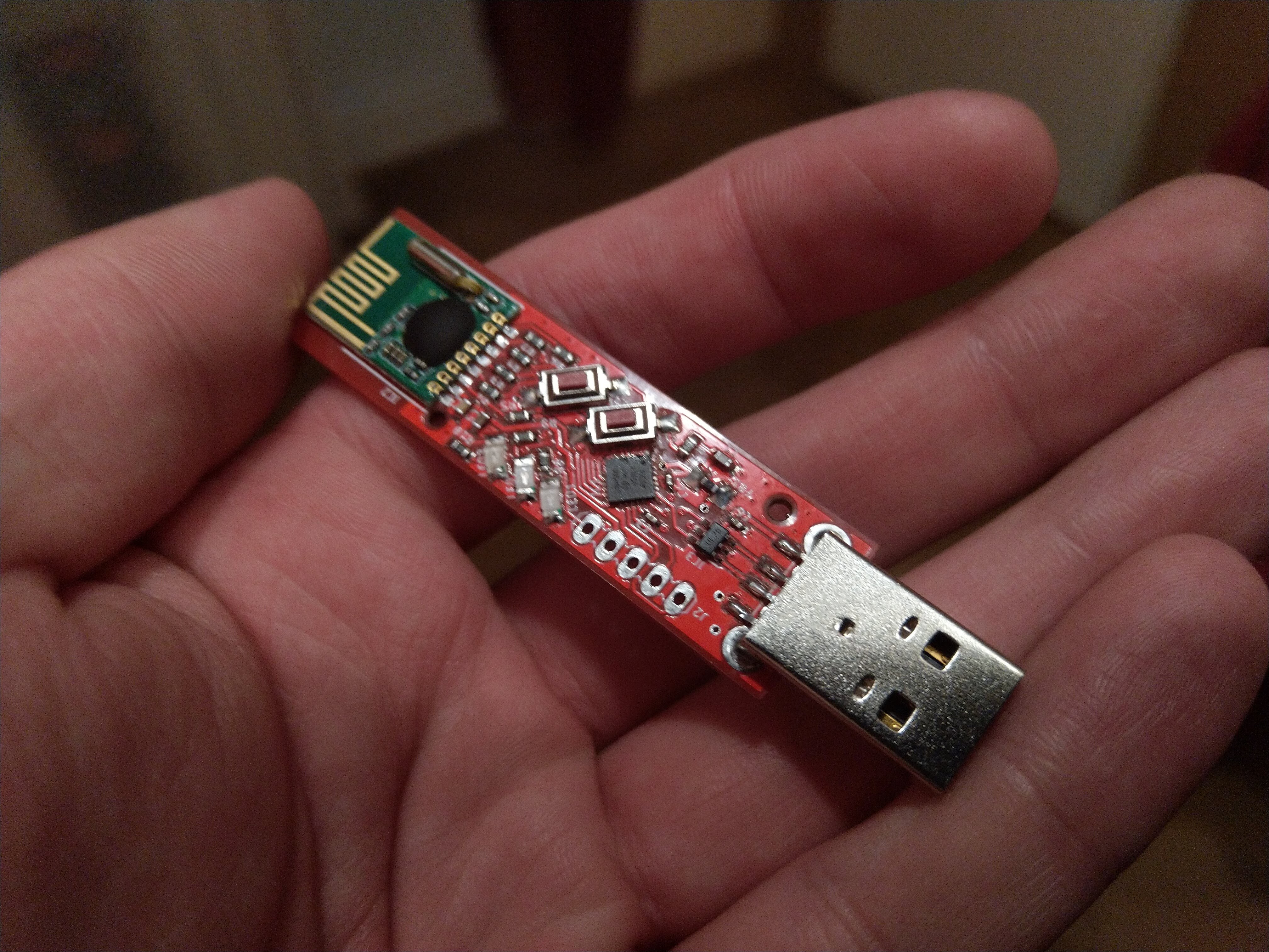
All measurements are recorded in the SPI FLASH memory SST26WF080B, which can store up to 16384 logs. The default logging interval is 5 minutes, but it can be adjusted within a range of 10 seconds to 20 minutes. Users can access measurement data and adjust the energy meter's settings in two ways: either via USB or remotely through the RFM75 RF transceiver, which requires a USB dongle on the PC side. Both the energy meter and the USB dongle enumerate as virtual COM ports, allowing the use of any serial terminal software.
I have created a simple Command Line Interface (CLI) that supports the following commands:
--DT<hhmmddmmyy> - set time and date
--READ<> - Read current measurement
--ENER<> - Read all energy accumulators (temporary and total)
--LOGS<> - Read all logs from external flash memory
--LPER<ssss> - Set the logging interval (in seconds)
--?LPER<> - Read the logging interval
--DISP <n>- change screen (n: 0-primary display, 1-apparent power plot, 2-active power plot, 3-reactive power plot, 4-current plot, 5-voltage plot, 6-info screen)
--RFCH<ccc> - set RF channel (000-127)
--AD<aaaaaaaaaa> - set 5-byte address for the RF communication (HEX)
--ID<max. 20chars> - set custom identifier (name)
--RAMLOG<> - read last 256 samples (V,I,P,Q,PF...)
--RESET<> - reset the energy meter
All commands are terminated with a carriage return and line feed (CR LF).
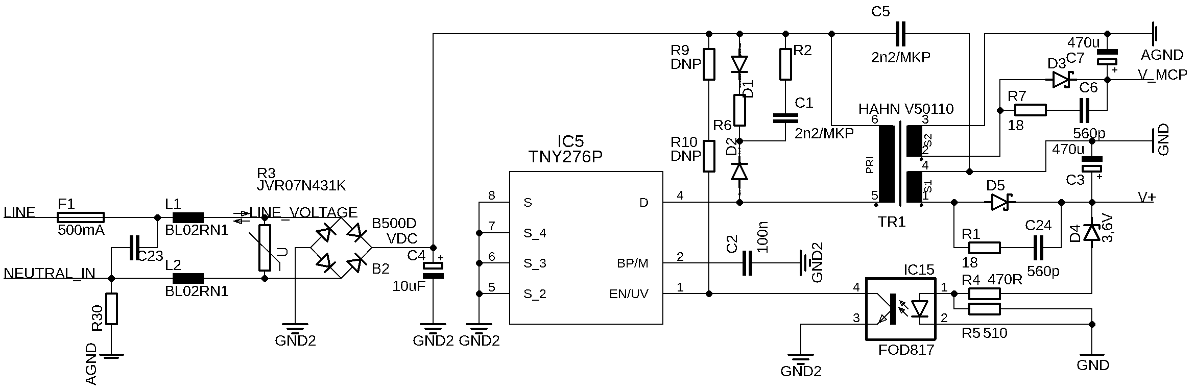
The energy meter is powered by a simple isolated flyback AC/DC converter based on Power Integrations' TNY276. The flyback transformer features two isolated windings: the first powers the measuring circuits, while the second powers the microcontroller (MCU), display, and communication interfaces.
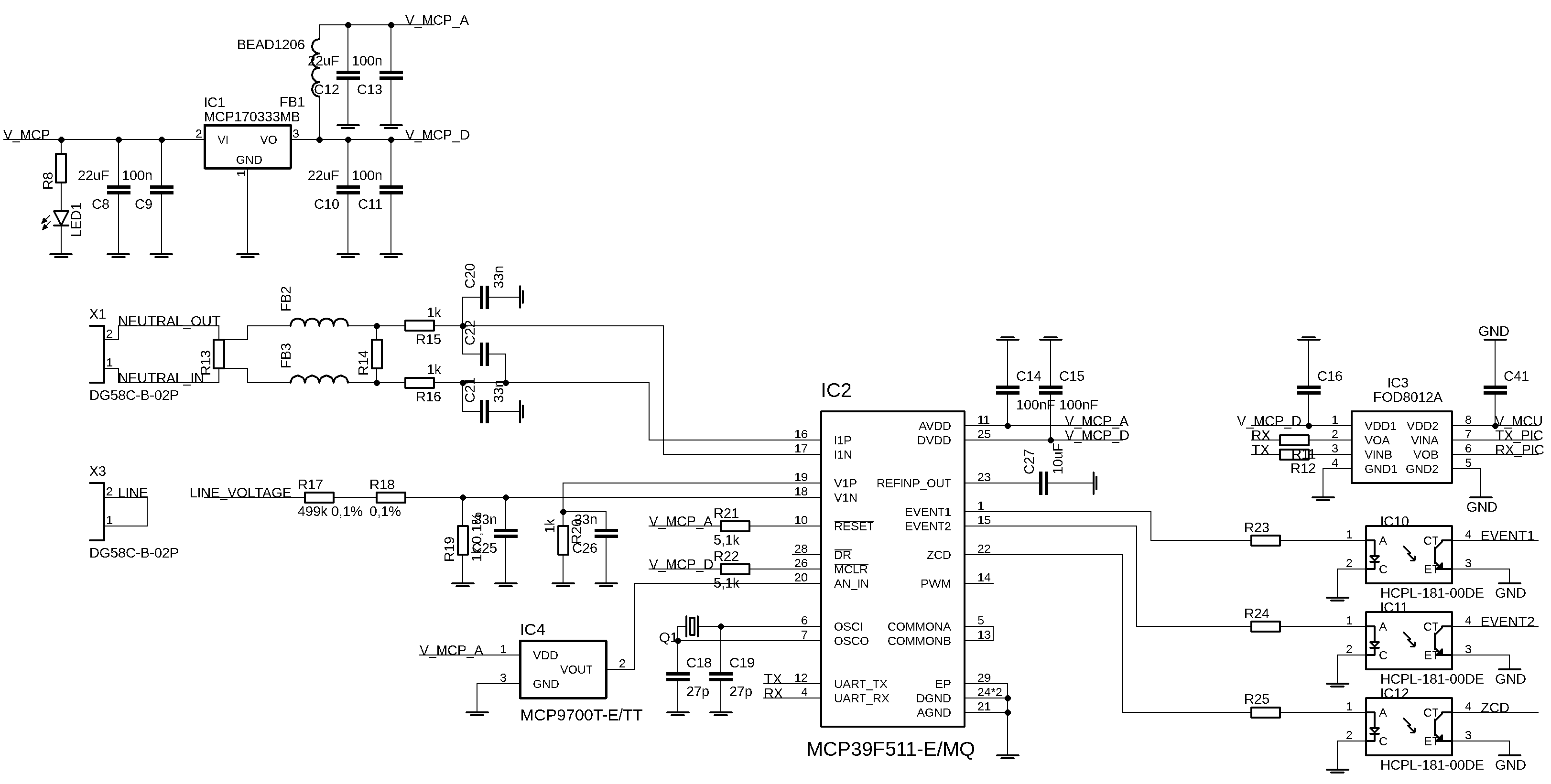
An isolation barrier between the microcontroller and the measurement circuit is provided by the optocouplers FOD8012 and HCPL-181.

Did you use some library to create the graph visible on the LCD in the video? In general, the GUI on the LCD is pretty impressive.
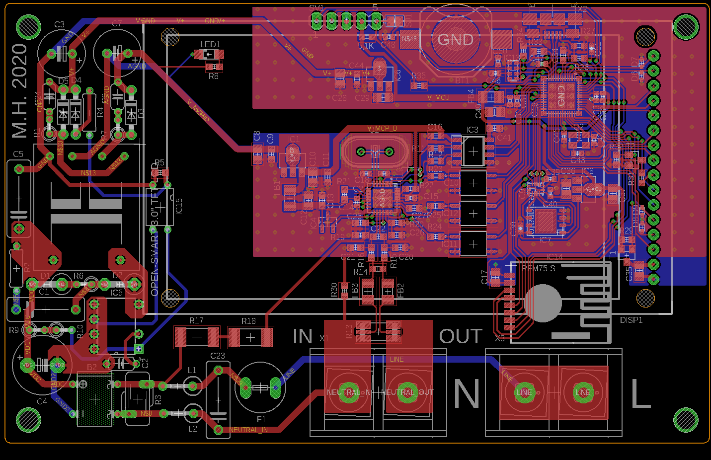
I think the main cables are way too close to the LCD (it looks like LCD is touchable, based on the video). I’d be worried that if the connector's screw gets loose, the cable fall off and touch && shock me. Could maybe change printed enclosure a bit to avoid that.