-
1Lithium Battery Pack build
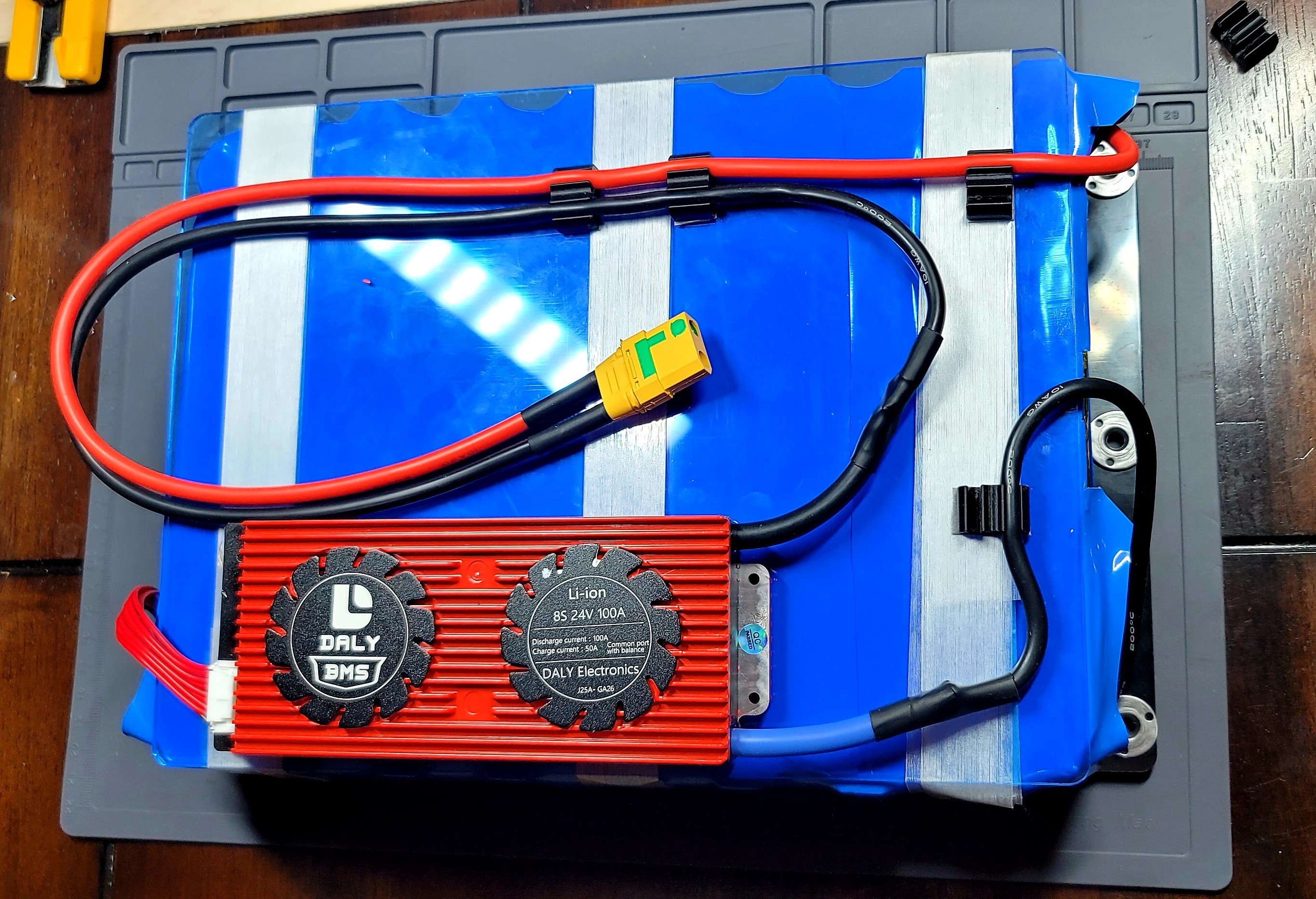
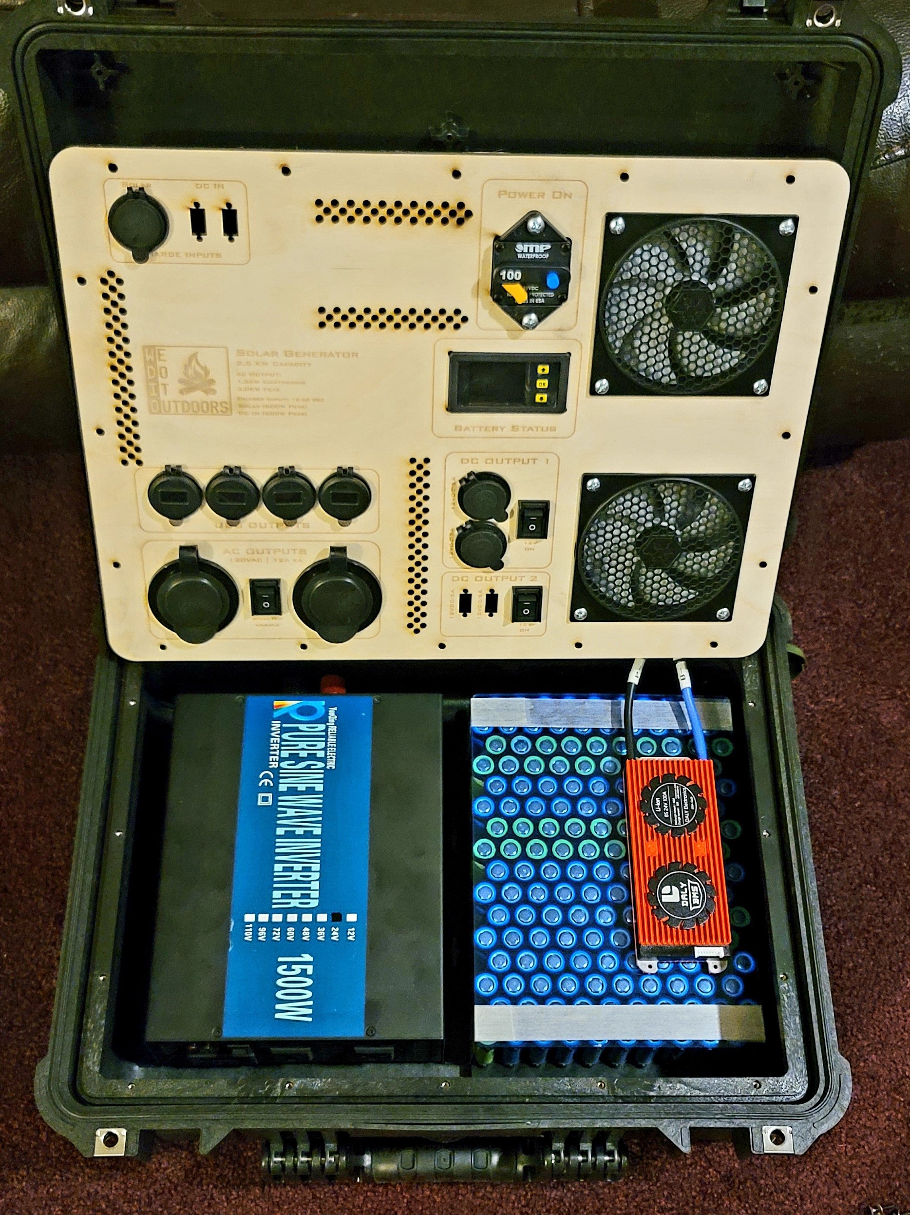
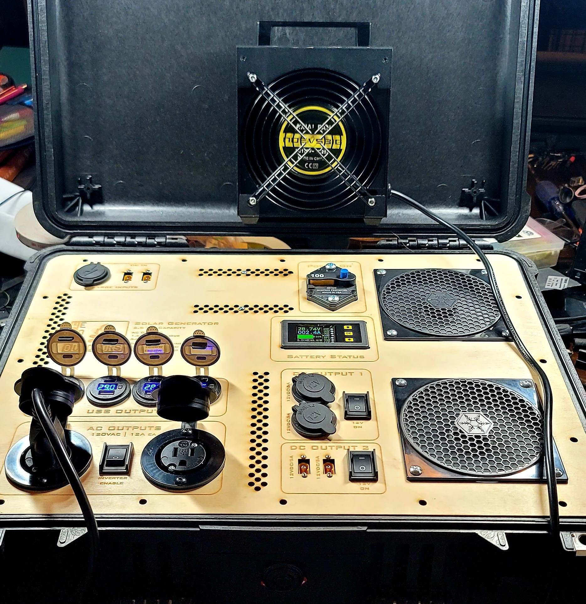
Before starting a pack build yourself I would highly recommend you finish all of your ongoing projects that you can, because this will take a huge percentage of your focus. First a finished pack photo because I know many of you won't read to the end:
![]()
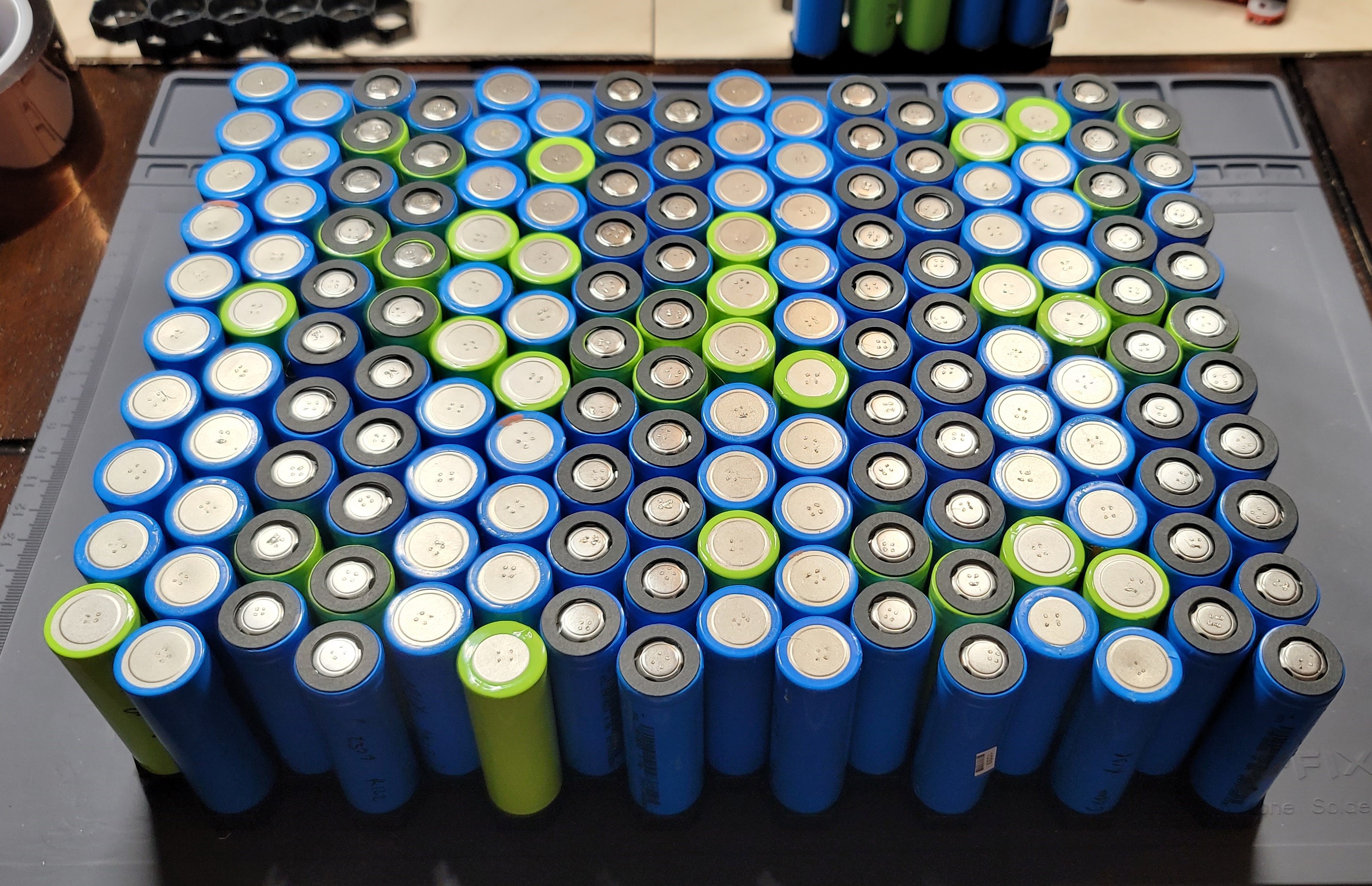
I sourced my cells from used modem batteries for the prototype (From Battery Hookup), at $0.40 per cell for 2200mAh cells it was an economical way to test the platform and work my way up to the full 2.5kW pack with custom electronics. Most of the cells I salvaged came in at 2000-2100mAh so the prototype pack is around 1.7kW currently. Any cell that tested below 2000mAh was put to the side for future projects. If you aren't in a mad dash to build one of these I would keep an eye out on the following websites for a good deal on new cells. The time it takes to separate the modem batteries, charge each cell, and test each cell adds up very quickly; While I love the idea of repurposing used laptop or modem batteries, getting your hand on used cells can be expensive with groups catching on to their use. I had a few companies offer to let me buy used laptop batteries by the pound, others charge you per cell.
Battery Hookup: https://batteryhookup.com/
Power to Spare: https://www.power2spare.net/
For the next pack I am planning to jump back up to 8S 30P with cells testing ~3000mAh, which will bring the pack to 2.5-2.6 kW.
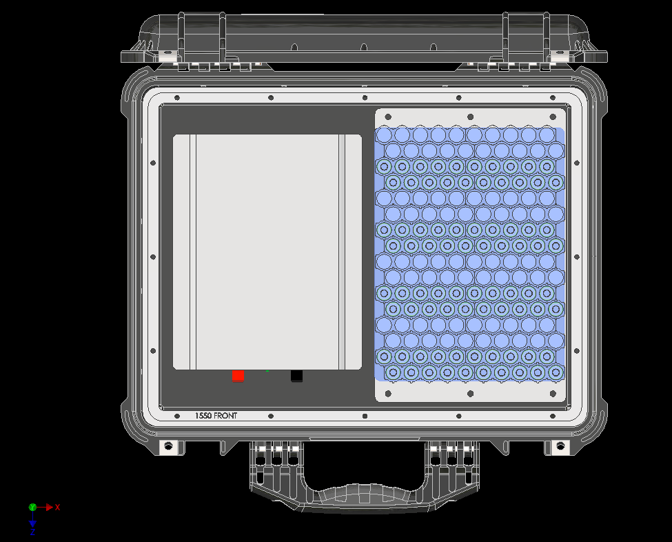
First step was to design the battery pack in CAD using a Pellican 1550 case model to ensure it would fit alongside the 1500W Inverter:
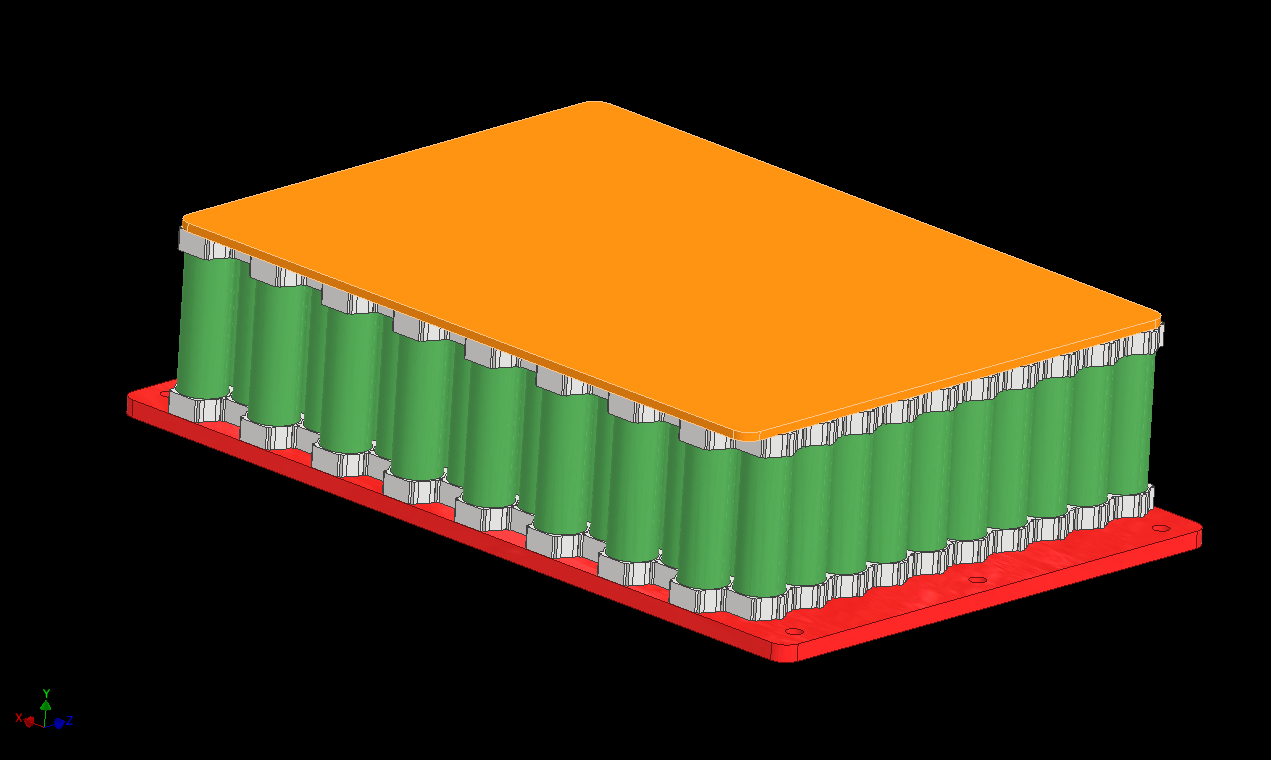
The pack is a fairly straightforward construction using honeycomb cell holders and 2P nickel strips (more on that below). I was not content with using something like VHB tape to mount the pack to the pelican case, or wedging it in since this pack will live in either the back of my Jeep or in my overlanding trailer on trips; and is going to get a bit jostled around. I decided instead to laser cut a top cover and bottom base, then attached them to the pack with fiberglass reinforced strapping tape.
If you fall down the 18650 pack building rabbit hole on Youtube you'll get varying opinions on spot welders. There are plenty of options out there but I opted for a lithium powered miniature spot welder (See Details section).
Here is a photo of the pack with the top/bottom plates. The bottom plate is ABS and designed to accept 1/4-20 Barrel nuts for mounting to the Pelican case.![]()
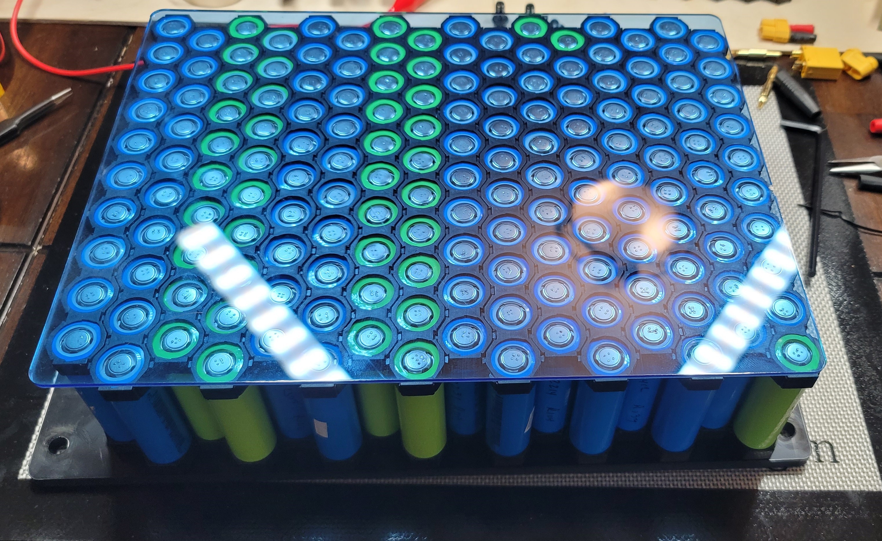
The next step is to orient each series cell in the pack to prepare it for spot welding. I added an additional paper isolator ring to each positive terminal just as a precaution.
![]()
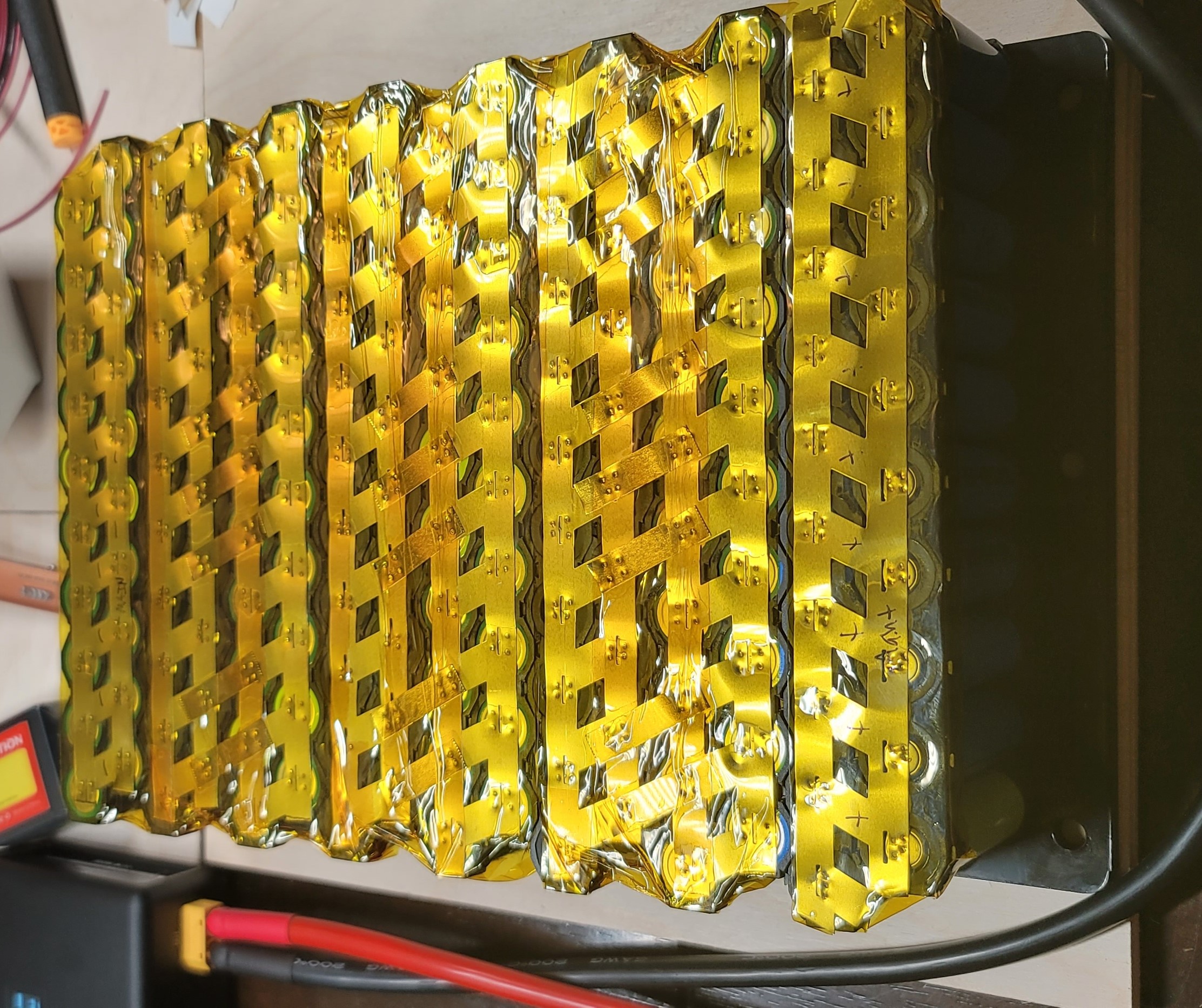
The observant among you may have noticed that the pack shown above is an 8S pack. After spot welding the pack together I discovered that while the USB chargers I used can handle up to 30V; A fully charged 8S pack at 33.6V is too high for them to operate. So I carefully dissected 1 series pack turning this into a 7S pack. I plan to switch back to an 8S pack for Gen2. A Peak under the shrinkwrap:
![]()
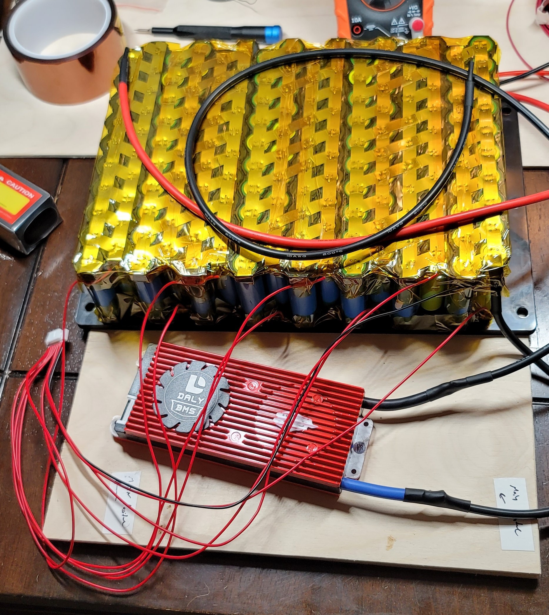
Adding a BMS was simple, I left a tab on each positive nickel strip for soldering:
![]()
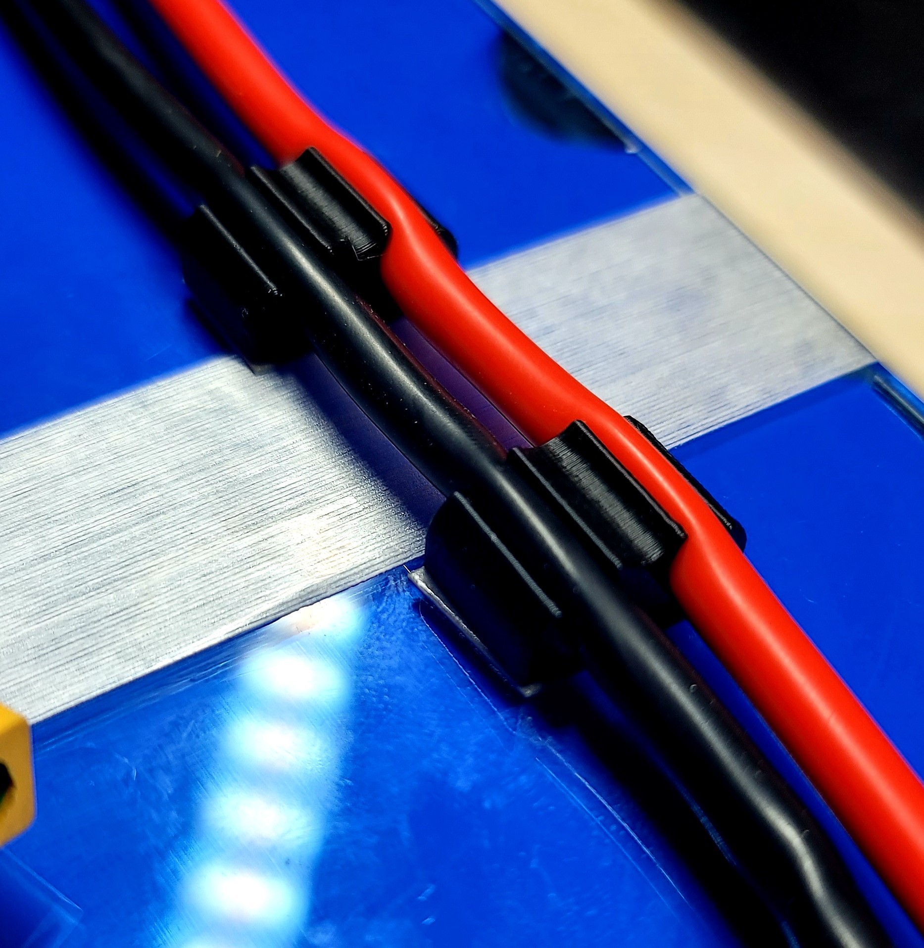
I must have ordered 5 different diameters of heat shrink wrap until I found the right diameter, I need to measure it again and will make sure to put the right size into the BOM. Some simple 3D printed wire clips were made and VHB taped to the acrylic top cover:
![]()
I'll add some files for the 3D printed and laser cut parts shown on this step.
-
2Mounting and Wiring
Now that the prototype battery is complete it was time to mount the first layer of parts into the Pelican case. The 1500W continuous inverter was paired with the 7S 30P pack as they both fit snugly into the bottom of the pelican case. The Inverter required 4 holes to be drilled through the bottom of the case, and the Battery pack needed 6. These holes were sealed using a laser cut gasket and washer. I've been playing around with FIP gaskets for a few of my engineering clients with good success, I may add some FIP gaskets directly to the case for the next prototype.
![]()
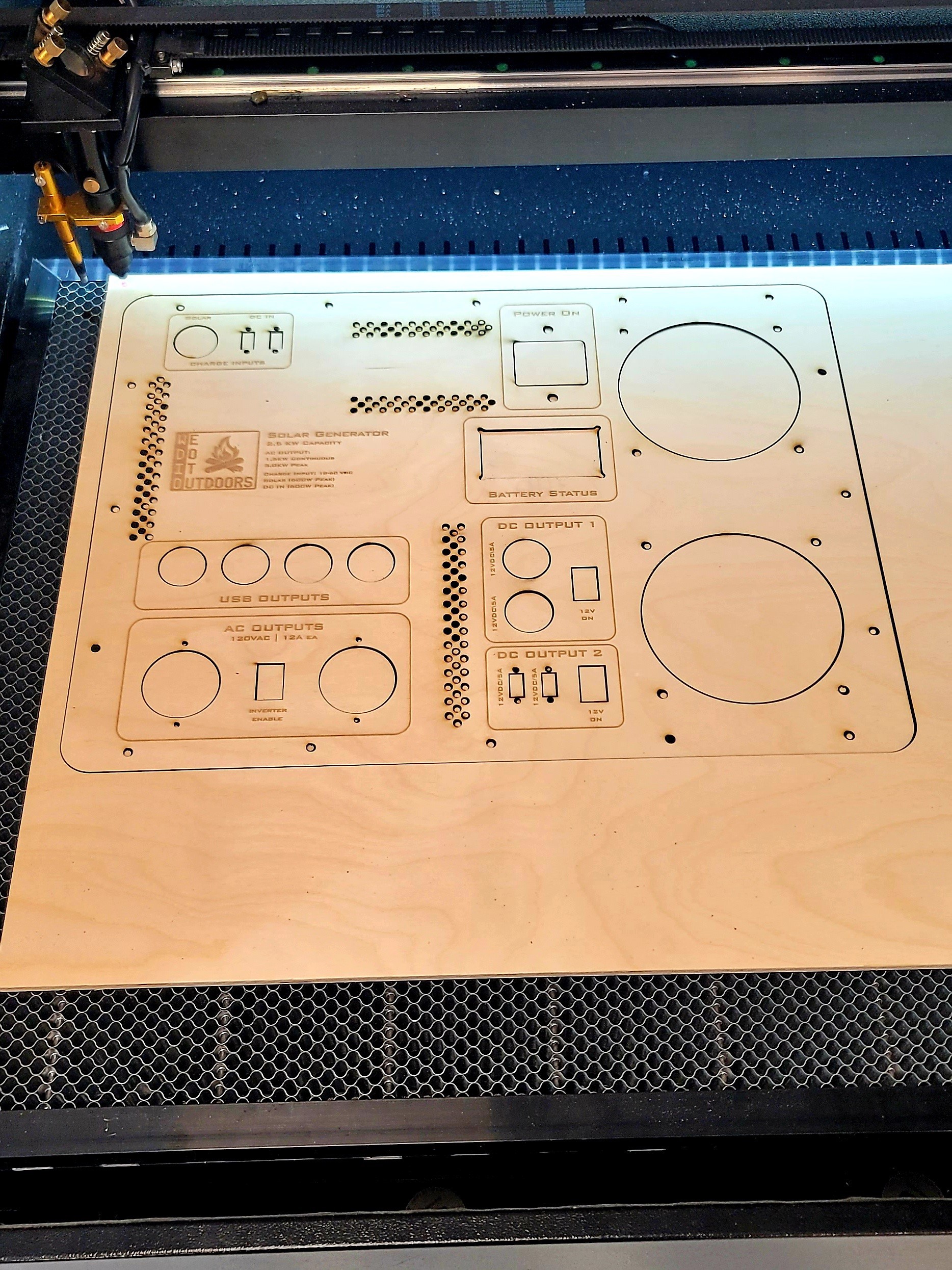
The faceplate was laser cut from 0.25"-ish thick birch plywood. Once I get the design down for the custom PCBs I plan to laser cut the faceplate from 0.19" thick 6061-T6.
![]()
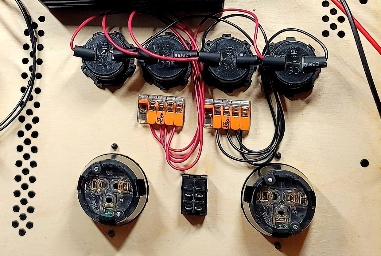
The wiring is... well... not going to win any awards. I employed one of my favorite techniques for making branched connections that can be repaired in the field. A small strip of VHB double sided tape on the back of a Wago snap acting terminal block makes for simple solder-less connections:
![]()
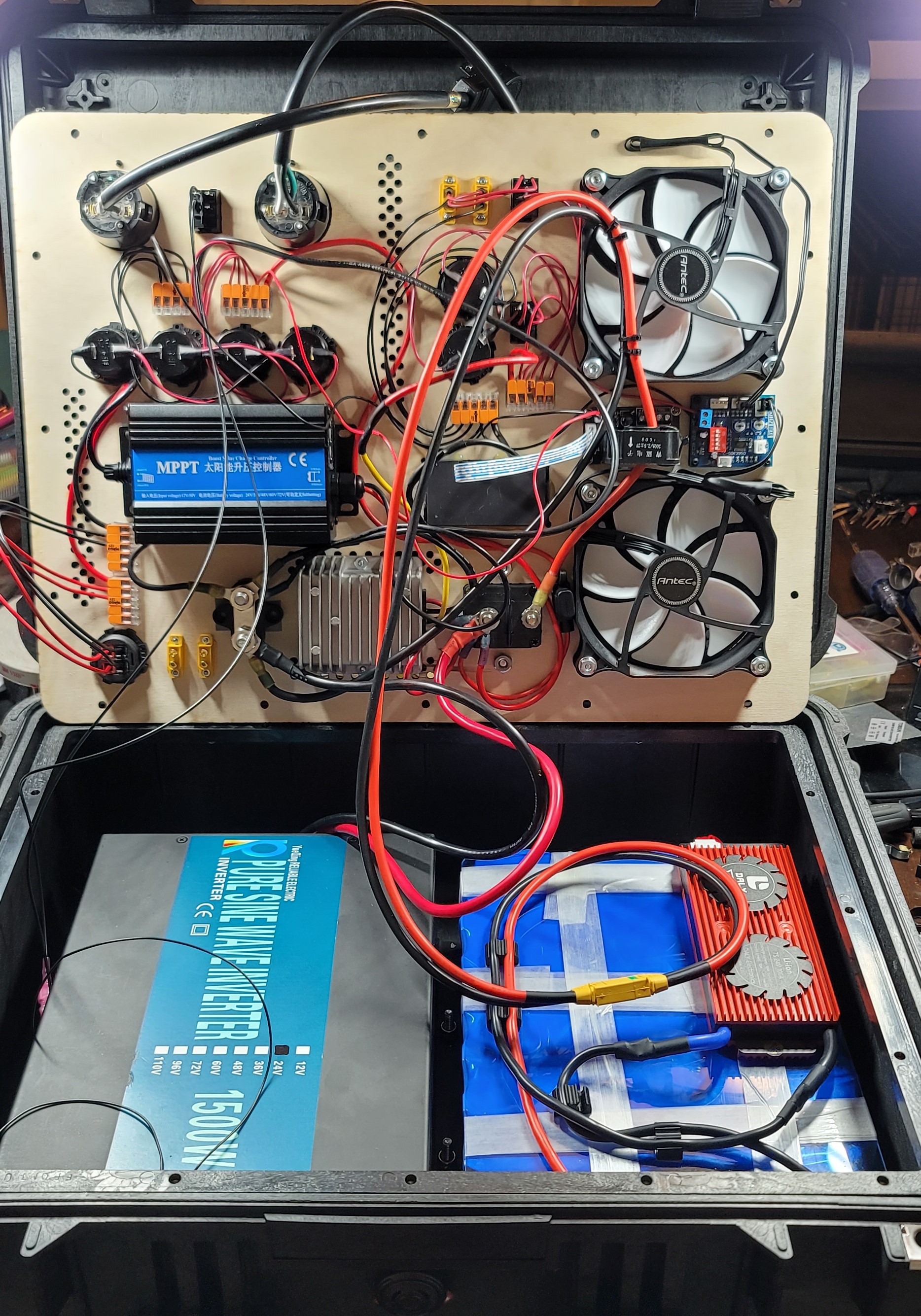
Pre "Zip Tie Mania" wiring mess:
![]()
Once it's all closed up it looks much better of course:
![]()
Rugged Solar Generator 2.5kW
A 2.5kW solar generator designed for overlanding and outdoor adventures in mind.
 Philip Ian Haasnoot
Discussions
Become a Hackaday.io Member
Create an account to leave a comment. Already have an account? Log In.