Design/ Schematic
After dismantling the remote, I found that a momentary push button was responsible for generating the RF signal that either turns the lights on or off. To control this remotely, I simply wired the output of an optocoupler (4-pin PC817) to the input and output terminals of the push button, and the input of the optocoupler to a GPIO pin on the ESP8266 (GPIO4 or D2 on the NodeMCU dev board). I also wired the Reset pin on the ESP8266 to GPIO16 (D0) so that I could periodically sleep and wake the unit from deep sleep mode in order to save energy.
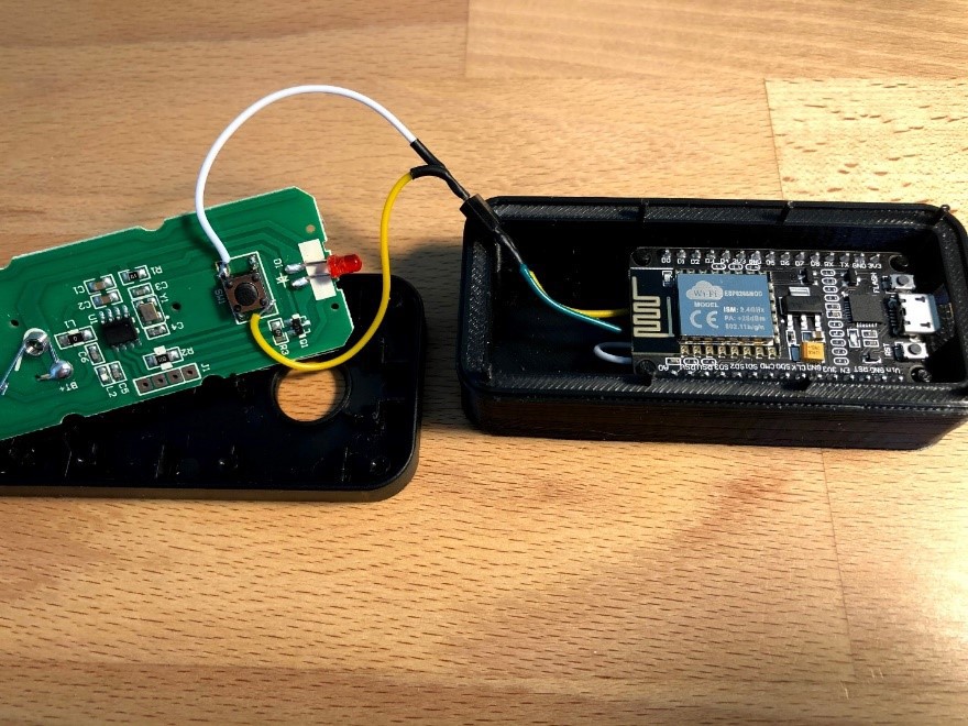

Code
The firmware code burned onto the ESP8266 consisted of the following main steps:
- Connect to local WiFi network
- Get current time from NTP client (north-america.pool.ntp.org)
- Get sunset time from API call and deserialize JSON return (http://api.sunrise-sunset.org/json?lat=LAT&lng=LON&date=today)
- Convert time values to integer representing minutes from midnight
- If current time is within 40 minutes before sunset, trigger RF remote (turn lights on) and keep lights on for 2 hours
- Both values (40 minutes prior to sunset and 2 hour duration) are hard-coded, but can be adjusted if needed
- After lights turn on, run delay function for 2 hours before triggering RF remote (turn lights off)
- Enter into deep sleep mode for 10 minutes (drops current draw and saves power)
Throughout the day, the unit gets the current time value from the NTP client every 10 minutes and compares this value to the local sunset time. As long as the current time is outside of the trigger window (within 40 minutes of sunset), the unit will enter into deep sleep mode for 10 minutes before the next time value is recorded. To turn the lights on at a more precise time, a shorter sleep interval could be used; however, the downside is that with each WiFi connect command and API grab, the unit draws more power. For our purposes, an onset time of 30-40 minutes before sunset is sufficient.
3D Printed Enclosure
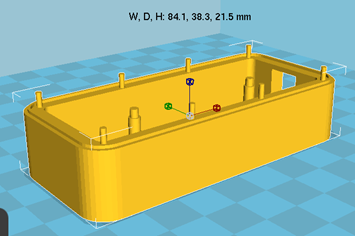
In addition to the automated triggering, I wanted to keep the manual button function intact in case an override was necessary. Since the ESP8266 dev board required a little extra space, I created a 3D printed enclosure to replace the bottom half of the original RF remote. The new enclosure was about 20mm deeper to account for the ESP8266, the USB mini cable input, and extra wires.
During testing, I found that the RF signal was strong enough to trigger the lights even when the remote was buried in a closet. Therefore, rather than use a battery pack, I connected the new remote directly to a USB powerstrip (5V, 2A) and used mounting tape to anchor the remote against the back of a cabinet. The NodeMCU dev board has an internal 3.3V LDO voltage regulator to supply the ESP8266 and can be powered from the USB micro jack.
Next steps / future improvements
- Since there’s no state information readable by the ESP8266 to tell if the lights are currently on or off, a photoresistor circuit could be added if positioned close enough to a bulb to differentiate “on” from “off”
- Currently, the code doesn’t account for daylight savings. Since I made the UTC offset value a variable, a simple if statement could be used to check the date and vary the offset value if the date falls inside or outside the DST calendar dates.
 timabram
 Michael Möller
 Vishnu Mohanan
Any chance you'd be willing to share the 3d printing source file?