-
North pole connection revisited
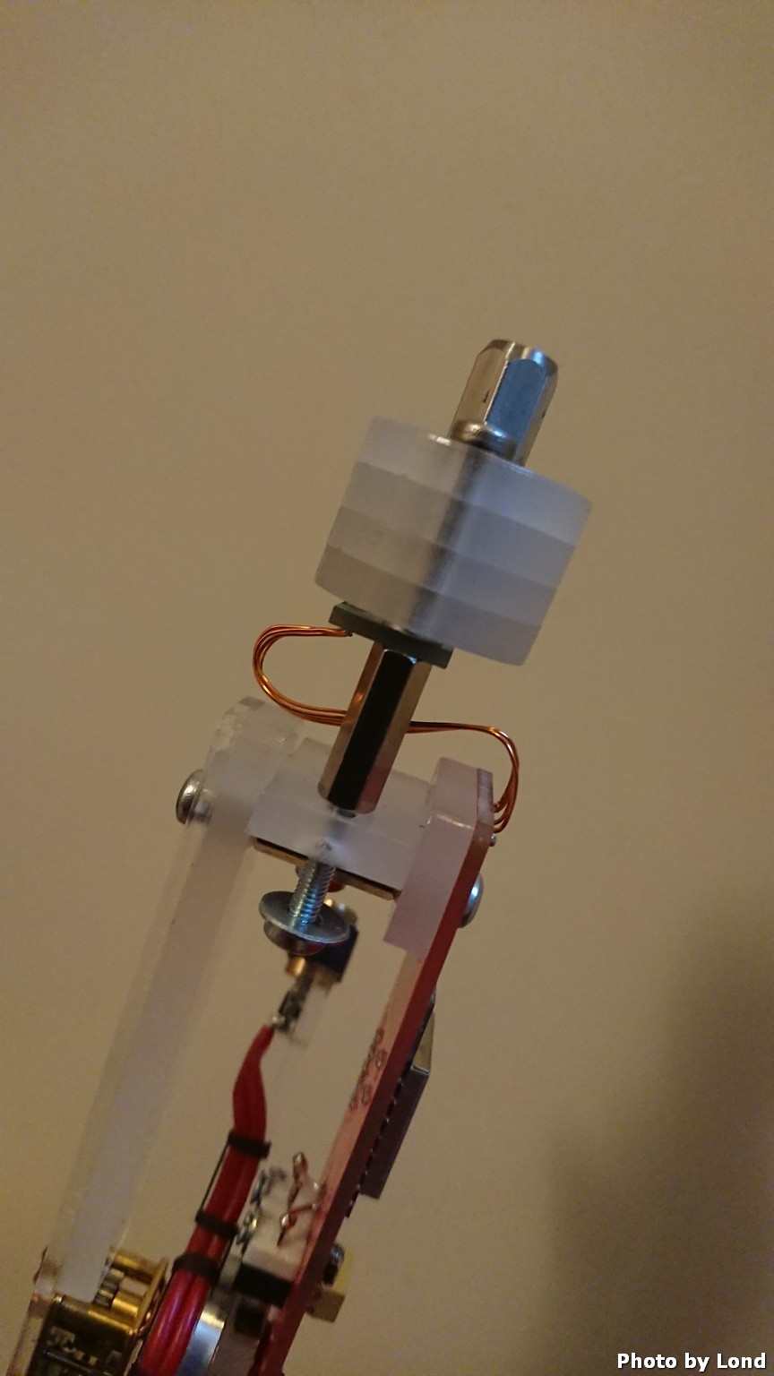
07/01/2021 at 19:33 • 0 commentsAfter getting the electronics to work I realized that the magnet in the north pole wasn't correctly aligned with the angle sensor and made the laser dot deviate +-5° when turning the earth globe.
According to the specification of the AS5600L, the maximum allowed displacement of the rotational axis of the reference magnet from the center of the package is 0.25 mm when using a magnet with a diameter of 6mm. I'm using a magnet with a diameter of 10mm, I think that I shouldn't deviate more than 0.25mm anyway...
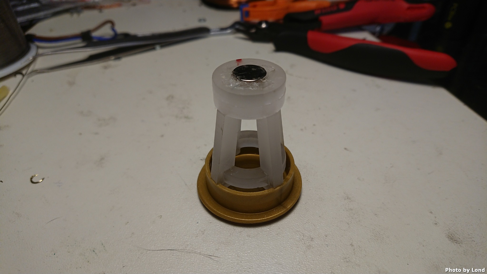
My solution was to mount the magnet on a axel and a bearing that is fixed with the sensor
![]()
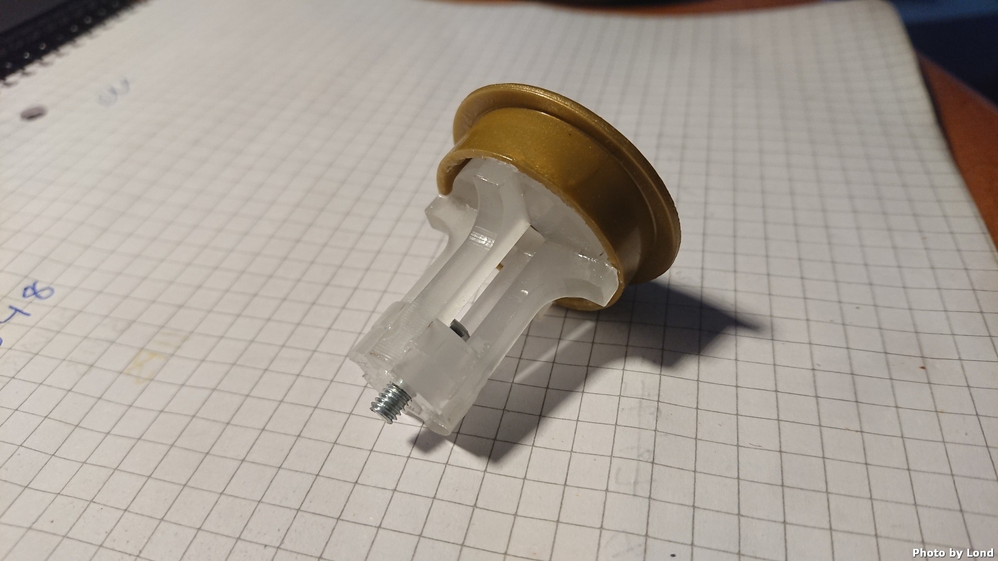
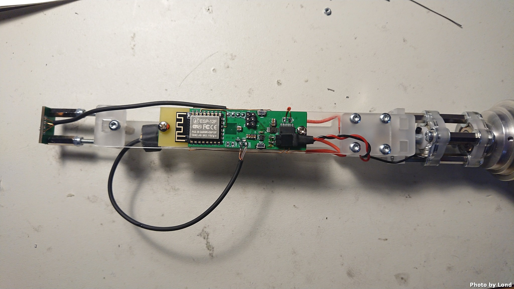
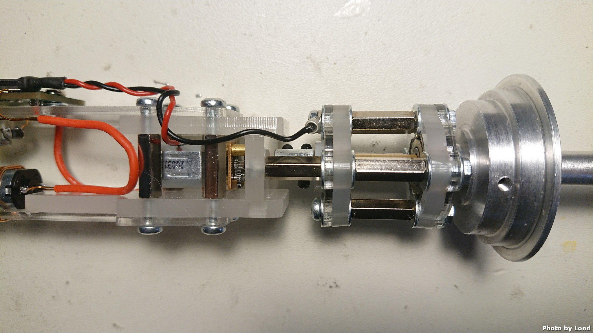
And to make the magnet to rotate with the earth globe a new north pole connection was designed
![]()
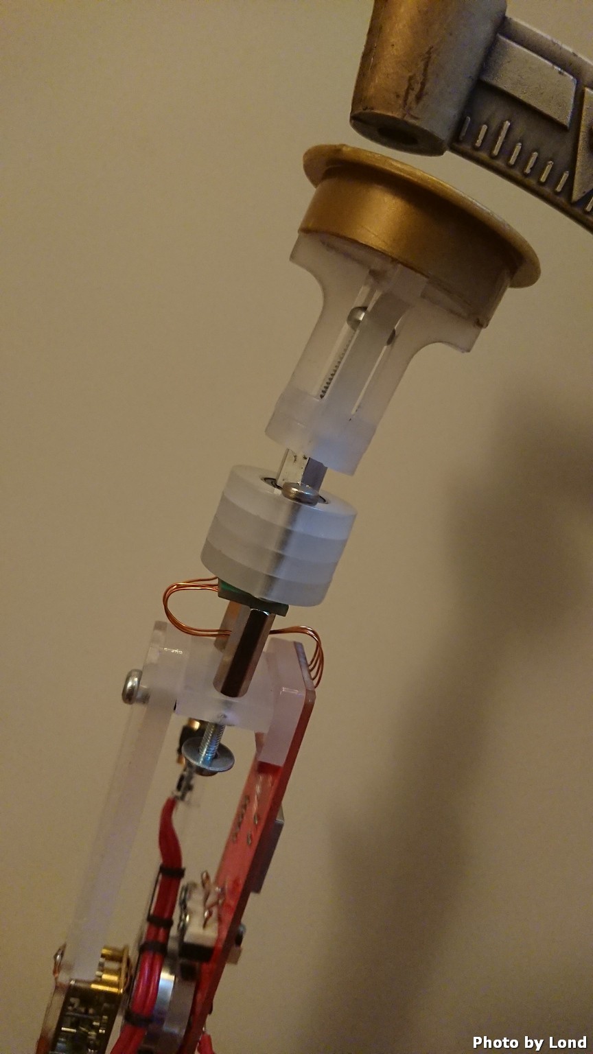
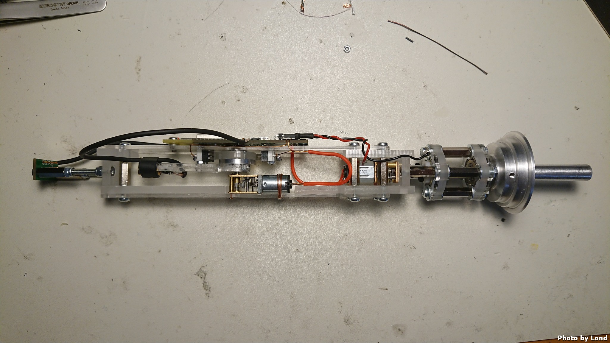
And here without the earth globe
![]()
And after this design change the deviation of the laser dot isn't noticeable at the equator :)
I can now continue with the user interface...
-
Assembly and testing
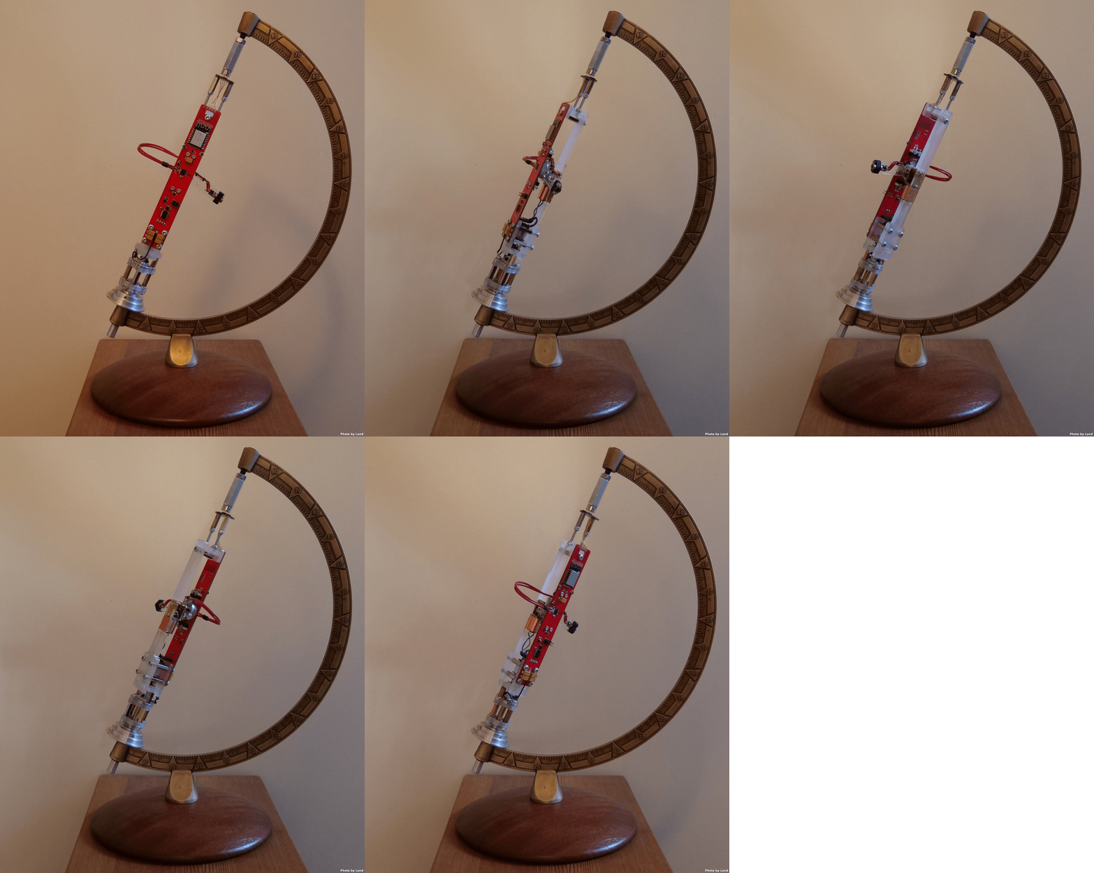
06/26/2021 at 10:30 • 0 commentsIt's time to assembly the unit inside the earth globe...
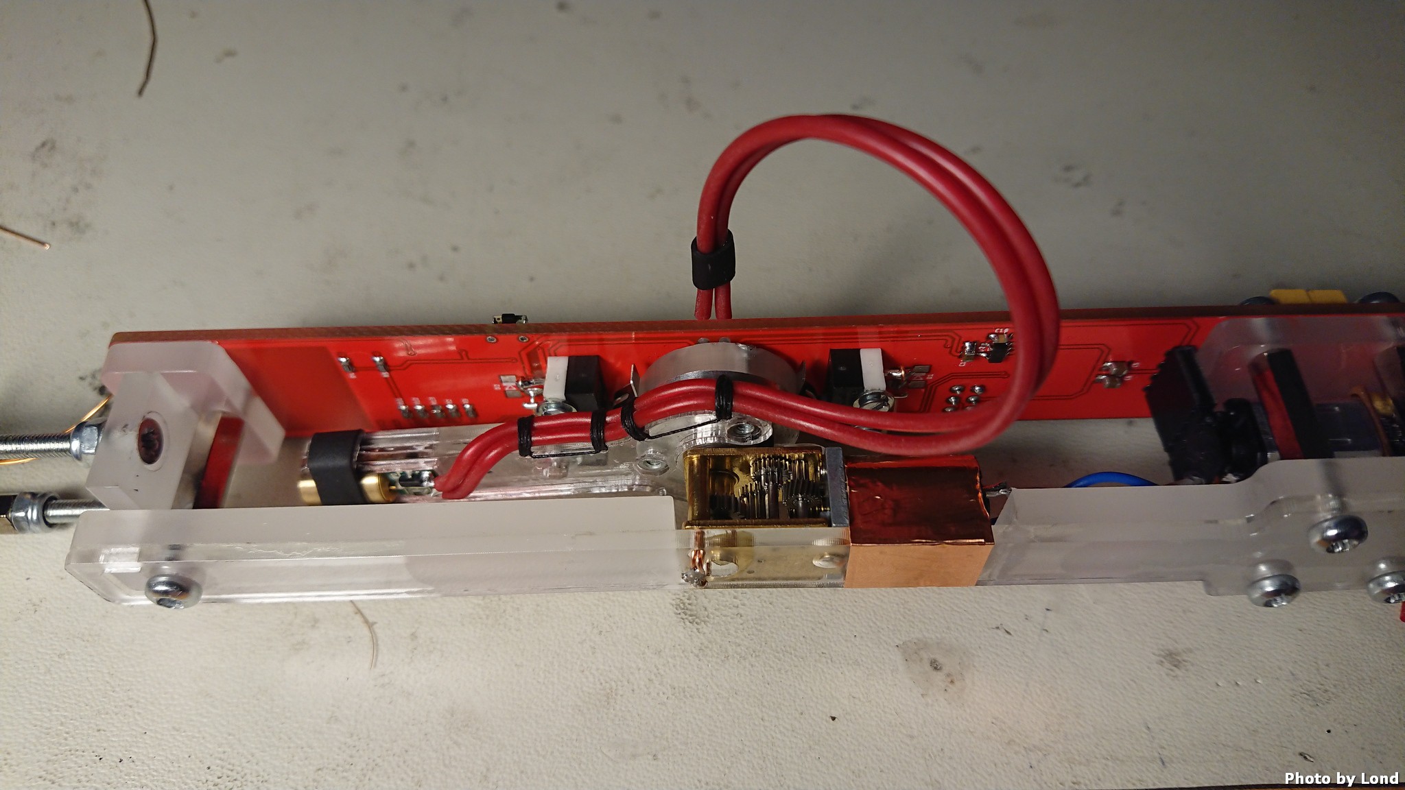
![]()
The screw and nut assembly with a magnet attached simulate the earth globe.
Everything seems to fit, lets power it up..
And now with the earth globe attached..
This was the easy part :) Let the coding of UI and MQTT begin......
-
Positioning the laser
06/24/2021 at 19:18 • 0 commentsTo guide the laser to the correct position I'm using magnetic angle sensors (AS5600L) to feedback the control loops for the motors. For the longitude movement it's easy, just add the magnet on the rotation centre of the laser arm. For the lateral movement it's a little more complicated because the earth globe can freely be rotated around its polar axis...
The solution is to modify the north pole mount and add a magnet that then becomes fixed to the rotation of the earth globe.
![]()
The µP will now always know how the earth globe is rotated..
-
Electronics
06/24/2021 at 18:51 • 0 commentsA project like this need a custom PCB that fit space constrains...
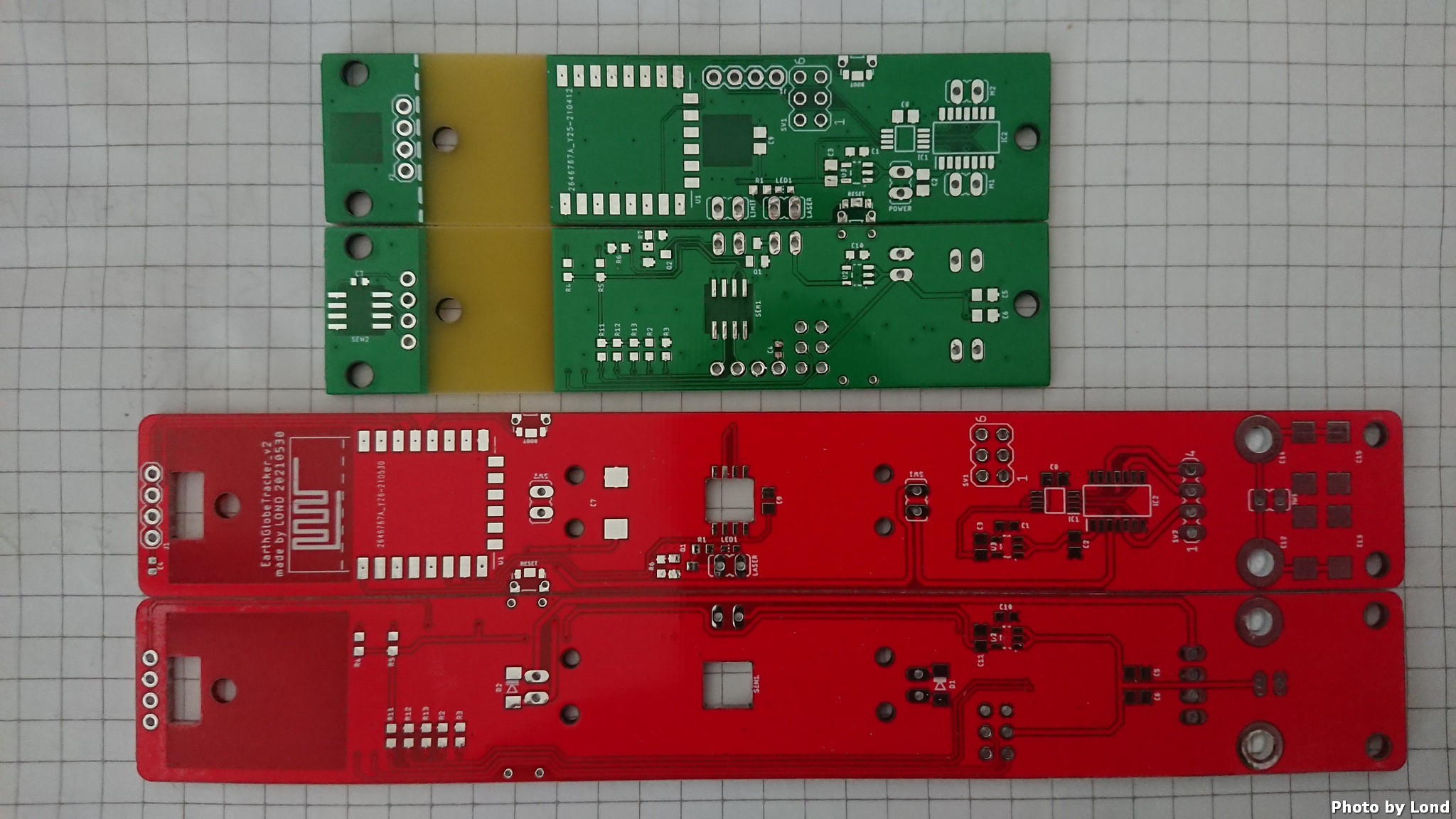
The first version of the PCB had all of the necessary components and functions for testing and some function that didn't work...
![]()
The first design version of limiting the rotation of the laser arm didn't work as plan and the µP got stuck in reset... The second version was better with the switches in series with the motor and diodes in series with the switches so the motor still can reverse back from the limit switches.
![]()
The power feed from the DC-input is routed via the motor case (positive) and through the bearings (negative).
![]()
After the bugs and design flaws was sorted out, it was time to design version 2 of the PCB.
![]()
The version 2 have integrated limit switches and reverse diodes and a combined connector for both motors for easier cable management. It also have more capacitors for increased stability on the power input, not that I have noticed any problem, but when there is space then it's space for more capacitors....
One other change in version 2 is the dimension of the board, I discovered that the 2mm thick laser cut Plexiglas was to flimsy and needed reinforcing. To save space I decided to integrate the PCB as a structural part of the design.
![]()
The major components on the PCB is:
- ESP-12F µP module
- 2 x AP2202-3v3 LDO:s
- PCA9633 i2c to 4 PWM outputs
- LB1836M dual full bridge low volt motor driver
- 2 x AS5600L magnetic angular sensors, i2c connected
- 2 x limit switch
- And of course resistors, capacitors, LED, a transistor and connectors
Did I mention that the version 2 PCB is RED?
-
Move the laser up and down
06/23/2021 at 19:45 • 0 commentsNext task was to design the movement for the laser up/down (latitudes). The laser need to have its rotation centre in the centre of the earth globe for the easiest control.
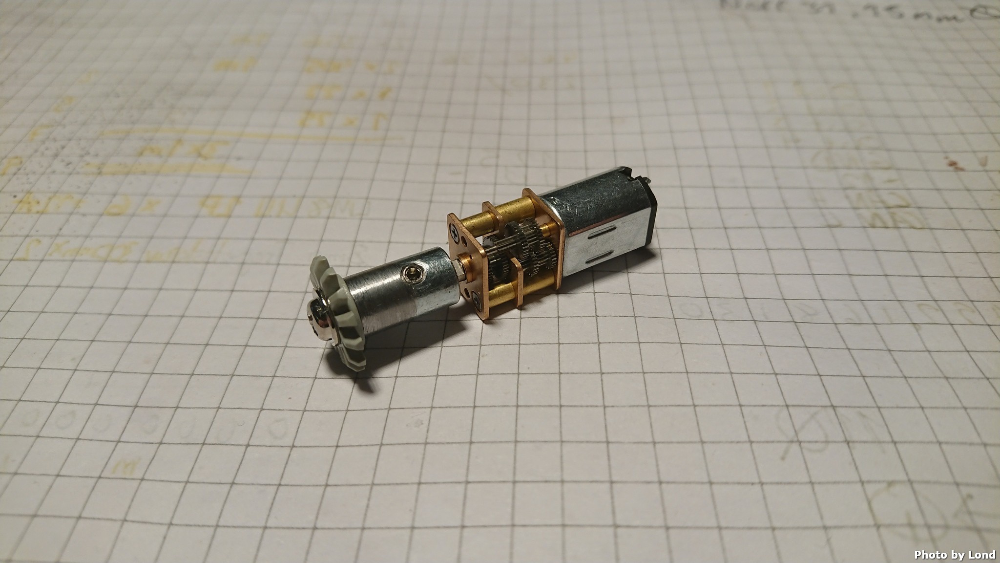
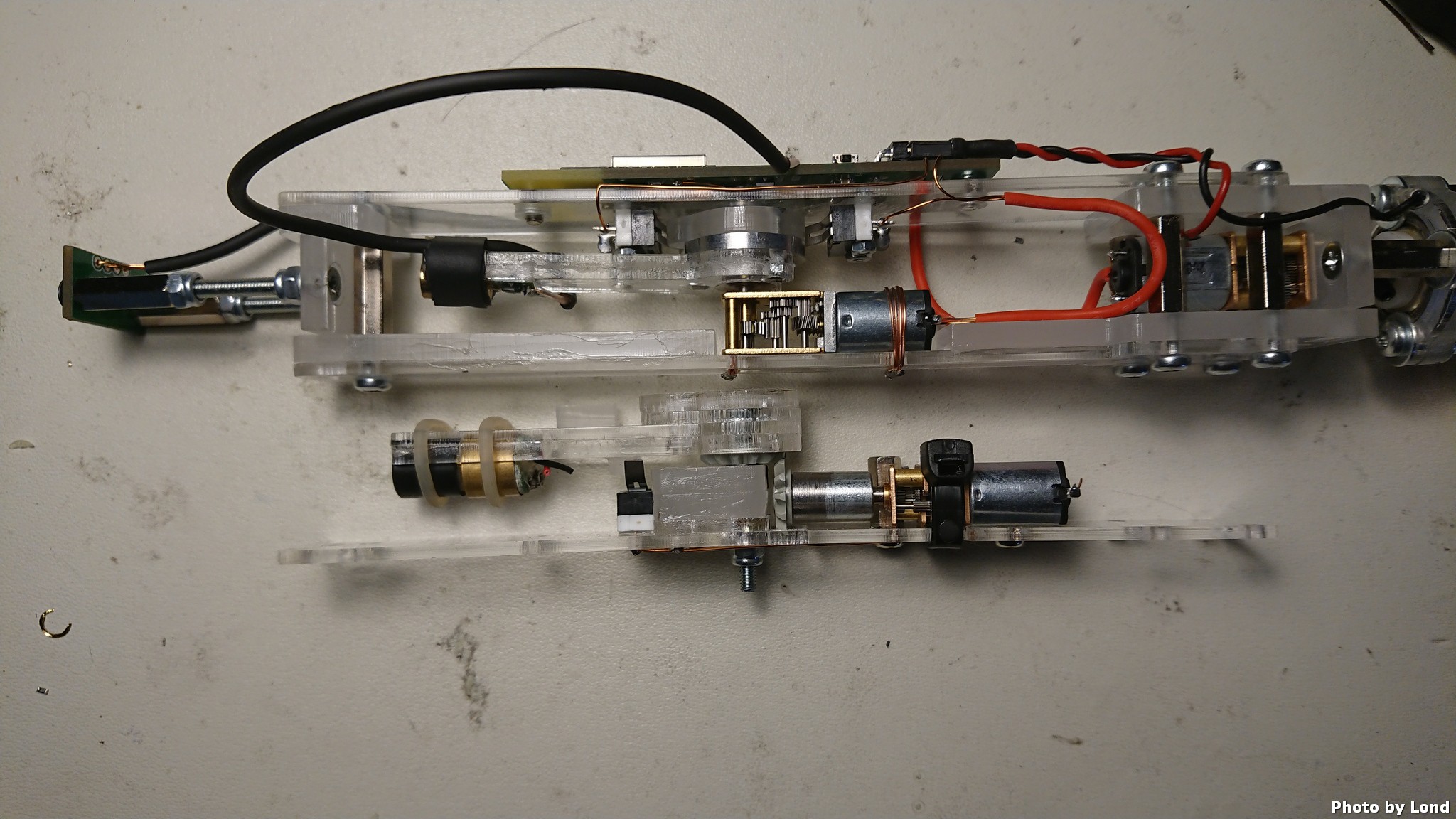
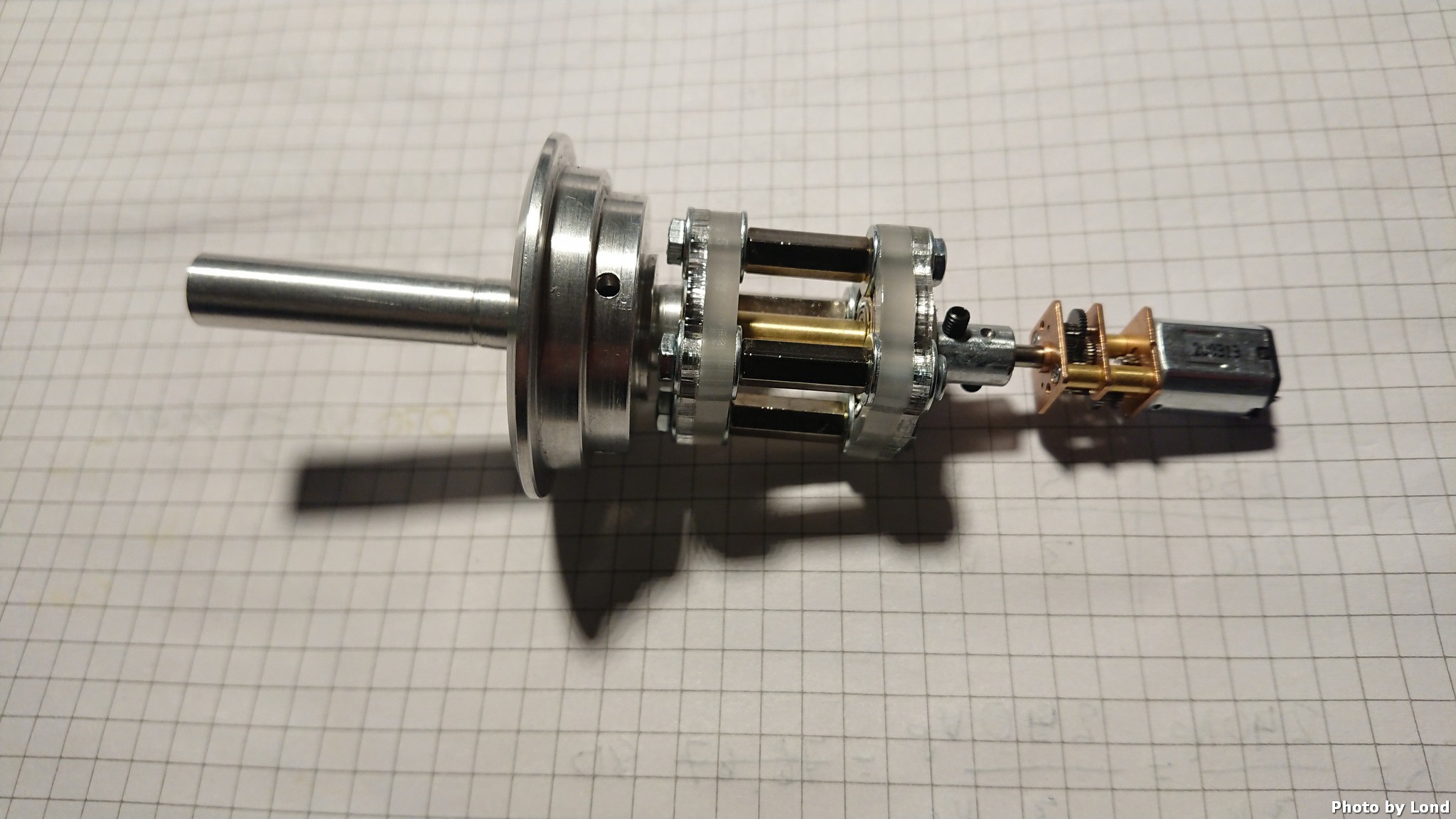
Because I couldn't find a motor with high gear reduction and right hand output with short lead time, I started to design my own with a 1000:1 motor and LEGO gears.
![]()
Unfortunately the result was not perfect and I had to order correct motors from China, that halted the project for a couple of weeks...
But the new motor was worth the wait.
![]()
The difference of the two motor designs.
-
Creating the mechanics
06/23/2021 at 19:17 • 0 commentsTo be able to control the laser dot I need to create a drive mechanic that would fit the lamp hole of a earth globe. My 300mm earth globe have a 38mm hole in the bottom that everything need to fit through.
I started with making a CAD model of what space I had and begun to design the bottom mount that will hold everything inside the globe and also pass the power to electronics.
![]()
This is what I come up with, an aluminium part that replaces the lamp mount and have DC-input in the bottom. The centrepin of the DC-input is coupled to the output of the 1000:1 reduced motor, which causes the motor housing to become DC positive. DC negative is passed through the bearings that makes the mechanics to freely rotate without any limitations.
-
The first idea
06/23/2021 at 18:56 • 0 commentsThe idea comes from that I'm planing to buy a boat and sail around the world and want to show my family where I'm in an easy and low tech way. I'm planing to go full electric with a lot of technology and safety feature, for example a GPS live tracker.
The earth globe will fetch the position information and display it with a laser dot on the globe.
