-
Manufacturing Case
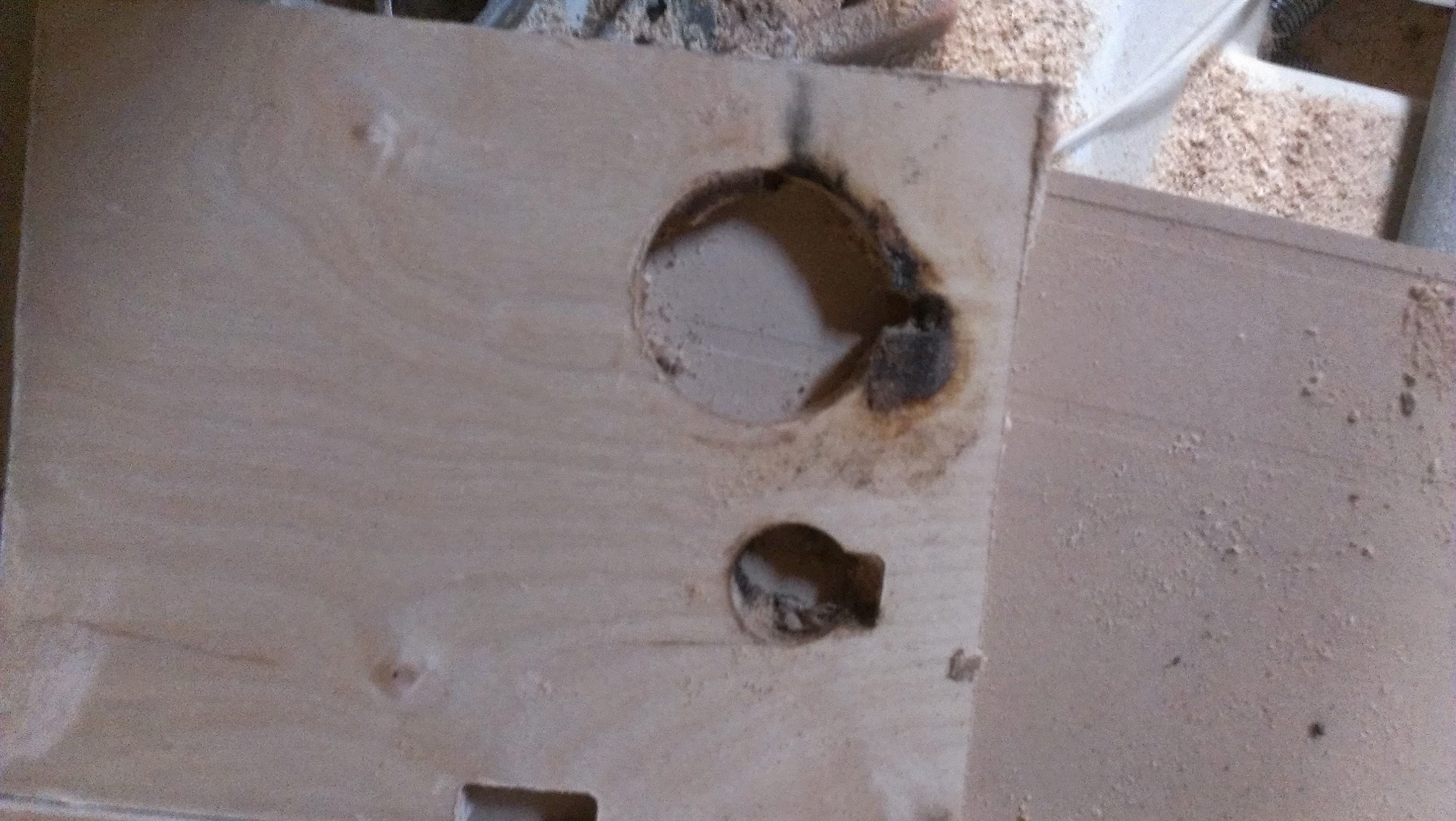
10/09/2015 at 22:49 • 0 commentsI used a cnc router to manufacture the structure of the coil winder out of MDF. At first when I was trying to make sure the program works, I was running the router really slowly. A really fast rpm along with a really slow feed rate caused a small flame.
![]()
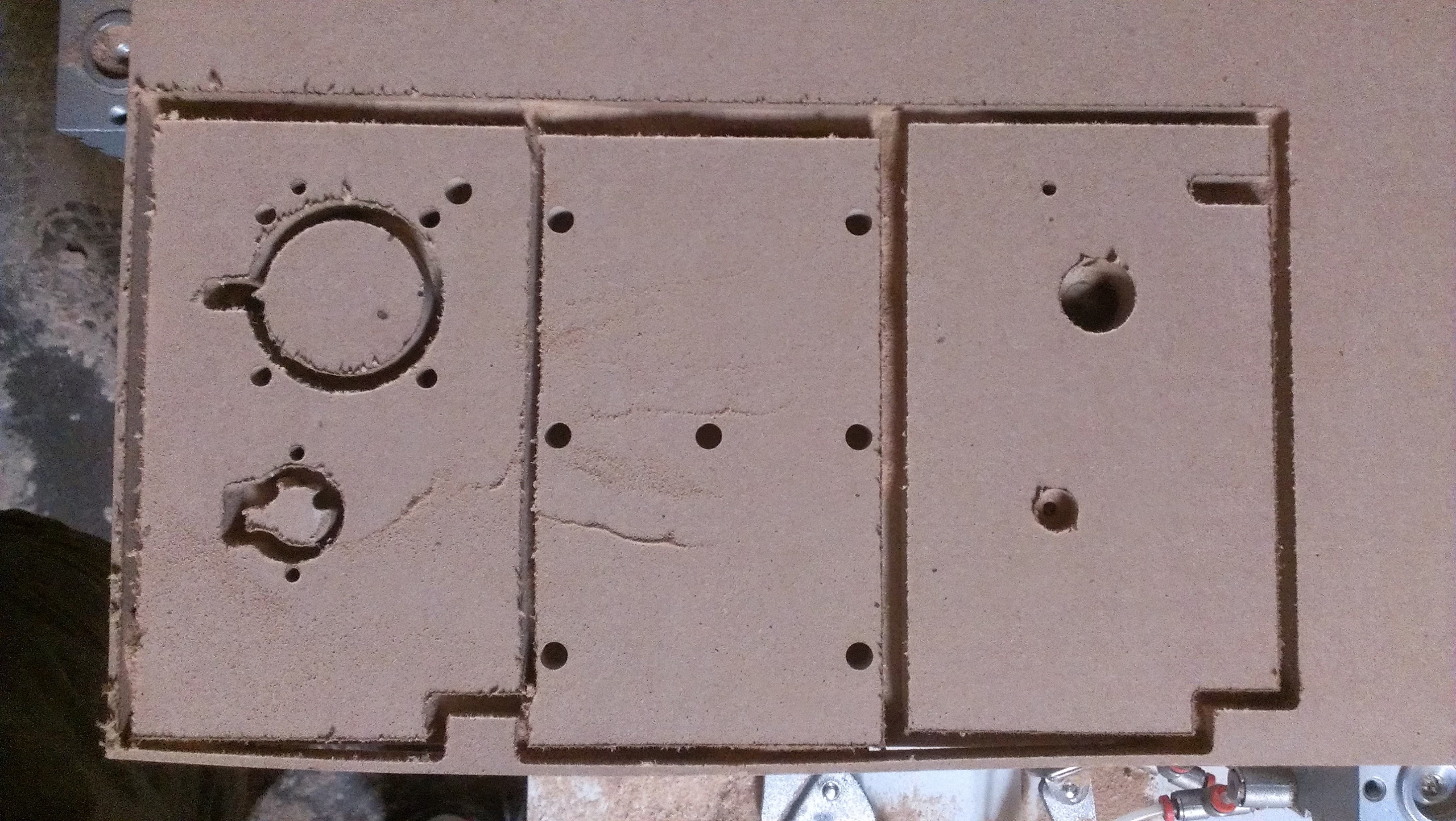
After that small road block I managed to router out the parts.
![]()
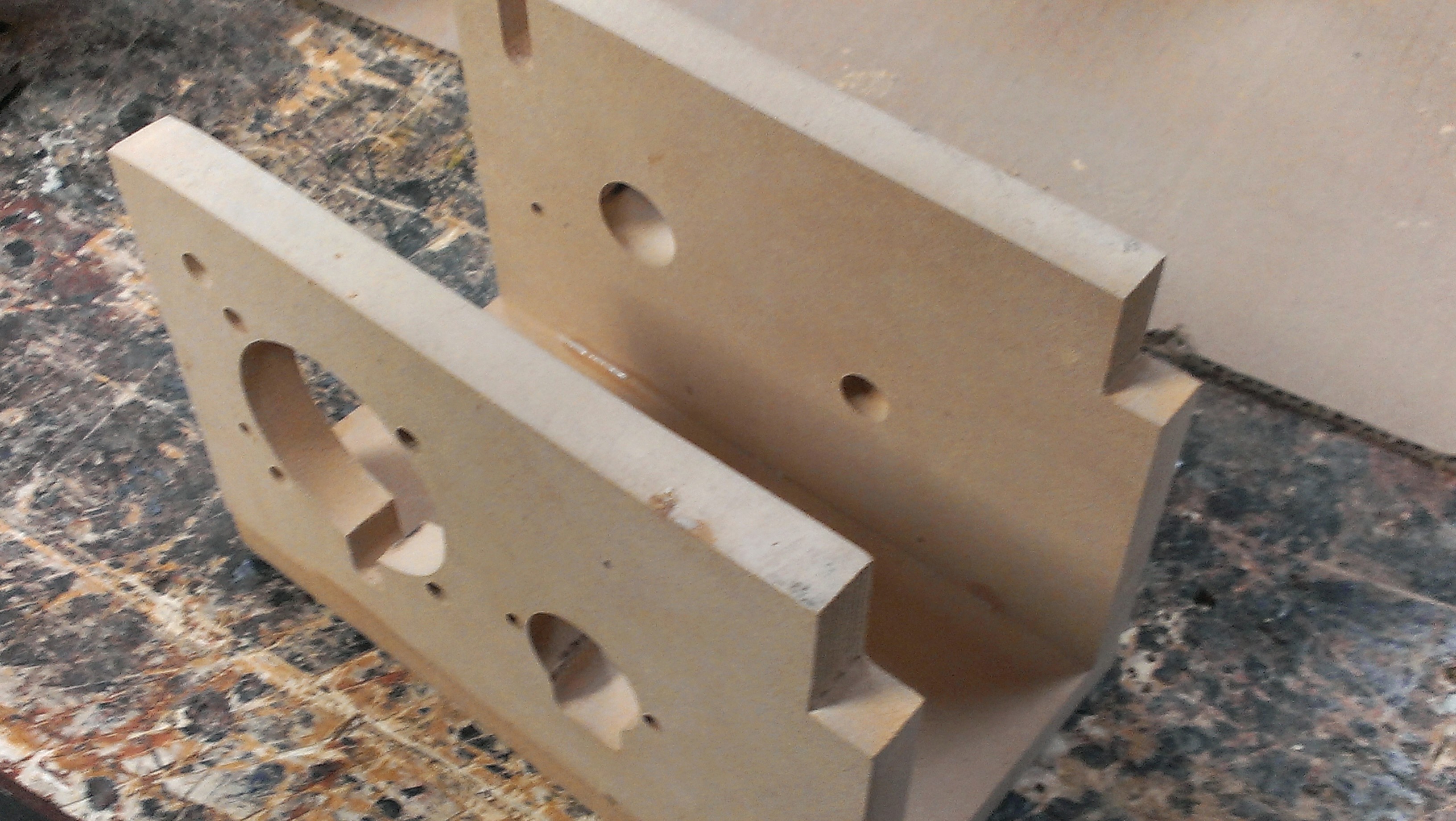
Then with some wood glue and dowels I made a sturdy case for my machine.
![]()
Now the case is ready for mounting the electronics.
-
Design
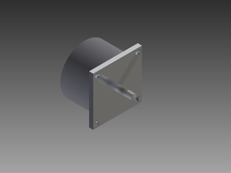
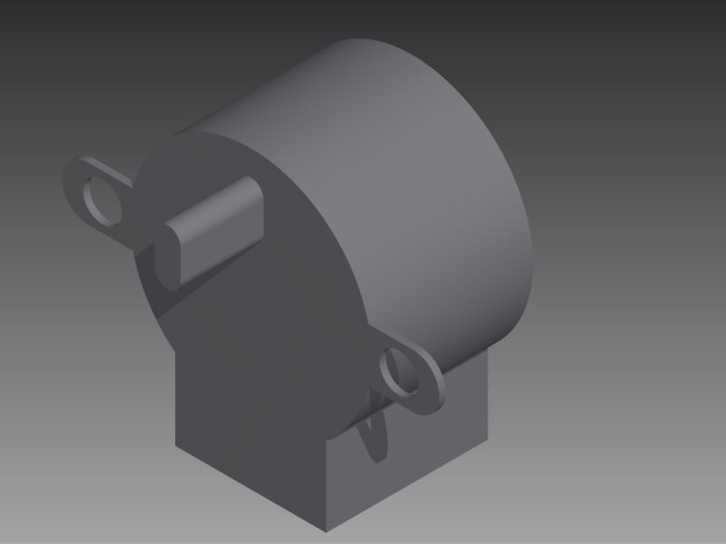
07/07/2014 at 03:32 • 0 commentsTo begin my design process I found some old steppers I had and designed them using Auto-desk Inventor.
![The stepper motor that will turn the core]()
This is the motor used to turn the core
![]()
This stepper is used to turn the lead-screw, which adjusts the horizontal position of the wire
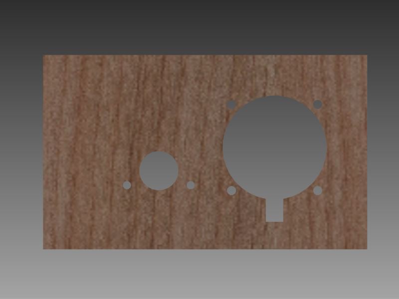
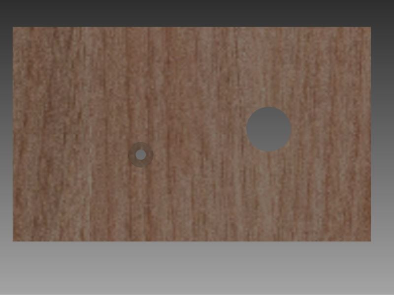
After the motors, I made the frame of the entire machine, planned out where I wanted the motors, and designed the frame.
![]()
The wall of the structure where the stepper motors will mount.
![]()
The opposite wall, where the ball bearings will go to support the shafts.
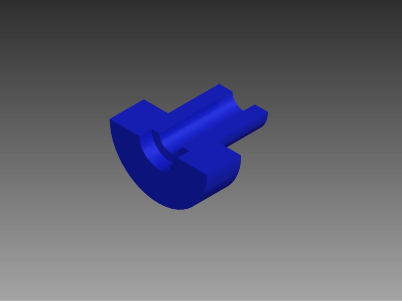
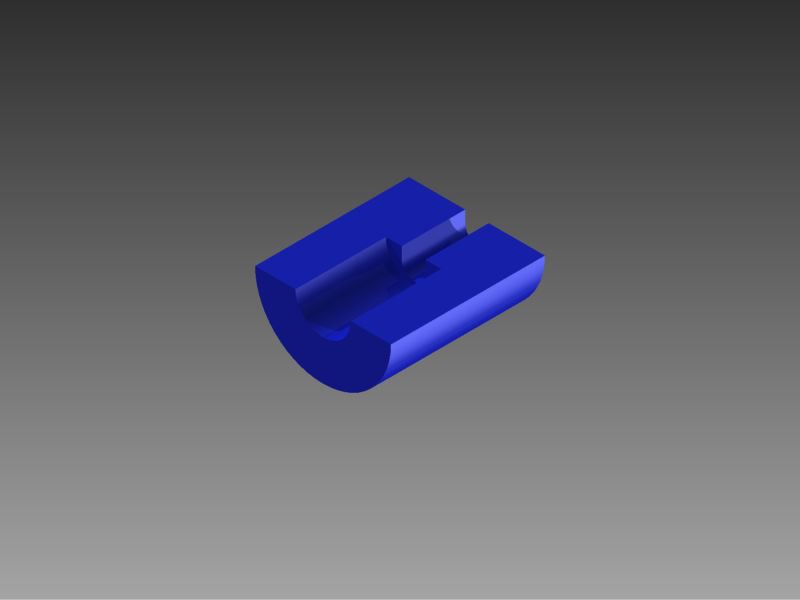
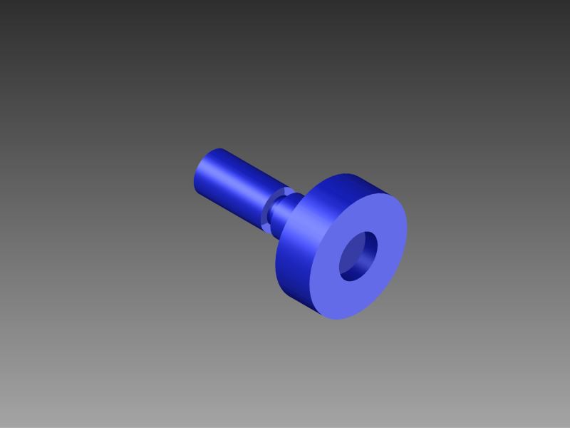
After designing the frame, I began designing the 3D printed parts there were a total of 3 parts.
The following two renders, are cut in half to allow easier viewing.
![]()
This is the piece that connects the main stepper motor to the core.
![]()
This is the part that connects the smaller stepper to the screw I will be using as a lead screw to control the horizontal position of the wire
![]()
This is the piece that connects the core to the ball bearing opposite to the main motor.
-
Pre-Design
07/07/2014 at 01:46 • 0 commentsBefore beginning the project, I needed to figure out what features I need to have in the mechanism. So I 3D printed some pieces to hold on to the core so I can experiment with winding a coil by hand on a lathe. After a couple hours of winding, and unwinding coils, i figured out I needed at least two moving parts, one to rotate the core, and one to move the wire horizontally according to where the wire needed to be wrapped. With those design limitations I began designing in Inventor.
![]()
![]()
Coil Winding Machine
To make a machine that winds coil around a steel rod to make an electromagnet.
 Jack Najarian