Jianjia Ma
-
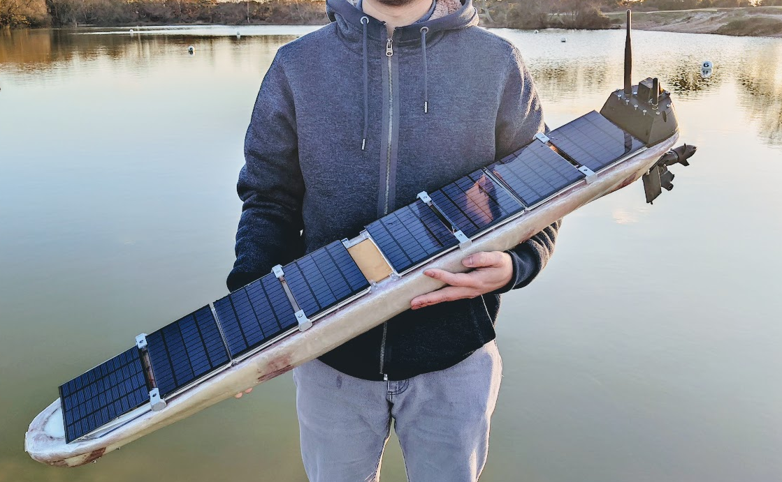
First experiment at Setley Pond
03/09/2022 at 09:38 • 2 commentsDid an experiment at Setley Pond, New Forest this Sunday afternoon 7th March 2022.
![]()
In this experiment, I would test a few different things. Including
- manual control and motor drive.
- underwater wings. (cancelled, due to no wave)
- waypoint mission. (cancelled, due to low rudder effectiveness)
As you expected, this experiment wasn't going well. Fortunately, the boat floated and recovered. Also, data are recorded so we have something to analysis.
The motor can really push the quite fast, even the throttle has been limited to 50%. The motor consume around 5 Amp current at 50% throttle. When I pushed the throttle fully from the App (50%), I am quite worry about the boat sinking into the water and become a submarine... Beside the boat was not being able to turn, it is really fun to play with.
![exp1_boat_video.gif]()
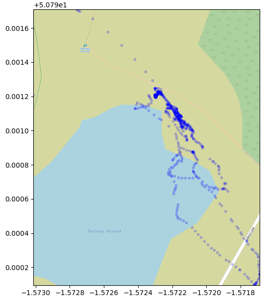
Trying to plot the GNSS location in a map, but due to the EMC problem that discuss below, the GNSS can only be located by 4-5 satellites during the trial, the accuracy is pretty low, the path is meaningless.
![]()
In the next sessions, I will show the issues that found during the experiment and some of the solutions.
Issues
EMC issue
At the experiment, all antennas are placed in the bridge at the tail of the boat.
SIM800C's antenna is placed closed to LoRa's antenna, even in the same direction. What makes things even worst is they are working at a similar frequency band 800/900M for GSM and 868M for LoRa. It was ok during the home test because the city area has better cellular coverage so the GSM module won't emit too much power. But in the rural, it starts to emit more power so the LoRa is now struggling to send/receive data.
GPS module also suffered from the GSM module's RF. From the data it recorded, I can see there is only 5 satellites connections when the boat was on the surface of the water, where the signal is weaker. But when I recovered the boat and raised the boat to my car's boot, then it can see 10+ satellites.
The potential solution is to move the GSM module and its antenna to the bow of the boat.
For the Iridium, I think it will be ok to stay at the tail bridge because it won't be activated too much.
The GSM module cannot be placed at the mat because the QingStation uses BME280 for pressure and humidity measurement, which is RF sensitive.
![exp1_sat.png]()
Water leaking issue
There was a half cup of water found after I returned home. It is fortunate that I remove the battery from the controller board before I set off. I had to dry out the batteries because they are wet.
I think it might come from some screw holes that I did not put a screw in. Hopefully, I can fix that later.
Servo found dead
One of the servos, servo 1, left rudder, was found dead just before deploying the boat. I supply direct battery voltage to the servo, which is 8V currently, the Servo's working voltage was rated at 4.8 to 7.2V. Looks like it burned out the servo. I disassembled the dead servo but couldn't find a burning spot on the controlling PCB. The reason of the failure remains unclear.
I order a few mini-360 step-down DC/DC boards to lower the voltage and a new servo to replace the dead one. I would set the voltage to 5.5V. The recorded peak working current for these servos is less than 1A. I believe the small DCDC board can handle the servo's current.
Low rudder effectiveness
This issue is partially related to the dead servo, but also the length of the rudder is underestimated. I did try to build an extended rudder that can stick on the existing rudder which I brought long time ago designed for RC boat.
The range of servo is set to +-30 degree, which seems too narrow. It is now increased to +-60. The actual angle that the rudder can turn is smaller than servo angle.
With only one working rudder, the boat can barely turn at high speed. I think that is because the motor was placed far behind the rudder. The blue highlighted part is the new extension that will be added to the rudder.
![rudder_extension.png]()
ESC response too slow
I added a smooth throttle response in the software to eliminate the immediate change direction of the motor. But the value is too large. Adding some signalling delay, the boat feels out of control many times, did not respond for 5 seconds, while I did hear the servo is still responding to my command. Easy fixed issue.
Batteries magnet field affecting magnetometer
Fixed by moving the battery forward.. 10 cm away from the controller box.
Boat mass centre too high
Due to the heavy solar panels, the decks and the screws to fixed the decks, the mass centre were lifted too high, resulting in unstable roll motions. Even the propeller rotation cause 20 degrees rolling.
I brought 1.8kg lead ingots for ballast, each 450g. I will attach 900g to the bottom of the boat hull. When the keel is ready, I will then move them to the bottom of the keel for the best ballast.
Camera data error and image over exposure
Due to the low-frequency clock, 2.5MHz, while the OV2640 require at least 6MHz. The OV2640 seems cannot automatically adjust the exposure time (not short enough). The signal length is too long, about 30CM, any clock higher than 2.5M will not work. It is already producing quite a lot of byte error at 2.5M, see images below.
I will turn the software while keeping the frequency low. If there is no way to configure it, I will try to attach a grey scale filter on the lens to lower the lights.
![exp1_onboard_cam_set.png]()
-
Navigation for wing sailing
02/23/2022 at 22:14 • 0 commentsNavigation
Navigation is a challenge for a small boat like DeepPlankter.
- The ship might equip with a free-rotated wing. Headwind and tailwind will generate little-to-no force. The boat needs to offset to the wind direction.
- The propulsion (from wing or wave) is small and unstable. It can even be pushed back by wind or sea current. The navigation should be able to drive the boat back in this situation.
- The boat cruising speed is very low.
Simulator
The source code is available in the dedicated navi-sim repo
To ensure the navigation algorithm works as expected, I actually build a 2-D simulator out of Processing 3. Processing 3 is basically a java graphical lib with some customized interfaces. This simulator is extremely helpful for me to develop a navigation algorithm.
Up until today, it has the features below:
- Ture earth coordination
- Dynamic wind simulation [direction, wind guest, wind speed]
- Dynamic sea current [direction, speed]
- Drag
- Boat physical model
- Interactive waypoint
- Time wrapping
Although most of them are very simple, they still can cover the most extreme situations such as strong wind, guest wind and strong current.
![nav-sim-loop.gif]()
Navigation strategy
Different drone navigations algorithm have been widely implemented on many open source flight controllers. Actually, most of the opensource flight controllers use the so-called L1 navigation algorithm (original paper) or its variances. It is robust and has already been validated by a lot of experienced users.
The most significant principle for L1 is it uses the term "the acceleration back to track" (a_s_cmd) as the key parameter to control the course correction. Also, in many L1 implementations, they assume that η is a very small number so sine can be replaced by linear functions. L1 give drones a very good track following method no matter the track is a line or a curve. It is also very simple to tune because there is only one parameter called L1, which define many things. Such as the track width, the damper for the stay on track acceleration, the length of line-of-sign to track, and others. Here is the L1 principle (figure copyright belong to the paper author).
![]()
The question for me is whether I should implement L1 or develop a specific algorithm for the boat. There are some considerations:
-
Compared to air drones or rovers, the boat I built is aimed to low speed ( < 2knots) but also at very large scale waypoints (10-100km). The "stay in track" capability is not very helpful since the track can be very wide(100m or ~km).
-
The navigation should also implement the zigzagging algorithm when the boat is heading into the wind direction or away from the wind direction. Otherwise, the air wing give us little to no propulsion or even drag.
-
The boat will also likely be in extreme situations such as strong wind and current in a storm. It is not clear whether the L1 can handle that. (not sure my algorithm can either)
-
L1 use only one parameter to define many terms that are used in the algorithm. This is not very feasible for this boat navigation situation.
To sum up, using L1 here will not be ideal, since we are not taking advantage of the following track or the simplified parameter setting. Instead, we still need to have finer tuning parameters such as track width and others.
We are more interested in large scale direction, for example, the path width can be 100 metres or ~km when in the ocean. Compared to these distances, the boat speed or accelerations seem very small. It is unnecessary to wake up the actuators to do a small correction. We only care about whether the boat is heading toward the right direction in a long time scale (minutes or hours.)
Track following
However, track following is still needed, as the distance between the waypoints can be too long, simply heading to the target waypoint will have very limited resistance to interference such as wind and current. What we don't want is not try too hard to get back to the track, which consumes our limited battery power. For the track following, unlike L1, I use a P controller on the cross track distance to get the course correction back to track. This correction is also limited by a fixed threshold, called max_offset_angle, this is normally in the range of 45 deg to 70 deg.
![nav_track_follow.png]()
This is a very simple P controller, but the P setting will be very low so I am not too worried about oscillation. In the actuator output implementation, there are also heavy filtering and lazy responding implementation, so a small correction will not trigger the servo action (servo will be power down most of the time to save power).
Out of track detection and secondary track
Out of track detection calculate the track distance to the primary track. If the distance is larger than n=3 times of track width. The boat will no longer sail follows the track to the primary target. Instead, it creates a secondary target waypoint on the primary track. Then it starts to follow the secondary track to get back into the primary track.
This seems unnecessary because the track following always drive the boat back to track. However, it is very useful for wing sailing which we will discuss in the next section.
![nav_out_of_track.png]()
The insertion point (the secondary target) between the secondary track and the primary track is defined by the boat's current location and the max_off_angle, the angle is set to < 90deg. At least, it will not go backward.
Simulation :
![nav_sim_sec_path.gif]()
To be noticed that we use heading instead of course for this calculation for simplicity. It is expected strong current will push the boat out of track quite often. But as I mention, we are not aiming for an extreme track following.
Also, the parameters we use do not contain derivative components (speed or acceleration), but we assume they are very small values compared to the waypoints and distance which hopefully make the parameters tuning cover most of the case. So, we don't need to do filtering because derivatives can be very noisy.
Navigation with air-wing
We know that sailboat cannot sail directly into the wind, there is an angle threshold where the wind propulsion drop dramatically, when the wind direction changes from side to the headwind. Sailors call this no-sail zone.
![nav_sail_zone.jpg]()
For free-rotate wing sail, there will be another zone for tailwind.
Many researches have been done with wing sailing, such as Design of a free-rotating wing sail for an autonomous sailboat by CLAES TRETOW. Below is the polar diagram from the thesis.
![nav_wing_polar_diagram.png]()
This graph represents the wind direction (relative) vs boat speed. It is symmetric for the left and right sides. Here we only discuss the wind from the right. We can see that the boat start to struggle when the wind direction is over 150 deg (tailwind) or less than 30 deg (headwind).
I assume our boat has a similar diagram, so our navigation has to be able to void sailing into these "no-sail" zone. When the course to the target waypoint is close to the wind direction, we need to sail in a zigzag pattern to approach while avoiding sailing into the zone.
![navi_sim_zigzag.png]()
I considered the below ways to implement the zigzag path.
-
Add temporary waypoints to form zigzag path + strict track following (such as L1).
-
Allow some free sailing zone within a large track.
For the first method, adding temporary waypoints requires extra calculation and waypoint management. Also, it is not responsive when the wind direction changes during the temporary path. When generating a temporary waypoint, require stable wind direction measurement. This method requires many measurements which will increase the complexity.
For the second method, as I mentioned in the above sections, our navigation method has a large track width. So as long as the boat is on the track, it is free for the zigzag method to decide where to head. The zigzag method can decide the heading freely according to the current wind direction and wing angle. This method decoupled the zigzag algorism with navigation algorism. which make it easier to design.
The below diagram shows the second method. When the boat is within the track, it can sail freely in any direction, and of course, the zigzag algorism will navi the boat following the edge of the "no-sail" zone. When the boat finally reaches the boundary of the track, the track following algorism will override the zigzag output and turn the boat back into the track immediately.
![nav_zigzagging_path.png]()
There is a path shrinking angle that will shrink the path near the waypoint. This angle is normally set to arctan(2).
In this zigzag mode, the "no-sail" zone is dynamically updated, depending on the wind angle measurement (which is relatively reliable). It is very good because the "wind direction" that we use is the relative direction, which combines the boat motion and the real wind motion. So it can continually update the heading to archive good wing efficiency.
Zigzag algorithm
The zigzag algorithm is very simple. When inside the track, the zone is free for zigzag to decide where to head.
We first use the current wing angle to see if it is in the no sail zone. Then compare it to the course to target waypoint. If we will turn into the no sail zone, then we cancel the angle out so the boat follows the edge of the zone instead. It will continue to sail this until it reaches the other side track border, where it will reconsider which zone edge to follow.
![nav_zigzag_ani.gif]()
Code implementation
Please refer to the firmware repo or the simulator repo for the implementation.
Simulation in an extreme situation
Finally, this is the simulation in frequently changed wind direction.
- added 20deg P-P wind direction noise (every cycle)
See the top-right corner arrow which indicates the average wind direction (the actual change of wind direction is much quicker). See also the "wing effi" statistics on the right-hand list, which records the percentage of time that when the wing is outside of "no-sail" zone (means the wings is effectively providing propulsion). The route that boat is changing very frequently to allow the wing in high-efficiency angles. Sometimes it even sails the boat backward.
![]()
Overall, this navigation method can drive the boat to the destination even in an extreme scenario.
You can run the simulator yourself by downloading the code from the simulator repo. The environment can be changed through the source code.
-
The underwater wings
02/17/2022 at 02:04 • 0 commentsThe underwater wings are to convert the vertical motion (wave) of the hull to small forward propulsion. So the boat can sail forward without the need for energy.
I was planned to build the wing core from wood pieces. Cut the shape, then sand it down to streamline. But later I decided to let the 3d printer build the core. There are some issues with 3d printed parts.
-
The PLA materials that 3d printer used might degrade in salt water ( which is not, later confirmed by research paper. )
-
PLA can crack easily.
-
If we reinforce with glassfibre and epoxy, the epoxy has difficulty to glue on epoxy.
To solve the second problem, we use a tough PLA to print the main part. For the third problem, I planned to use rough sand paper to sand it down and leave more scratches for the epoxy to grab on.
I didn't use a standard airfoil on the underwater wing but built from my own experience from RC planes. The airfoil is symmetric so it should perform the same for both upward and downward directions. It also has a small wing tip to lower the drag from induced drag (not sure whether this is useful but looks cool. )
![waterwing_root.jpg]()
![waterwing_half.jpg]()
Underwater wings are normally spring-loaded so the wing can work efficiently during different vertical motions. This paper by University of Southampton has thoroughly investigated the speed and different underwater setup.
![waterwing_speed_spring.png]()
Although, high springs loaded wing will produce faster speed when the wave frequency match the wing design. Load springs load has a much wider working range. However, the above data are from their testing design, in which wing has a larger chord (see the original paper for details).
I don't plan to use springs on the wings. It is hard to match springs. Also, I don't think it is necessary since our wing has a short chord, so it should turn to its maximum positive or negative angel very quickly where propulsion is generated.
If this doesn't work well, I will consider adding springs.
![waterwing_assembly.jpg]()
Today, the wings core are printed.
![waterwing_3d_printed.jpg]()
![waterwing_3d_printed2.jpg]()
![waterwing_3d_printed3.jpg]()
A 4 mm stainless steel axis is used. All weight and lift are loaded on the axis. This is where the wing will rotate on. This location is at the ahead of the lift centre, so the wing will lead to the vertical movement and covert the lift to the forward force.
![waterwing_3d_printed4.jpg]()
![waterwing_3d_printed6.jpg]()
The next step is to glassfibre this wing and the supported mount.
To be continued.
-
-
Building the hull
02/12/2022 at 12:41 • 0 commentsHull building
I have almost zero experience in designing neither building a boat hull. During the building, I made quite a few mistakes. But finally, something was built...
Hull designing
There are some points that need to take care of when designing the hull.
- The hull should be as skinny as possible. To lower the drag, also allow my 3D printer to print the segment (<18cm diameter).
- However, the deck area should be large enough to hold as many solar panels as possible.
A smaller boat requires fewer materials to build, which will always lower the cost. So I basically designed the deck that can host the minimum number of required solar panels. A single panel size 11 x 13cm, generate a peak power of 2W. Per the preliminary calculation, we will need at least 8 of them.
Since the boat will sail at a lower speed (< 2knots), a small displacement hull is enough. Here is the design.
![hull-3d-animation.gif]()
-
Total buoyancy: ~15kg
-
Displacement: ~8kg
-
Length: 1140mm
-
Width: 140mm
-
Height: 90mm
The hull has almost the same 140mm width for 90% of the length. Allows the panels to lay on most of the deck evenly. The front of the hull underwater part is a typical displacement hull design. I didn't pursue a narrow tip which is normally used in high-speed hull or RC model sailing boats. Because we still need a large top for the panels and the boat is too small which will easily be submerged in the incoming wave.
Also, the large top also increases the buoyancy when submerged in a wave. This increase the instability in a normal boat hull, which is not a good choice. However, with wave propelled wings, the increased tip buoyancy will lead to more lift on the front underwater wings. Thus, it should provide more propulsion. The lift loaded on the wing stabilized the boat.
The tail design also follows a similar principle of steep buoyancy change, with the bottom of the hull (at the end) being raised near the waterline. When a wave comes, the buoyancy will increase very quickly to pull up the tail underwater wing. At the tail, there was also a motor mount and the hull stick out for protecting the motor. But later found this is not a good design.
![hull_rudder_offset.png]()
We will have 2 rudders (for backup). Rudders are offset to the side by 15 degrees. It was meant for better steering during sailing. When the wind hit the air wing, the lift of the air wing will not only generate propulsion but also a side force (actually, the side force will be larger than propulsion most of the time). The side force will cause the boat to roll quite much. The offset rudder will be more effective compared to the regular rudder.
Hull building
After some search online, I decided to build the hull with epoxy and fibreglass. So I brought some 300gsm fibre chopped strands, 300 gsm cloth and 1kg epoxy.
I don't want to build a mould because it is too complex for me to do. I decided to print the hull using my 3D printer, then glue them together. Then apply a 3mm fibreglass-epoxy on the outside. Then sand down the surface to make it smooth.
The plan sounds ok but ends up with a lot of trouble!
-
First, the fibreglass chopped strands and cloth are too rough for a small boat like this. They cannot easily band during the corners. I have to keep bending it during the final curing hours. But the result is still not perfect. It also result in quite a lot of bubbles after I remove the 3D printing part. It might result in leaking water!
-
Second, the epoxy is refused to glue on my 3D-Printing materials (PLA+). The connection is not strong enough. PLA can be torn off into large pieces.
-
Third, the surface is not perfectly smooth. Epoxy did a great job for self-smoothing but the cloth is too rough, making it impossible to sand down. I have to buy another roll of 100 gsm fibreglass cloth to do a final layer and a coating epoxy layer.
Fortunately, the structure are firm enough. I can even stand on the hull. The final coating also filled in the small bubbles.
3D Printing
Printing the bow section
![hull-printing.gif]()
There is a big hold on the bow. It is expected and ok since we will cover it with epoxy and fibreglass.
![hull-printed-bow.jpg]()
Fixed bow
![hull-printed-bow2.jpg]()
Glued hull. The shape is already there. The quality is quite good. There is no twisting which I was quite worried about. This bench will also be my main working station for the rest of the building.
![hull_printed_prepared.jpg]()
The next step is fibreglass the outside of the 3D printed hull. The first layer is chopped strands.
![hull-epoxy.gif]()
Last layer use fibreglass cloth. It looks all right but the deck is already starting to tear off by gravity and the tension of the cloth.
![hull_epoxy_last_layer.jpg]()
After it was cured (and being exposed to the weather for a few months...), I then sand it down the first time, leaving quite a lot of hollowness. So I brought some "microballoons" as filler. But when I receive the package, I found it is dark colour which was not expected. I did use it once before on my RC glider, it should be bright white colour. Later I found out this microballoons is not glass balloons but some plastic.
![hull_micro_balloons.jpg]()
Mixing the micrballoons with epoxy.
![hull_filer.jpg]()
The colour was really not pleased, at least not my favour.
![hull_apply_filer2.jpg]()
When the filer is cured, I sand it down and apply another layer of 100gsm fibreglass cloth.
![hull_final_layer_100gsm.jpg]()
Then I remove most of the 3D printing parts from the inside because they are too easy to be a breakdown, I couldn't rely on fixing parts on the 3D printed part but have to directly contact the epoxy part.
After the final layer, I sand them down and a final coating. It is quite smooth.
![hull_epoxy_final_coating.jpg]()
The fibre epoxy part is now finished. I then reinforce the wooden board for use as a deck.
![hull_prepare_deck.jpg]()
They are then being glued inside of the hull, with direct contact to the epoxy for maximum strength. Below is the middle deck, which will also hold the mast so I use a wider board. I also cut some cross lines to enforce the contract. I did not add a layer of fibreglass here. Hopefully, it is strong enough.
![hull_mid_deck.jpg]()
Another layer of epoxy coating for water-proofing.
![hull_deck_coating.jpg]()
By now, the hull weight 1.7kg.
There still many works to do, such as foam filling, drilling and painting. They need to be done after electronics/actuators are installed.
To be continue..
DeepPlankter - Autonomous Drone Boat
An open-source wave propelled / wing propelled drone boat that can sail in the ocean for months and travel thousands of miles.