 Colin Russell-Conway
-
1Cut and Glue
Cut 3 x 25mm wide 3-4mm thick strips of thin plywood or MDF approx 1.2metres long. Glue these together into a sandwich and clamp around something in an arc shape (I used a bike mudguard which was still attached to the bike!). Check after 24 hours and add more glue and reclamp for any bits that have separated.
-
2Trim, Sand and Finish
I then trimmed down the completed single arc to 20mm wide to even it all out and then trimmed each end flat. Sand it down lightly to remove any burring and any burn marks (I used a router table to trim it down which left some burn marks on some parts). Once thats complete, finish it with some oil or if you like you can also add a vaneer to the top, bottom and/or sides and the exposed end as one end will end up in the stand.
-
3Print
Print the 3d printed parts. Once printed its a good idea to get the M4 nuts into the top and bottom case pieces early and to tighten the bolts (dont over tighten, it is only plastic afterall) in a little to help them fit into the hex shaped notches. Once firmly inserted, remove the bolts for later.
-
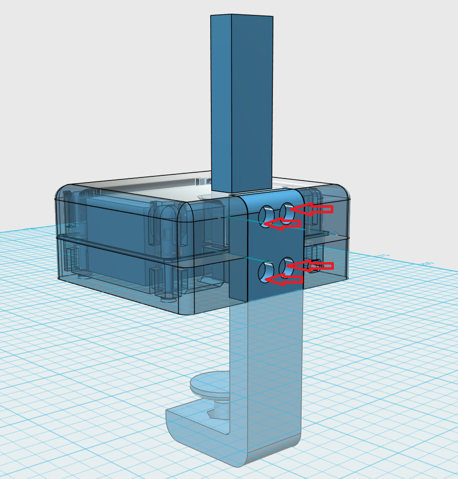
4Mark and Drill
Insert one of the flater ends of the arc into the 3d printed case and mark where the M4 bolts will be inserted (see below) and mark where the wood meets the top of the case (in pencil - to be removed later). Once marked, drill holes, starting small to make sure you dont destroy the wood.
![]()
-
5Add LEDs
Cut the LEDs to size roughly 2-3 cm above the mark of the top of the case. Stick the strip to the wood roughly in the middle.
-
6Wiring and Assembly (the awkward part)
It helps to have the wooden arc clamped sideways to a table for this part. Insert the LED wires into the top of the case and the wooden arc in too. Add the clamp piece to the back of the case and bolt together with the M4 bolts and nuts (inserted earlier). Put some heatshrink onto both the DC wires and solder the positive and negative to the positive and negative wires (respectively of course) of the LED driver (I tend to make little hooks/loops on each wire and wrap them a little around each other before soldering - a bit like this), cover with the exposed wires with the heatshrink and apply some heat to close it up.
Then feed in the AC cable (2 core) into the hole in the back of the case and solder it up in the same fashion as before (heatshrink on the wires first) to the AC end of the driver.
Screw the driver into the bottom of the case if necessary. Hotglue the AC wire inside the with a little slack just for some strain relief. Close it up, being careful to make sure the wires don't get caught. Then screw in the M3 bolts.
-
7Clamp
Print off a wingnut piece for an M8 bolt from your favourite 3D model repository. I used this one. Push the M8 both through the wingnut and tighten in the M8 nut into the bottom of the clamp piece (not too tight). Screw it up til it almost meets the end of the table and loosly screw on the bracing piece to reduce any marking on the bottom of the table (you can add some furniture felt pads for added protection if you want. Tighten it up until it has a grip on the table.
-
8Switch
Strip back the 2 core cable and cut and strip back the live wire according to the instructions on the in-line plug. I crimp, solder and hotglue for safety here and close it up quickly before the hotglue sets to keep it all together. Wire up a plug. Plug it in, turn it on and enjoy a brighter space!
Simple Curved LED Strip Lamp
As it got darker in winter I wanted a lamp that was simple and still DIY-chic and stylish.
Discussions
Become a Hackaday.io Member
Create an account to leave a comment. Already have an account? Log In.