-
1I/O Board
The I/O board is used to
- Enter the data input
- Enter the multiplexer selection
- Trigger the storing in the register
- Feed all data lines of select, data input, register and result to the display board
- Show all data line states (high/low) using LEDs
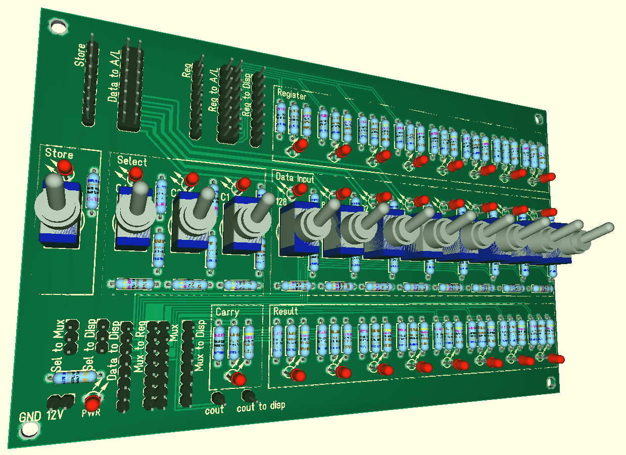
So this board is built of many switches, resistors, LED and connectors.
See also files:
- I_O_SCH.PDF
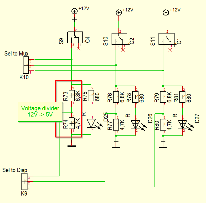
Below is the multiplexer selection circuit:
![]()
And a rendering of the whole board:
![]()
-
2Display board
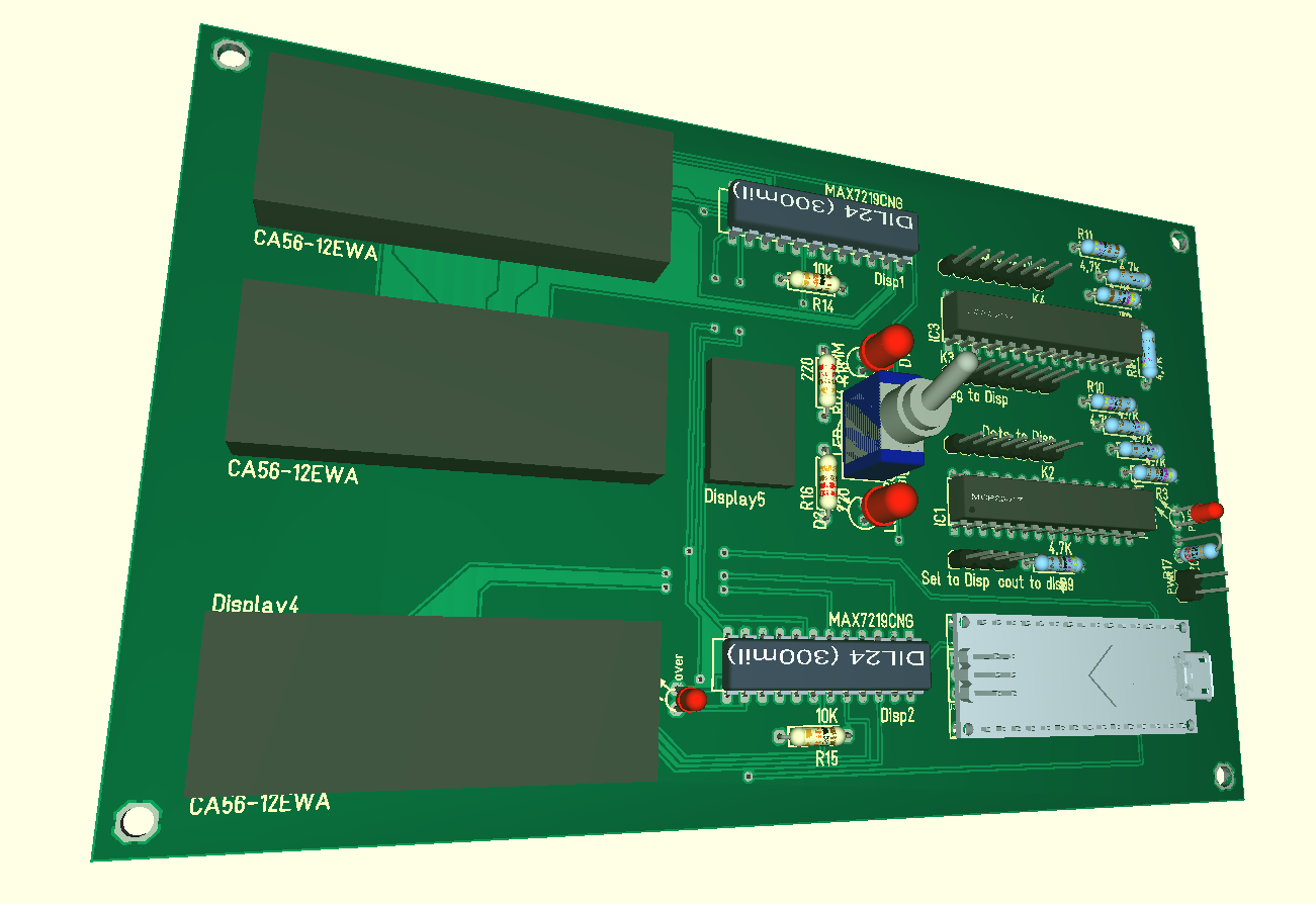
The display board helps in reading the data. It reads all data lines and displays them on 7 segment displays.
This is done with the help of an Arduino nano, two MCP23017 are used and for reading all the data lines and two MAX7219 for driving the displays.
See also files:
- disp_SCH.PDF
- display.ion
![]()
-
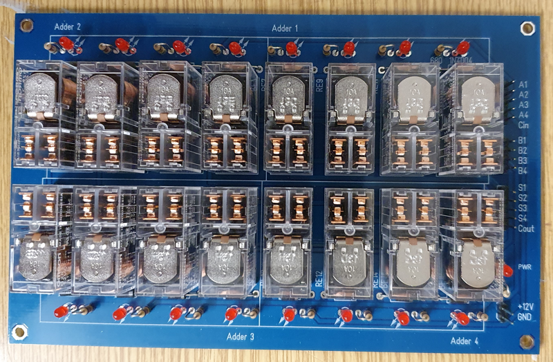
3Adder board
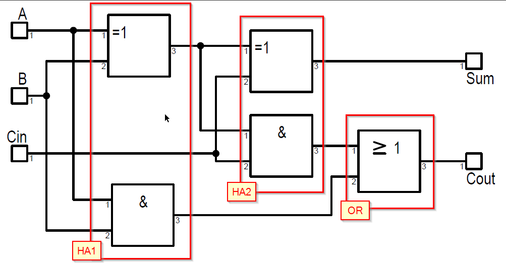
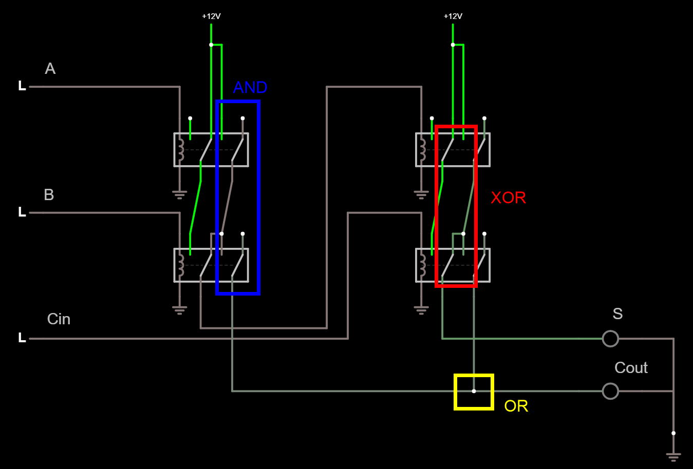
An adder is built of two half-adders:
![]() With DTDP relay this can be built as follows:
With DTDP relay this can be built as follows:![]()
See also files:
- add.circuit
- 4xFullAdder_SCH.PDF
![]()
-
4Logic board
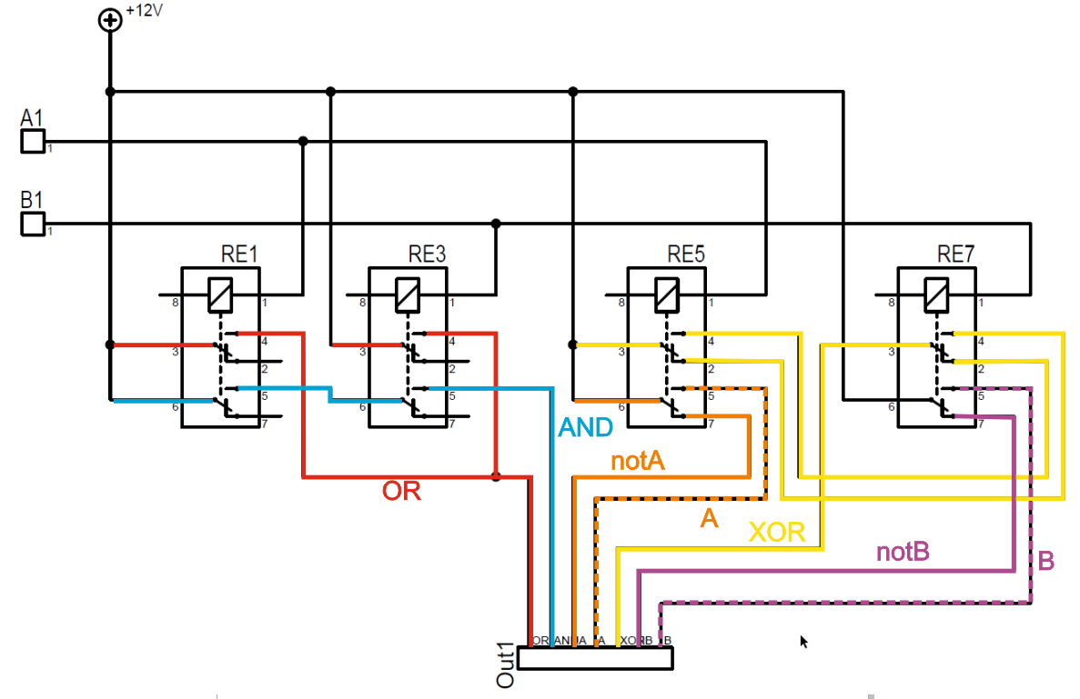
A simple Logic Unit. My intention was that it is easy to see how the logic works by seeing the relay switch on an off.
![]()
See also files:
- logic.circuit
- 4xLogic_SCH.PDF
-
5Register Board
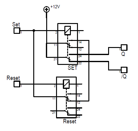
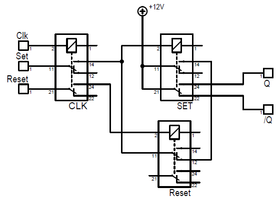
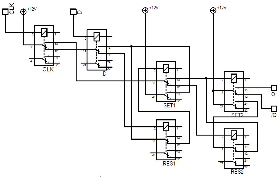
My small journey from RS Flip-Flop to a Raising Edge D Flip-Flop (GND is not shown in the pictures below - but it should be obvious where it is).
The simplest way to store a bit is an RS Flip Flop, it need 2 relay: 1 to hold the state and one to reset it.
![]()
The next step: Add a clock signal. As long as the clock is 'high' the state can be changed:
![]()
But computer data has no "set" and "restet" line only one line with 'high' and 'low'. Adding an additional data relay makes a level triggered D-Flip-Flop. The disadvantage is still, that, as long as the clock signal is 'high', changes get to the output. In my case, this would be bad, as the outputs are inputs to the logic, and the logic output is connected to the inputs of the register.
![]()
The solution is an edge triggered D-Flip-Flop. It adds an additional RS Flip-Flop. The 1st is always changed when the data signal changes. The 2nd 'offline' as the power to SET1(11) is disconnected.
When the clock switches to 'high', CLK switches off D(11) and enabled SET1(11). SET1 holds the state from exact before the CLK switch and therefore the 2nd FF takes over the state from the 1st one. Changes to the data line do not affect anything as D(11) is without power.
When the clock goes down, SET1(11) is again disconnected. The data is store.
![]()
I had to use smaller DPDT relay as there are six relay needed for one register.
See also files:
- dflip.circuit
- 4xD-EdgeTrig_SCH.PDF
To see, if my D-FF are working as expected, i wired them as a Ripple Counter:
-
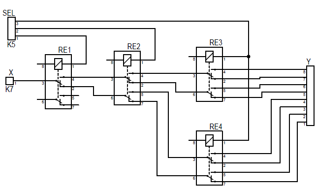
6Multiplexer Board
The multiplexer in my ALU ist strait forward: three control lines, driving 4 DPDT relay to select one out of eight inputs (or outputs).
![]()
-
7Finishing
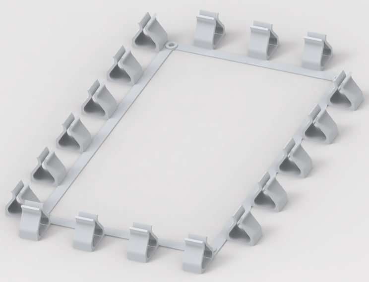
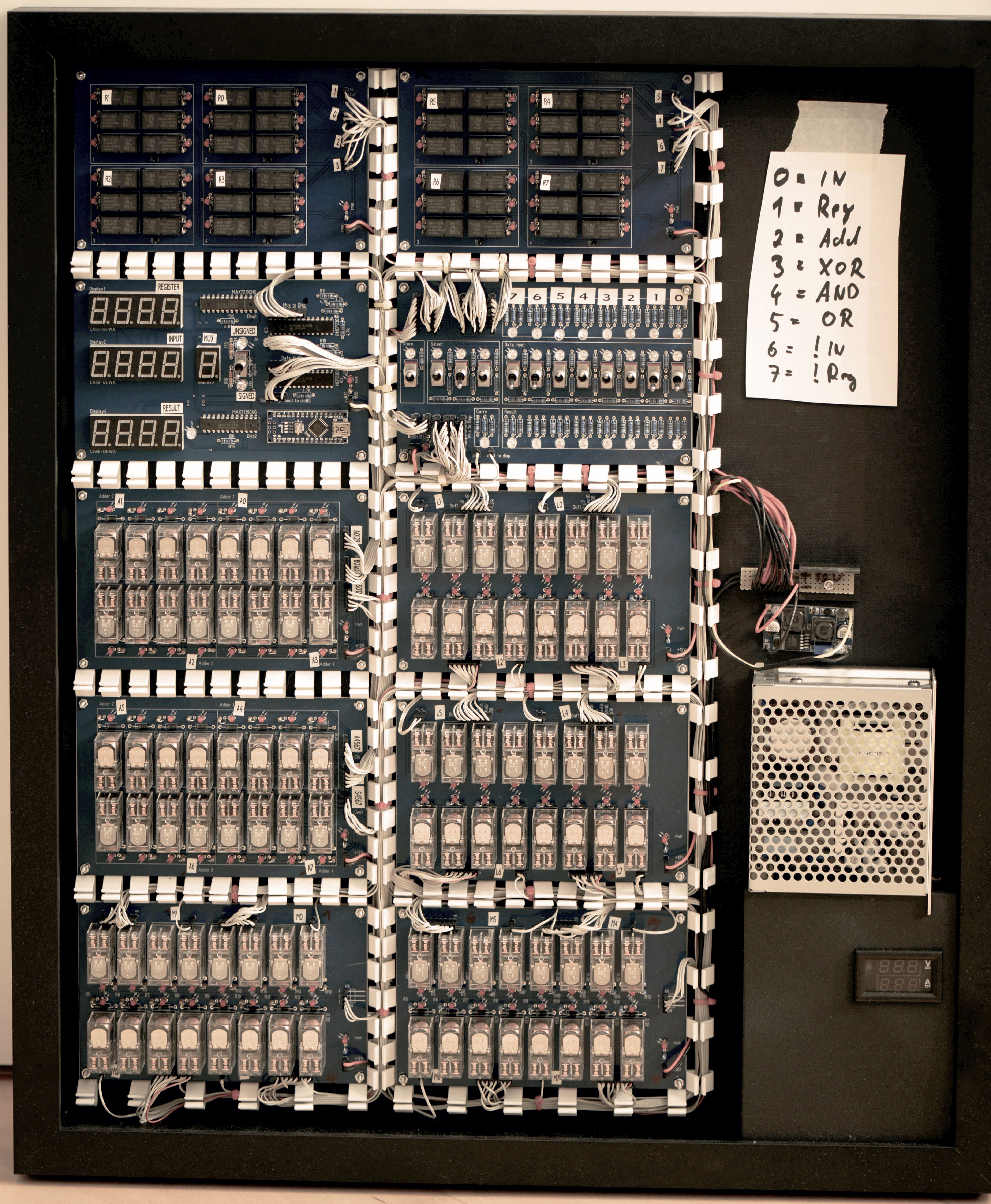
All boards are placed in a picture frame (object frame) with 3D printed cable routes. A 12V, 6A power supply and a buck converter for providing the 5V for the arduino are added.
![]()
 Christian
 With DTDP relay this can be built as follows:

Discussions
Become a Hackaday.io Member
Create an account to leave a comment. Already have an account? Log In.