 Kal
Kal-
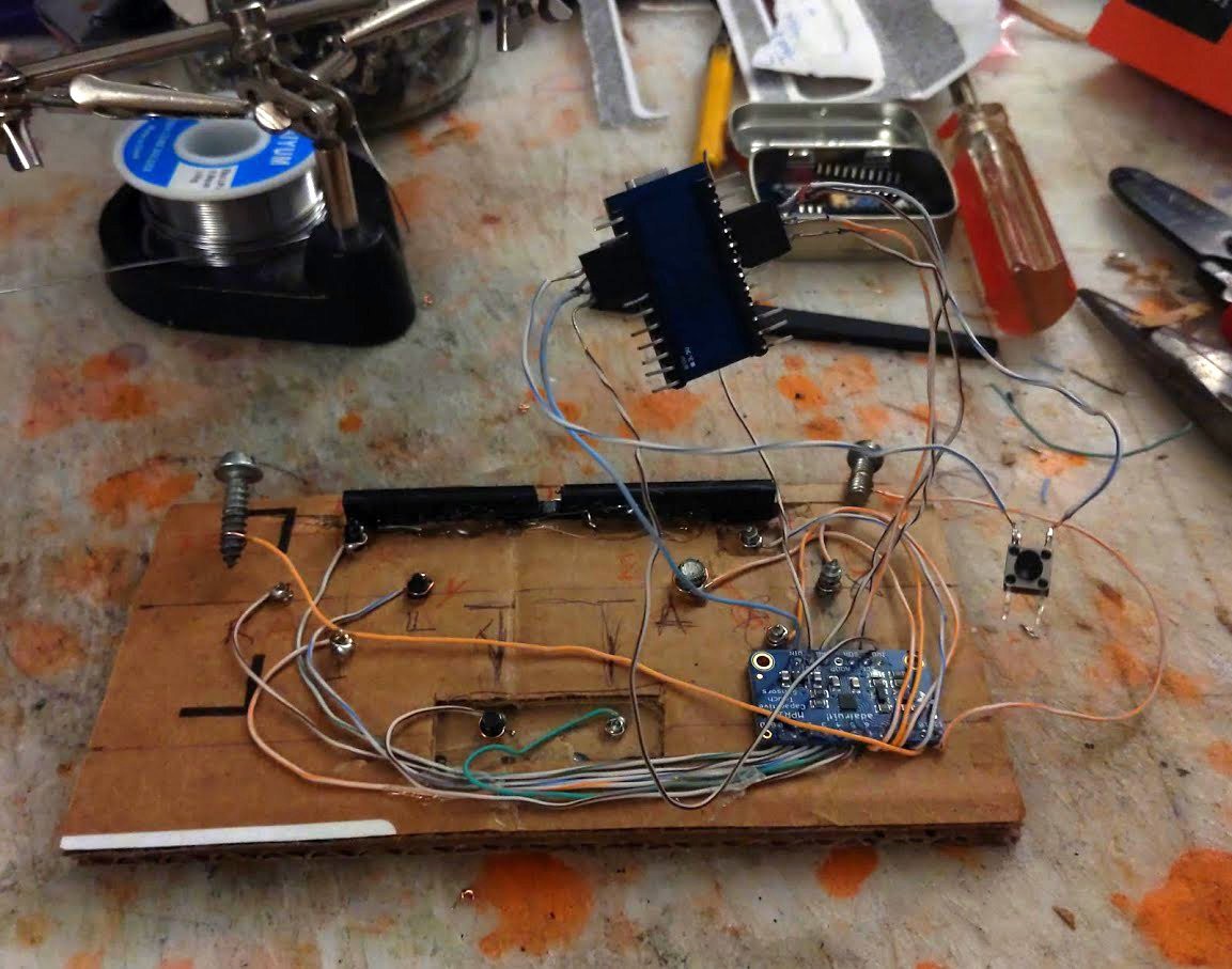
1Main Wiring
![]()
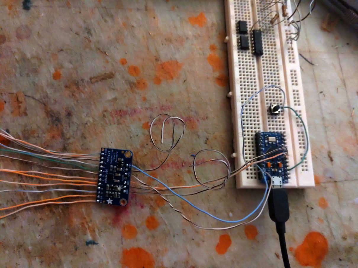
Connect MPR121 to arudino i2c and power. On a Micro this is pins 2&3 plus VCC and GND. Flash the arduino and make sure everything works as you like. Breaking out the RST pin to a tactile switch is probably unnecessary, i've had no problem re-flashing the 'ino since it's been put together, but it's a good idea.
/* Capacitive touch sensor gamepad * Intended for use with Adafruit's breakout and library for the MPR121 capacitive * sensor module and a USB-native Ardiuno (e.g. has a ATmega32U4). * * Much propers to Matthew Heironimus for his Joystick library. There are a bunch of * other libraries for the same purpose but i don't even care if they're better, his * is far and away the best documented i've found. * (https://github.com/MHeironimus/ArduinoJoystickLibrary/) */ /* ELECTRODE MAP: 11 10 7 0 8 6 3 2 9 1 4 5 MPR electrode #: SNES equiv.: associated Joystick.h control: 0 Y b4 1 A b1 2 B b2 3 X b3 4 select b6 5 start b7 6 D-right x+ 7 D-down y- 8 D-left x- 9 D-up y+ 10 Rb b5 11 Lb b4 ((Without making it pretend to be XInput there probably has to be some kind of reassignation by the end-user.)) */ const uint8_t Nu=7; const uint8_t Nd=9; const uint8_t Nl=8; const uint8_t Nr=6; const uint8_t Na=1; const uint8_t Nb=2; const uint8_t Nx=3; const uint8_t Ny=0; const uint8_t Nrb=10; const uint8_t Nlb=11; const uint8_t Nst=5; const uint8_t Nse=4; const uint8_t padDelay = 10; // i haven't noticed any difference with values 0~25, YMMV #include <Joystick.h> #include <Wire.h>; #include <Adafruit_MPR121.h> Adafruit_MPR121 cap = Adafruit_MPR121(); Joystick_ pad(JOYSTICK_DEFAULT_REPORT_ID,JOYSTICK_TYPE_GAMEPAD, 8, 0, // Button Count, Hat Switch Count true, true, false, // X and Y, but no Z Axis false, false, false, // No Rx, Ry, or Rz false, false, // No rudder or throttle false, false, false); // No accelerator, brake, or steering uint16_t padread; // to hold inputs for processing int8_t yInertia = 0; // for cleaning SCNODS, Simultaneous CardiNal Opposite Direction System int8_t xInertia = 0; void setup() { delay(10); cap.begin(0x5A); pad.begin(false); // "By default, all methods update the game controller state immediately." The whole rest of loop{} probably doesn't take as long as talking to the host 12 times. No, wait, prolly the library has delays built in pad.setXAxisRange(-1, 1); pad.setYAxisRange(-1, 1); } void loop() { padread = cap.touched(); // D-PAD: switch(((padread & (1<<Nu)) && (1<<Nu)) + ((padread & (1<<Nd)) && (1<<Nd))) { // how many of up and down are pressed? case 0: // none? do nothing, forget everything pad.setYAxis(0); yInertia = 0; break; case 1: // just one? if ((padread & (1<<Nu)) && (1<<Nu)) { // is it up? then go up pad.setYAxis(1); yInertia = 1; } else { // otherwise it's gotta be down, go down. pad.setYAxis(-1); yInertia = -1; } break; case 2: // both are pressed? if (yInertia == 0) {break;} // were we standing still? keep standing still if (yInertia > 0) { // if we were going up, keep going up pad.setYAxis(1); yInertia = 1; } else { // otherwise we must've been going down, go down pad.setYAxis(-1); yInertia = -1; } } // end y-axis, do the same for x-axis switch(((padread & (1<<Nl)) && (1<<Nl)) + ((padread & (1<<Nr)) && (1<<Nr))) { case 0: pad.setXAxis(0); xInertia = 0; break; case 1: if ((padread & (1<<Nr)) && (1<<Nr)) { pad.setXAxis(1); xInertia = 1; } else { pad.setXAxis(-1); xInertia = -1; } break; case 2: if (xInertia == 0) {break;} if (xInertia > 0) { pad.setXAxis(1); xInertia = 1; } else { pad.setXAxis(-1); xInertia = -1; } } // end of x-axis // END OF D-PAD // non-hysterical buttons: pad.setButton(0, ((padread & (1<<Na)) && (1<<Na))); // a pad.setButton(1, ((padread & (1<<Nb)) && (1<<Nb))); // b pad.setButton(2, ((padread & (1<<Nx)) && (1<<Nx))); // x pad.setButton(3, ((padread & (1<<Ny)) && (1<<Ny))); // y pad.setButton(4, ((padread & (1<<Nlb)) && (1<<Nlb))); // LB pad.setButton(5, ((padread & (1<<Nrb)) && (1<<Nrb))); // RB pad.setButton(6, ((padread & (1<<Nse)) && (1<<Nse))); // select/back pad.setButton(7, ((padread & (1<<Nst)) && (1<<Nst))); // start pad.sendState(); delay(padDelay); } -
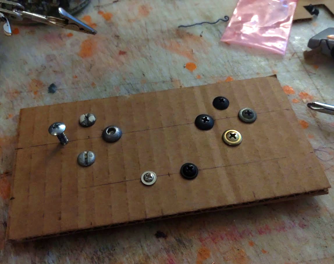
2Build the front face
Map out one piece of cardboard with placements for the screws
![]()
-
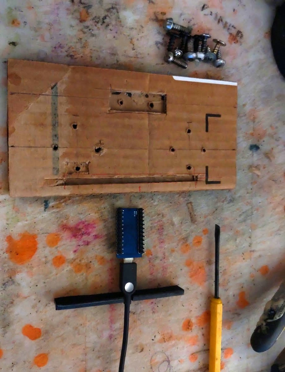
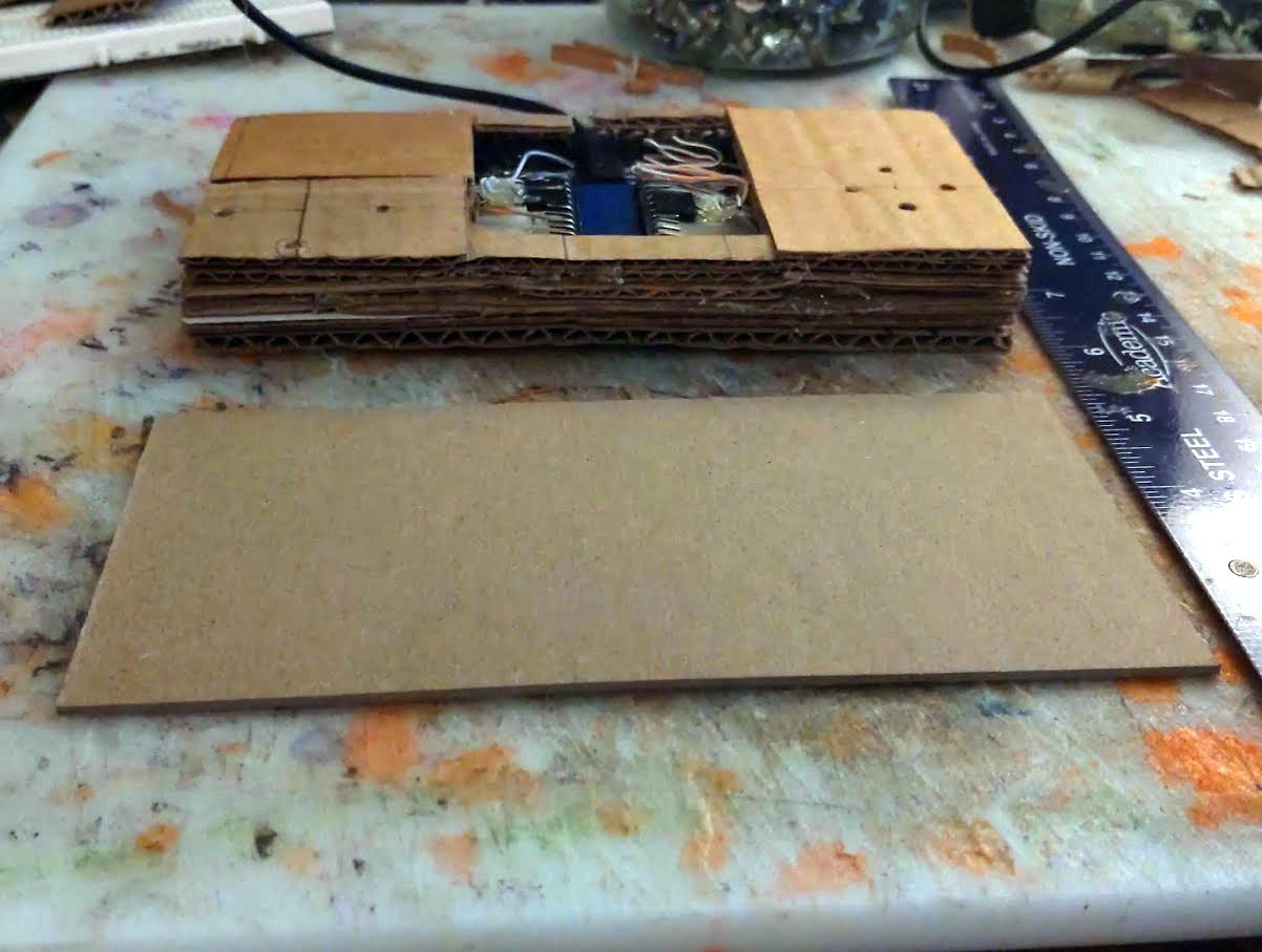
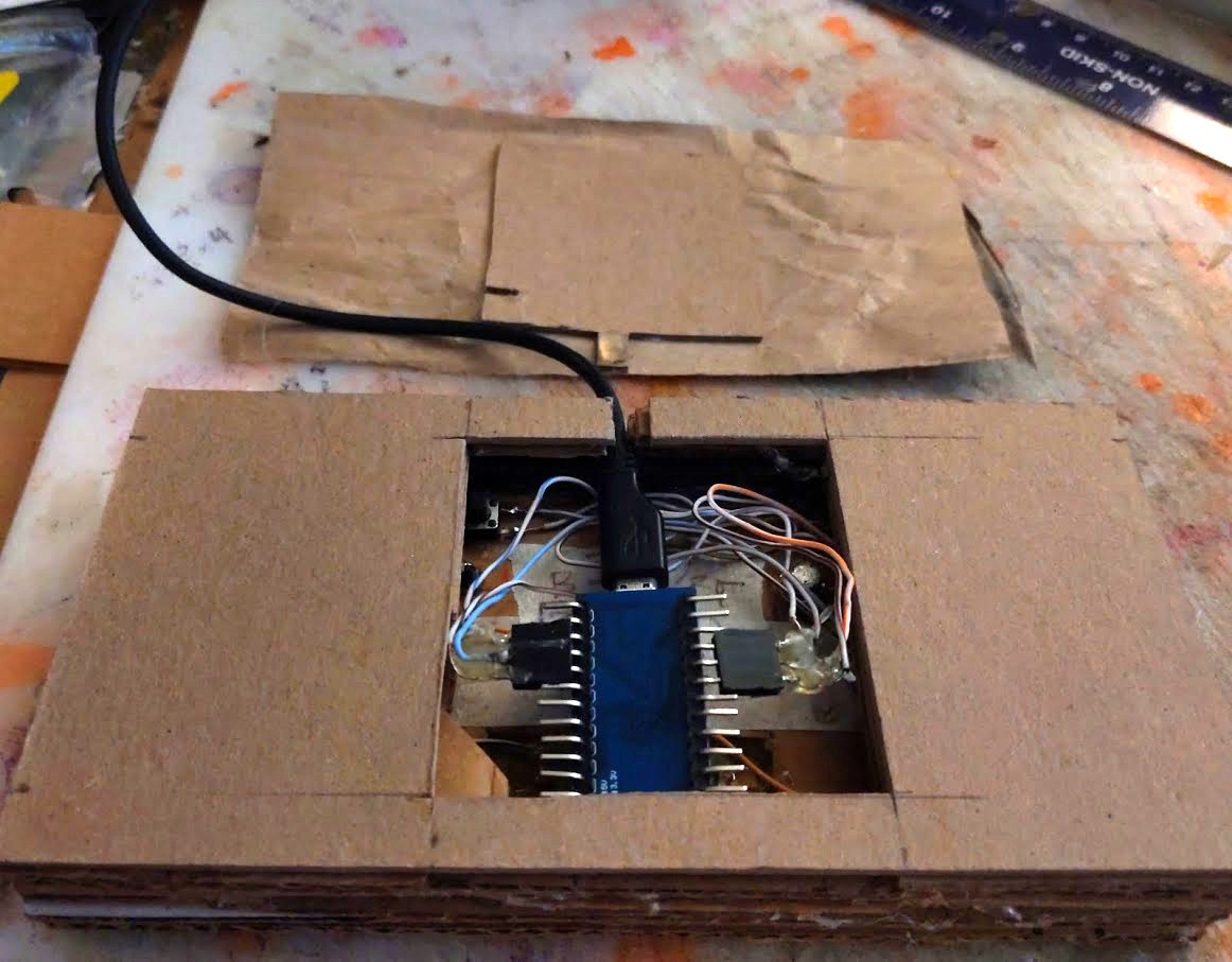
3Strain relief
![]()
Cut a notch in a piece of plastic to hold the USB line from pulling out and cut a slot into the cardboard face to hold that. I could've just glued the arduino and the cable to the cardboard but this feels like a better solution.
-
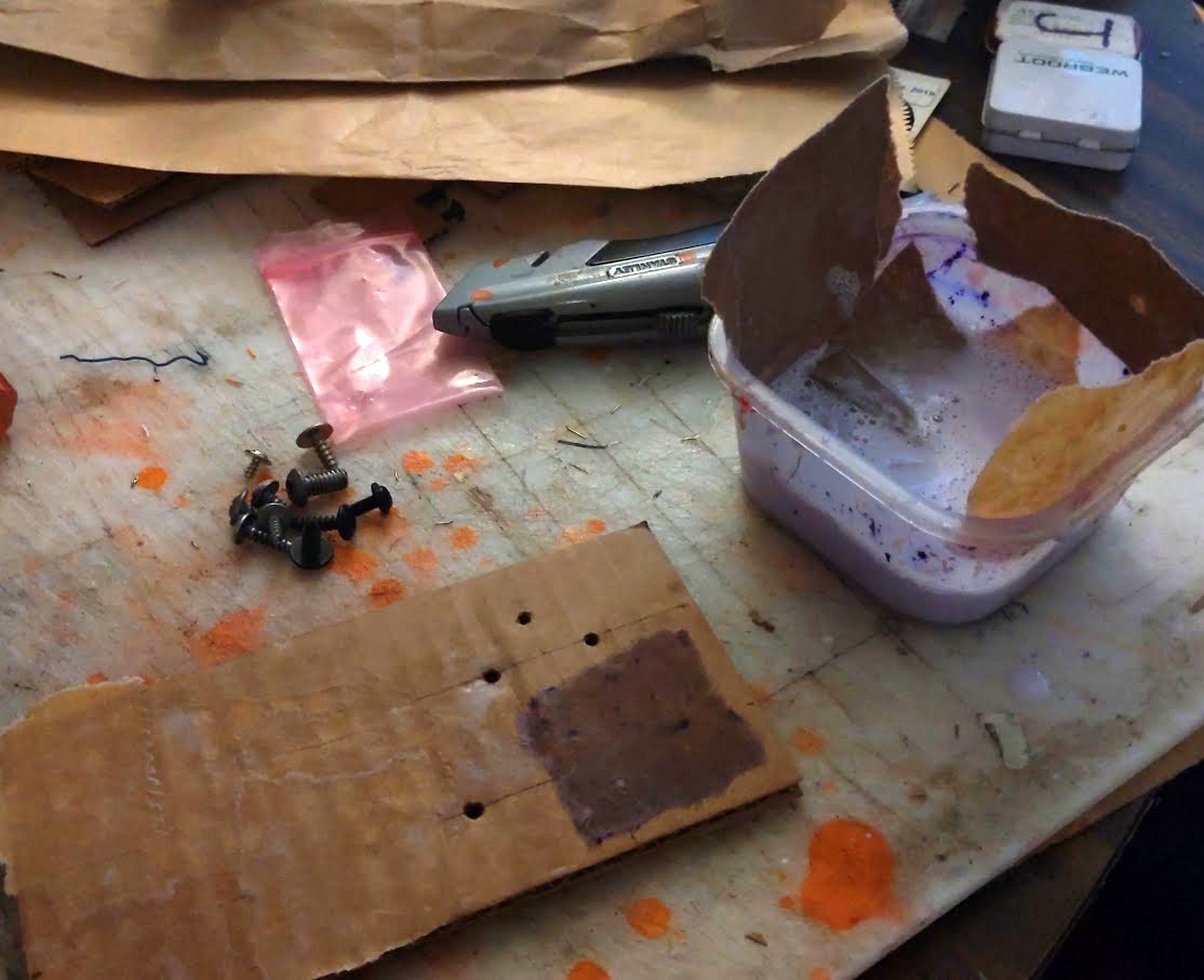
4Cladding
![]()
Soak some brown paper in diluted glue and cover the face for aesthetics. Skip this step if you're not worried about looks. Alternately just paint everything when you're done, my experience suggests the touchpoints will work flawlessly through a coat or two of paint.
-
5Connect touchpoints
![]()
Solder wire to the MPR121 electrode pins and connect those wires to the screws. Wrapping bare copper around the screw threads should be enough contact to work reliably but i did solder the wires to themselves as well. Soldering the wires to the screws is a pain in the ass in my experience, i didn't worry too much about that. Hot glue holds everything in place.
-
6Finish construction
![]()
Glue additional layers of cardboard until you reach the desired thickness. For the back i used a piece of heavy cardstock and cut out a window, then glued that to a piece of brown paper and glued the paper to the rest of the back. This way it'd be easy to replace the arudino or connect anything to unused pins. Then finish covering the thing in brown paper, completing the look.
![]()
Capacitive Gamepad
A sculptural USB gamepad with capacitive touchpoints as inputs
Discussions
Become a Hackaday.io Member
Create an account to leave a comment. Already have an account? Log In.