 Open Green Energy
-
11Using Heat Set Inserts
![]()
![]()
![]()
![]()
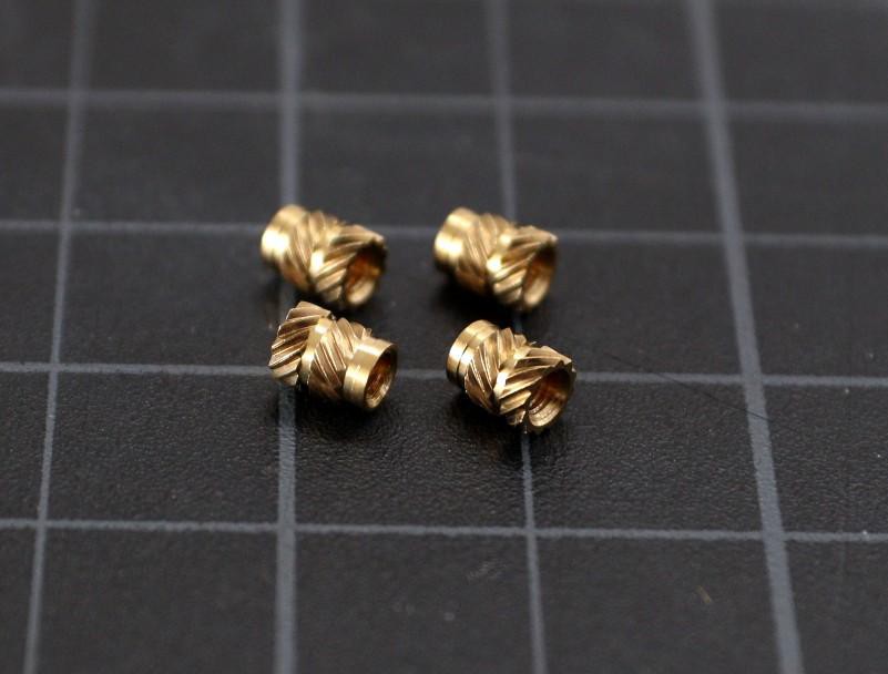
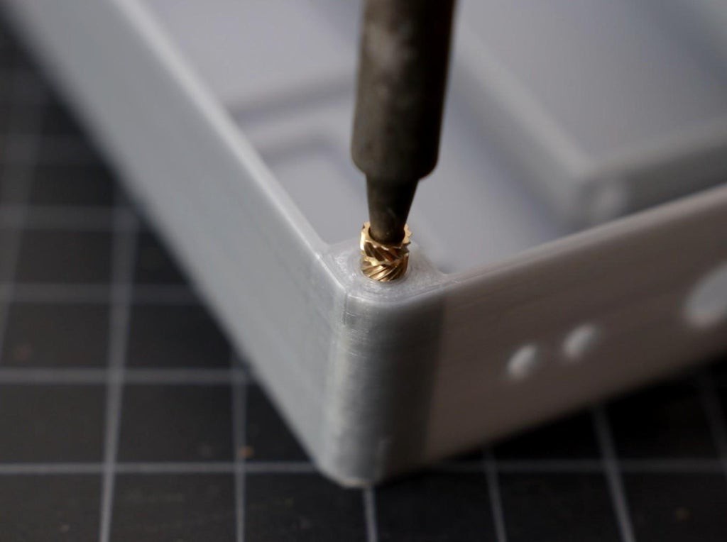
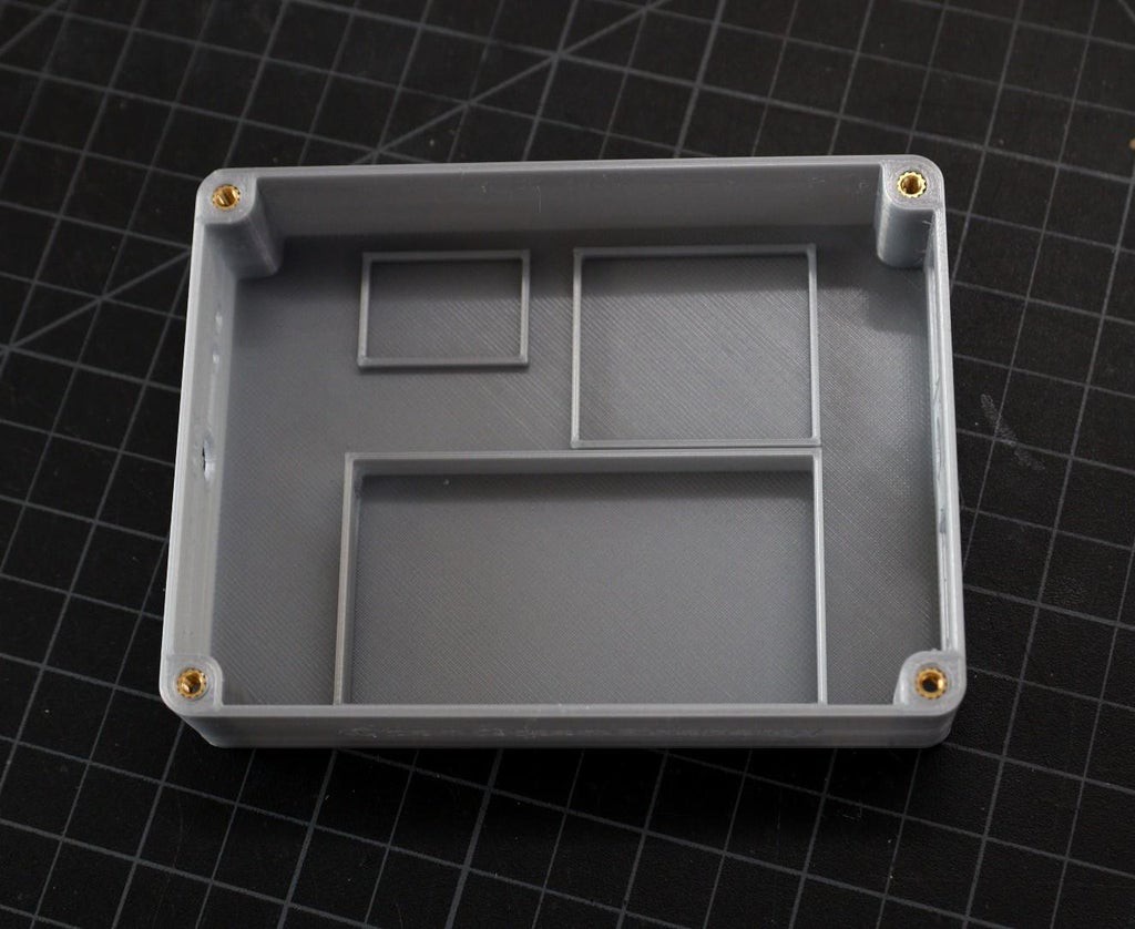
Threaded brass inserts can be a great way to add longevity to our 3D printed enclosures because we will 4 screws at the 4 corners to secure the top lid. Threaded inserts are commonly brass with a pre-formed thread within them.
Allow your soldering iron to heat for 3-5 minutes before installing inserts. This will ensure that you have to use the least amount of force to install inserts. The tip of the iron heats up the brass and softens the plastic. Pressing down pushes the insert into the part and once it cools down, it’s locked in place.
-
12Connect the Input DC Jack to TP5100
![]()
![]()
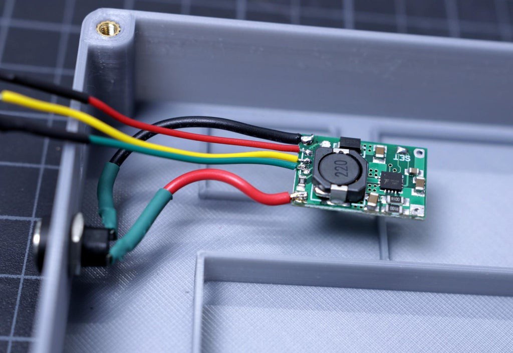
Mount the 5.5mm female DC jack to the 3d printed enclosure slot.
Then solder the terminal wires of the DC jack to the input terminal of the TP5100 as shown above. The red wire is positive and the black wire is negative.
-
13Install the Components
![]()
![]()
![]()
![]()
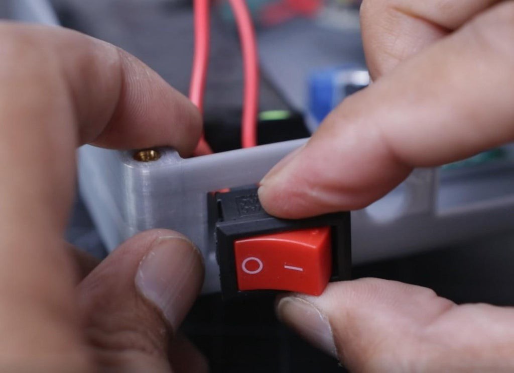
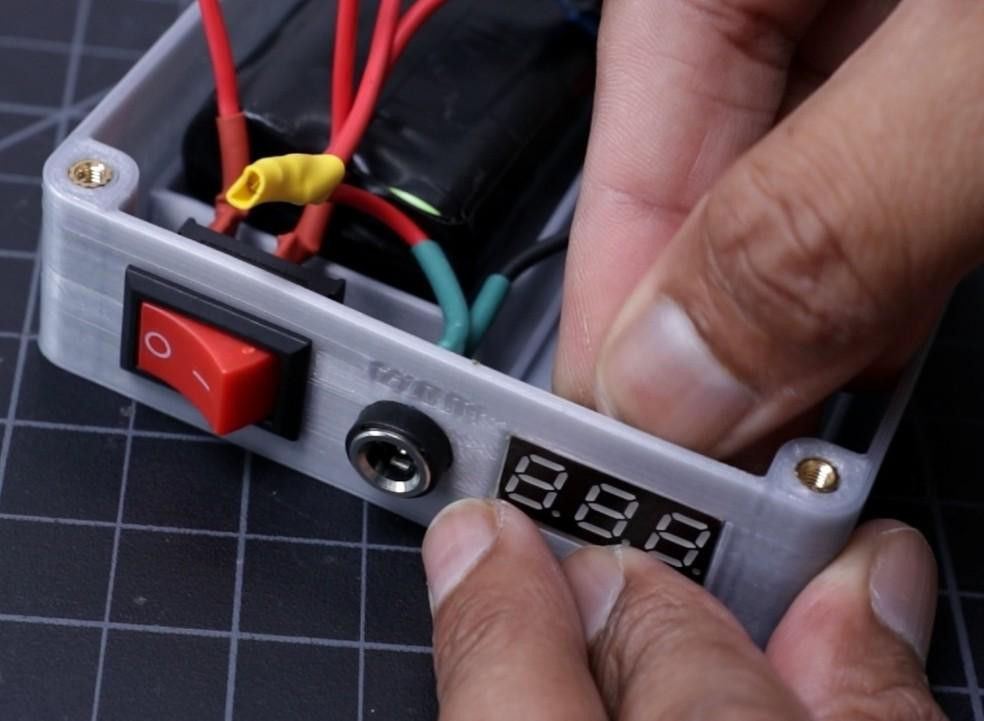
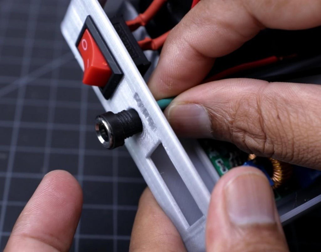
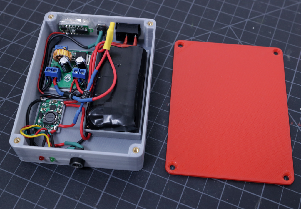
Install the DC Jacks, Rocker Switch, and Voltmeter display unit to the slot provided in the 3D printed enclosure.
Apply hot glue to mount the charging status LEDs and Voltmeter.
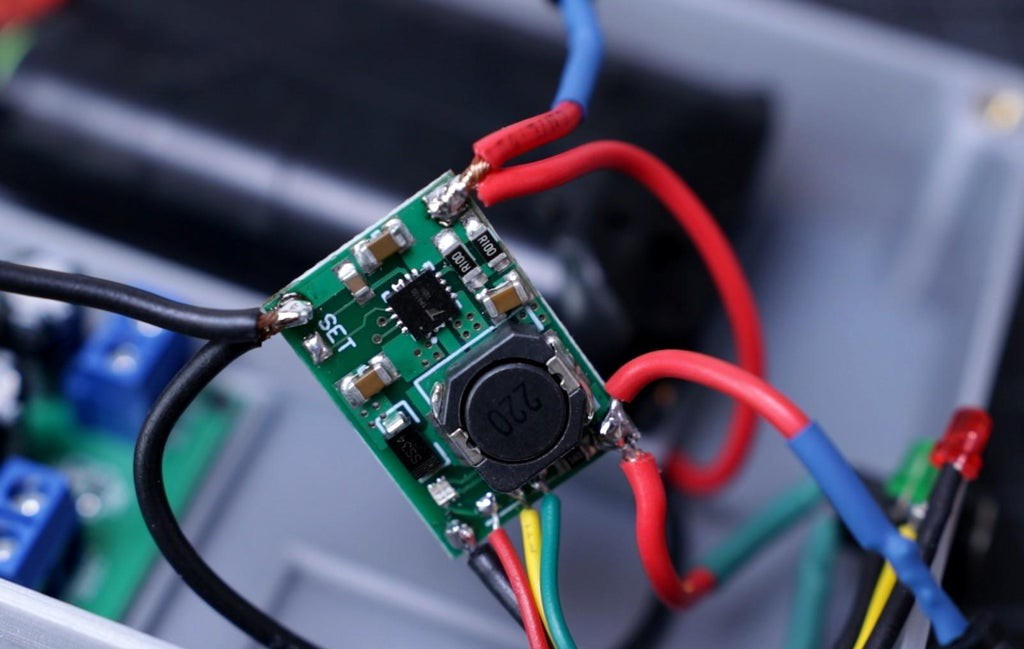
Similarly mount the TP5100 charging board, battery pack, and the LM2587 boost converter by using hot glue.
Note: Mount the charging board, battery pack, and the boost converter only after completion of all the connections as per the schematic.
-
14Make the Circuit
![]()
![]()
![]()
![]()
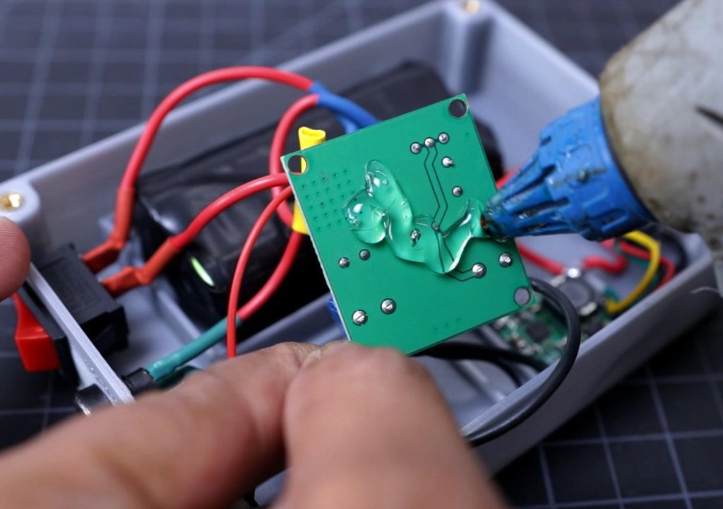
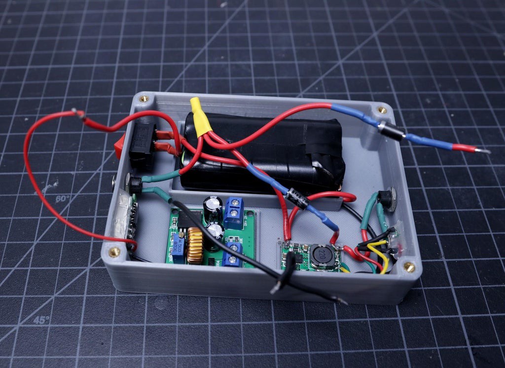
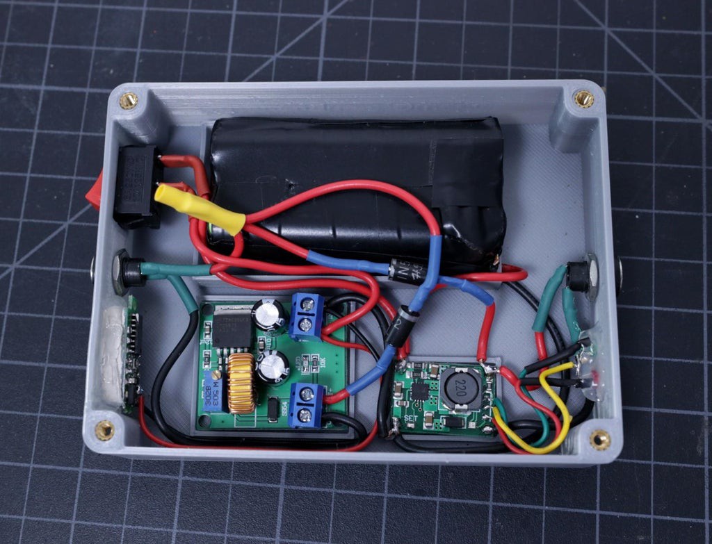
Solder one diode positive terminal to the positive terminal of the TP5100 and the negative terminal to the positive terminal of the Output DC Jack. Similarly the second diode positive terminal to the boost converter Out+ terminal and negative terminal to the DC jack positive terminal. To avoid any damages to connecting two thick wires to the DC jack terminal, I made a junction point ( covered by yellow heat-shrink tubing ).
TP5100 positive terminal is connected to the positive terminal of the battery pack and one terminal of the rocker switch. And the negative terminal is connected to the boost converter IN- and battery pack negative terminal. The other end of the rocker switch is connected to the boost converter IN+.
Voltmeter display positive is connected to boost converter IN+ and the negative terminal is connected to the IN-.
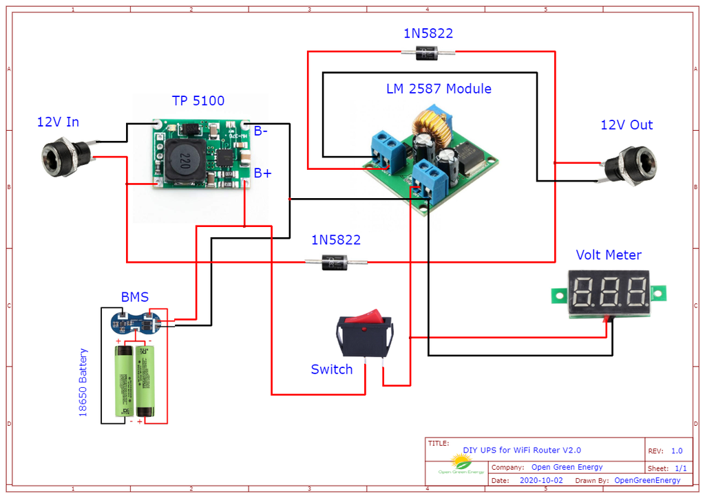
I will recommend taking a printout of the attached schematic diagram and make the circuit as per it. Before connecting the input DC adapter, double-check all the connections.
Note: Red and black wire in the schematic represent positive and negative respectively.
-
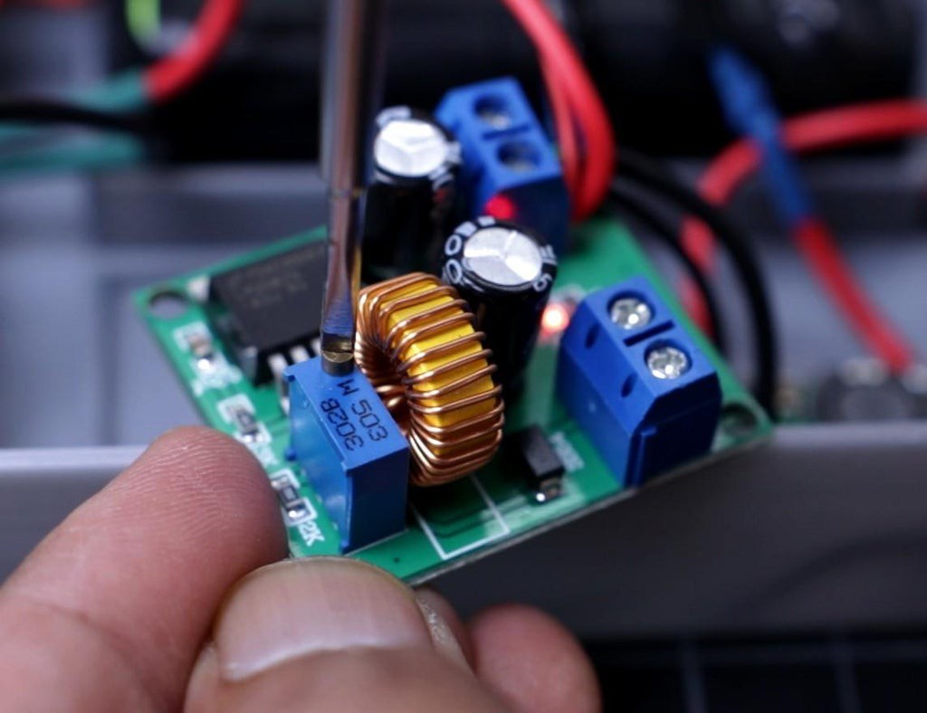
15Set the Boost Converter Output
![]()
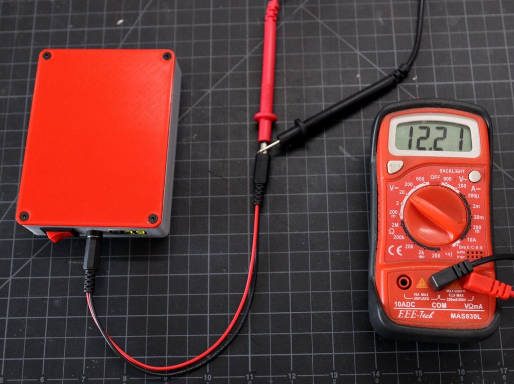
After connecting the wires to the Input and output screw terminal of the Boost Converter, you have to set the output voltage.
Place your multimeter prove at the output terminal and adjust the trim pot until you get 12V.
-
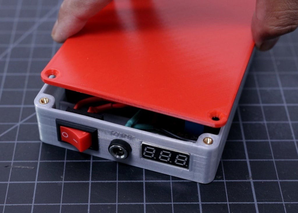
16Close the Top Lid
![]()
![]()
![]()
![]()
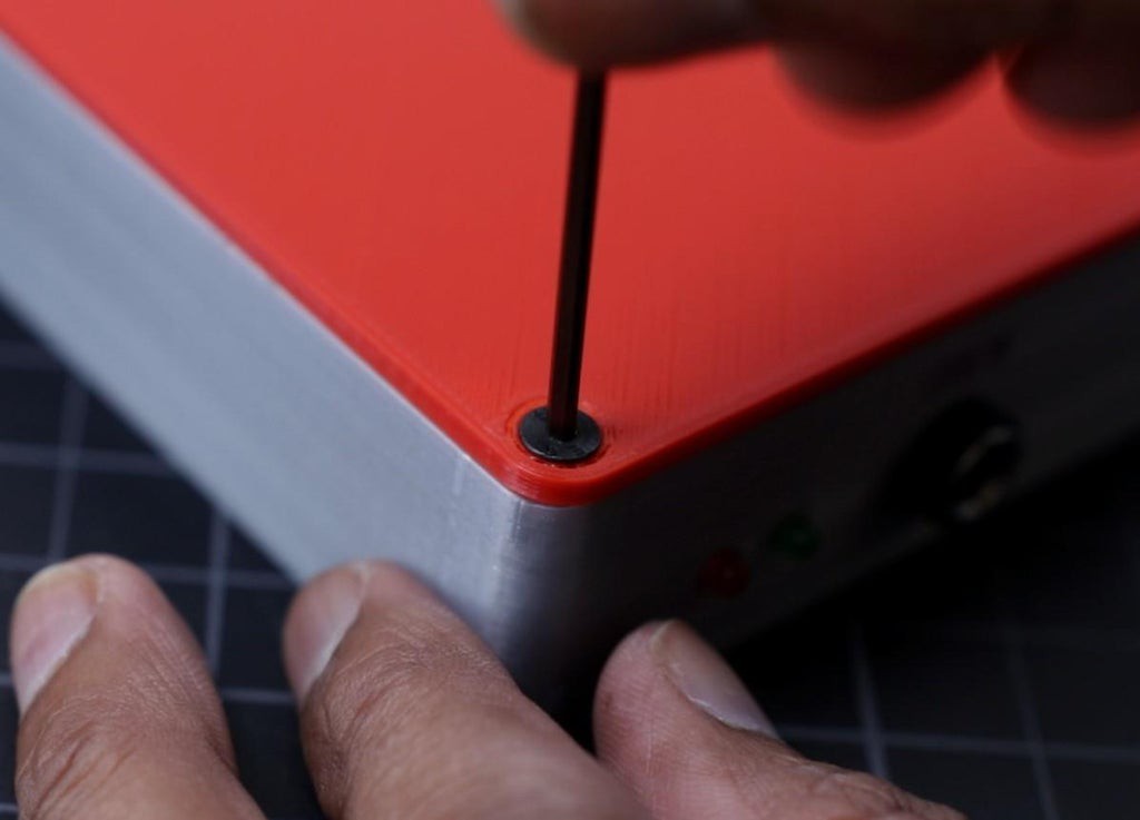
Finally, place the top lid and secure the 4 screws at the corners.
I have used 3M x 8mm screws to secure the lid. the counter sinkholes in the enclosure fit perfectly to the screw heads. I used the Allen key to tighten the screws.
Never overtighten the screws, otherwise, the enclosure may cracks or breaks.
-
17Final Testing
![]()
![]()
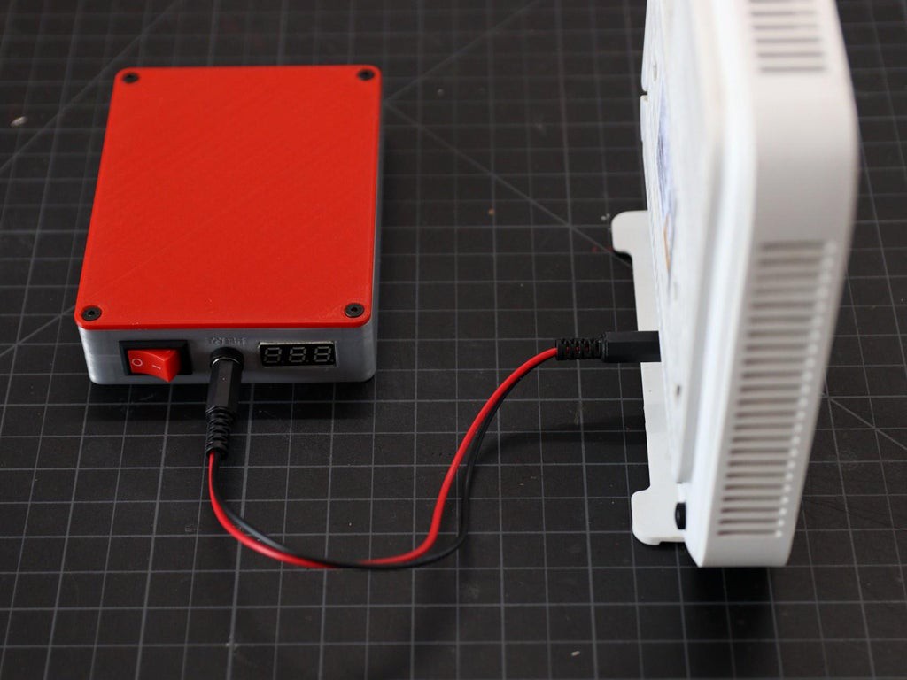
The last step is to test the UPS, plug in the 12V adapter jack to the input jack. Now you will notice the red will glow, it indicates the battery is charging. You can always check the exact battery voltage from the voltmeter display on the output side.
Once the battery is fully charged, plug in the DC jack cable prepared in the earlier step into the female jack at the output. The other end of the cable will connect to the Router power input port.
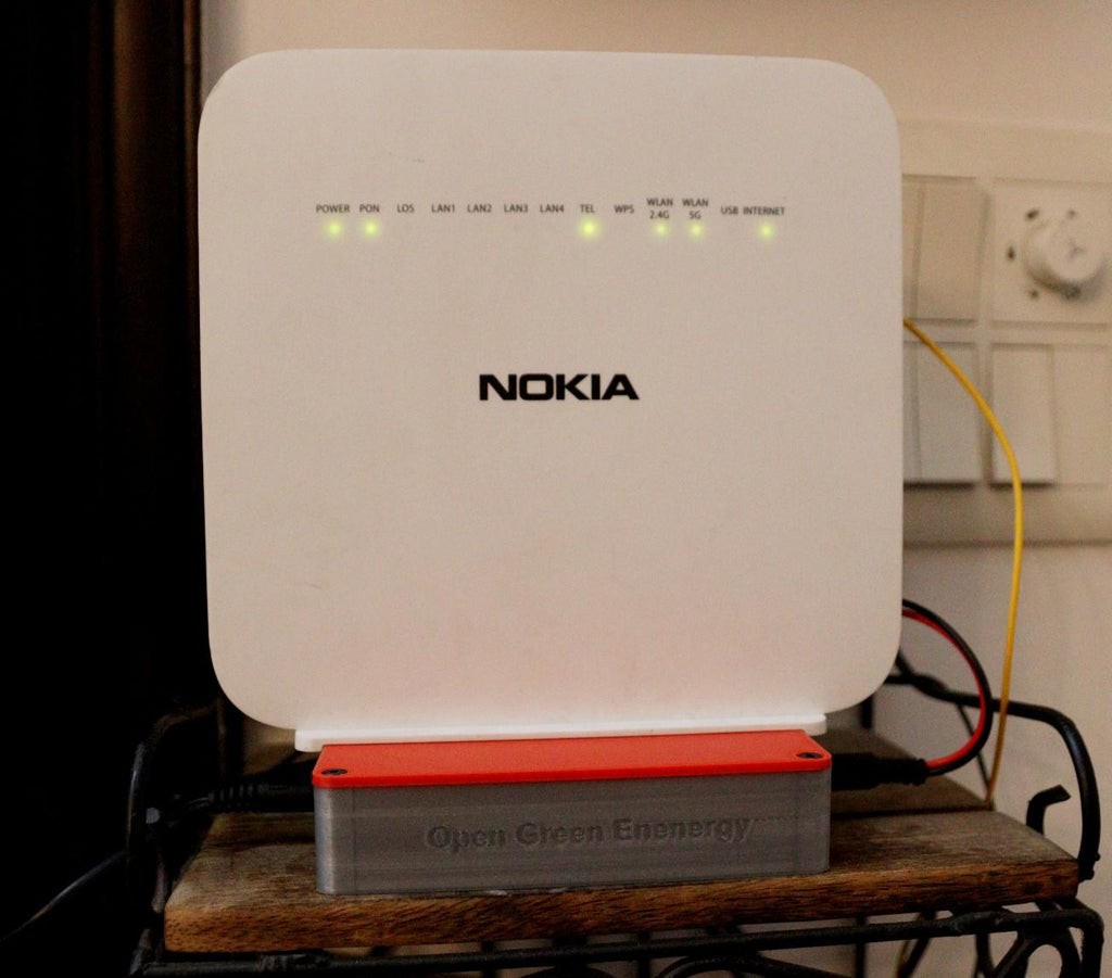
Turn the switch ON, the router status LED starts to glow and after a few minutes, your router is ready for providing internet service. At this stage, you can unplug the input DC adapter, you will notice the router is still working flawlessly. You can check the backup time in this condition. I have checked with my router ( 12V / 1.5A ), the backup time is more than 2 Hrs.
DIY Mini UPS for WiFi Router
A DIY uninterrupted power supply that can power up a WiFi-Router/Modem


Discussions
Become a Hackaday.io Member
Create an account to leave a comment. Already have an account? Log In.