 Open Green Energy
-
1Prepare the Battery Pack:
![]()
![]()
![]()
![]()
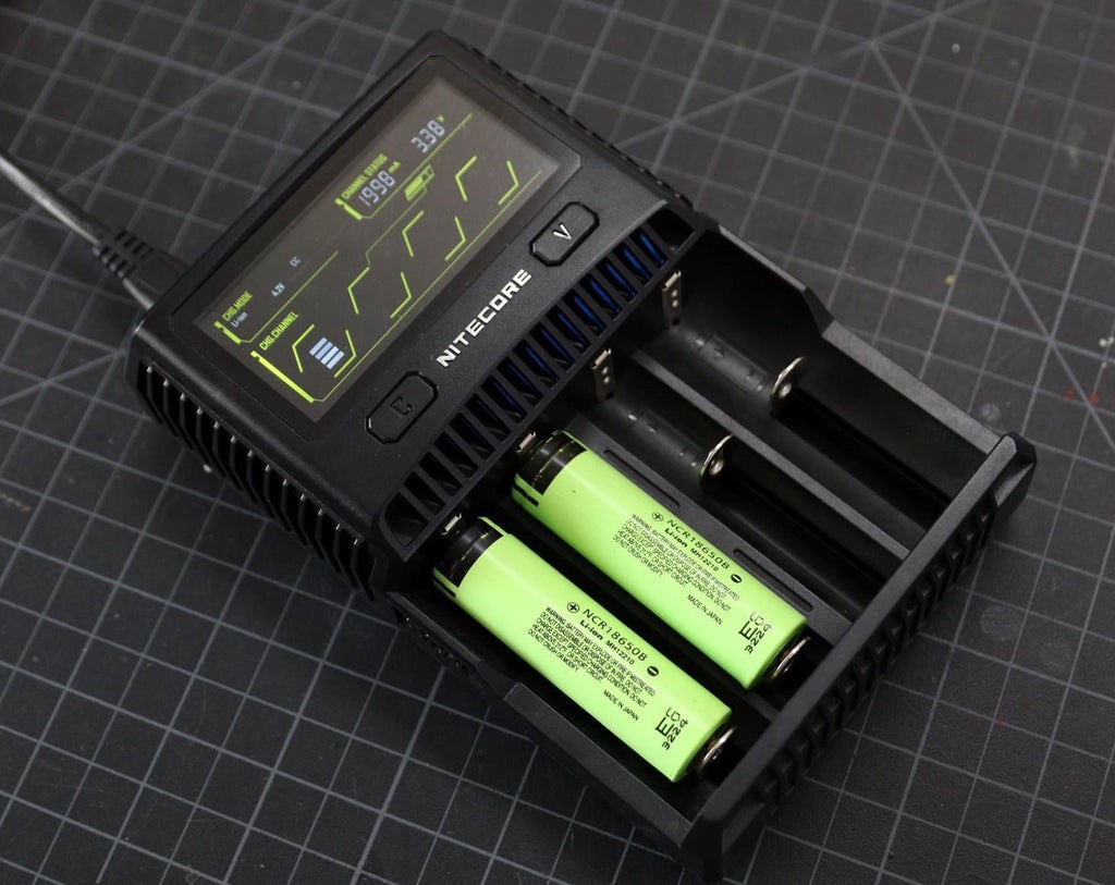
First, charge the two 18650 batteries by using a good charger. Here I am using a NITECORE charger.
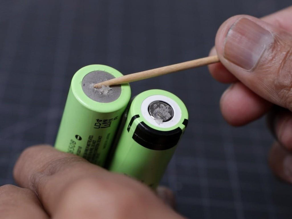
Clean the terminal of the 18650 battery by using a clean cloth, if required you can use fine sandpaper.
Apply a small amount of soldering flux in all four terminals.
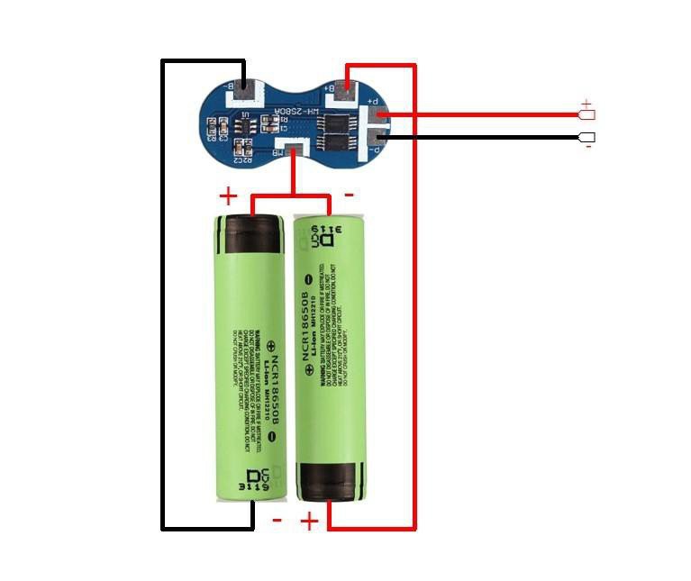
Then make a series connection between the two batteries. Keep two batteries side by side, one battery positive terminal shall face towards the negative terminal of another battery. You can see the above picture for your reference. Then Join them together by using 3M double-sided tape.
Solder a thick wire ( 20 AWG ) in the midpoint of the two batteries ( junction of the positive and negative terminal )
Solder a black wire to the negative terminal of the first battery and red wire to the positive terminal of the second battery.
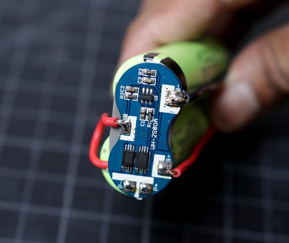
Before soldering the wires to the BMS board, tin all the soldering pads for the good soldering joint.
The red wire from the middle point of the battery pack is connected to the BMS MB terminal.
The red wire is connected to BMS B+ and the black wire is connected to B-.
At last, connect a red wire to the BMS P+ terminal and a black wire to the BMS P- terminal. These two terminals will be used for charging or discharging the battery pack.
-
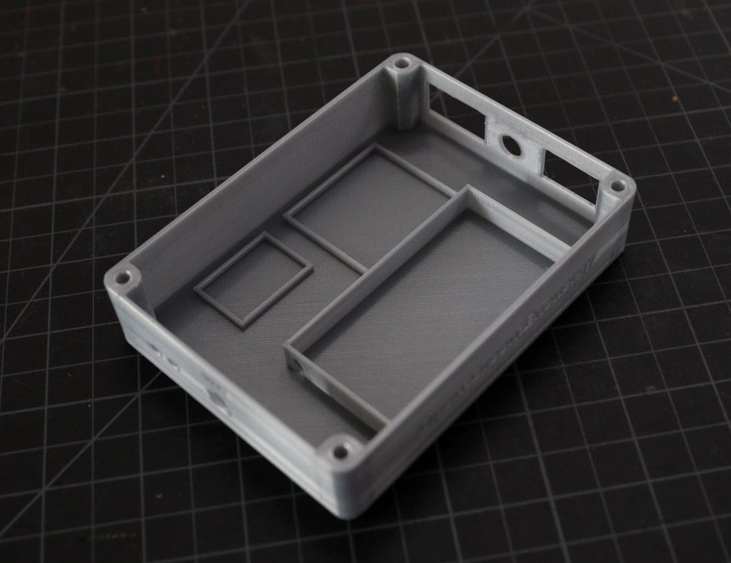
2Designing 3D Printed Enclosure
![]()
![]()
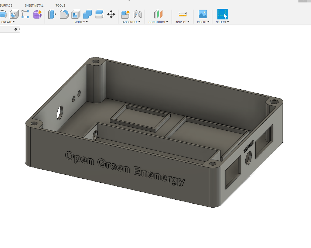
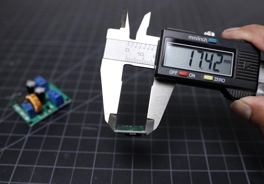
To give a nice commercial product look, I designed an enclosure for this project. I used Autodesk Fusion 360 to design the enclosure. The dimensions of all the components are measured by a vernier caliper then the same were considered during the design.
The enclosure has two parts:
1. Main Body
2. Cover Lid
The Main Body is basically designed to fit all the components including the battery. The Cover lid is to cover up the main body opening.
-
3Prepare the TP5100 to Charge 2S Battery Pack
![]()
![]()
![]()
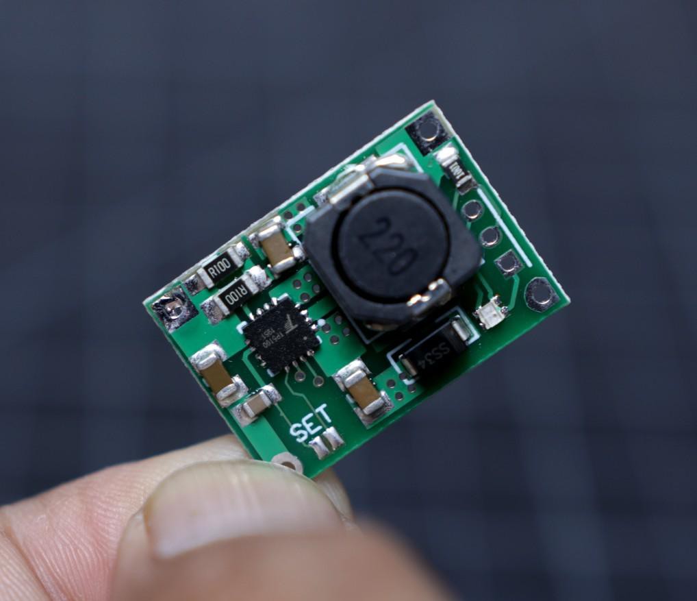
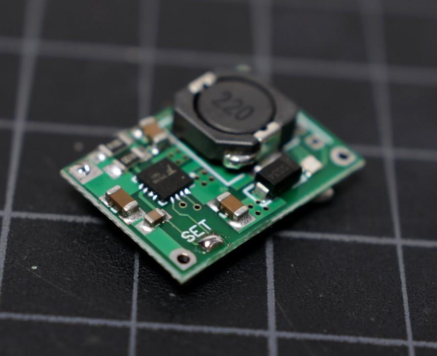
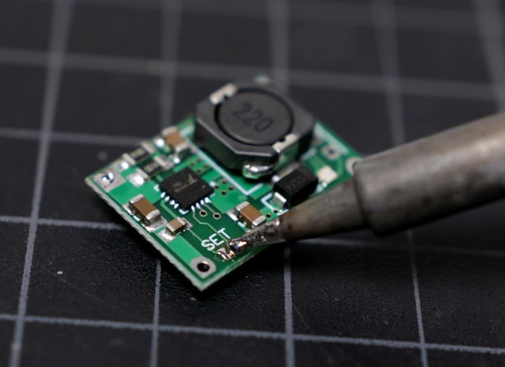
The TP5100 is a charging management module suitable for charging a single/double lithium battery (4.2V / 8.4V).
The default setting of the board is suitable for charging a single cell ( 4.2V ) lithium battery. To set it for double cell ( 8.4V) charging, you have to short the soldering pad named as " SET ".
Apply a small amount of solder to your soldering iron tip and then short the two soldering pad.
-
4Prepare the Charging Status LEDs
![]()
![]()
![]()
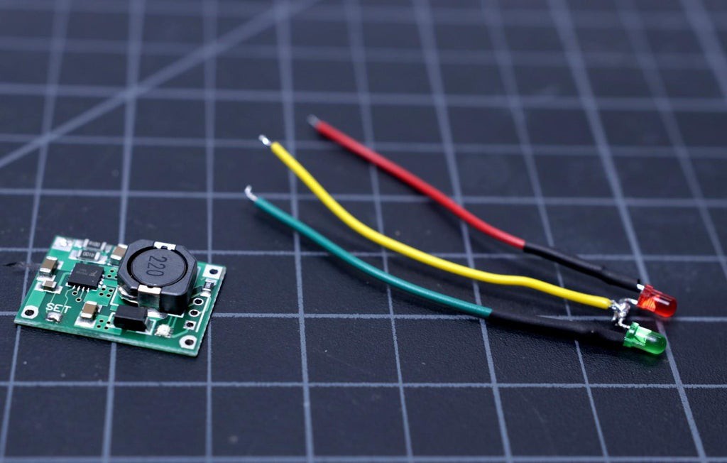
The TP5100 charging module has one onboard bi-color LED ( red and blue ) to indicate the charging status. But the objective is that the led should be visible to the outside of the enclosure. We are fortunate that the module also has some pads for connecting an external bi-color LED (common anode) next to the input. You can use a common anode bi-color LED or use two LEDs ( Red and Green)
I have used two 3mm LEDs instead of a common anode bi-color LED.
First, bend the two anodes of LED at the right angle as shown in the above picture. Then trim the legs as per the desired length and solder them together.
Solder a red wire to the red LED cathode, green wire to the green LED cathode and a yellow wire to the common anode. I have used 24AWG hookup wires to the LED legs. For solid connections and protection to the soldering joints, apply a heat-shrink tube.
At last, solder the terminal wires to the 3 soldering pads of the charging module TP5100.
-
5Prepare the DC Jacks
![]()
![]()
![]()
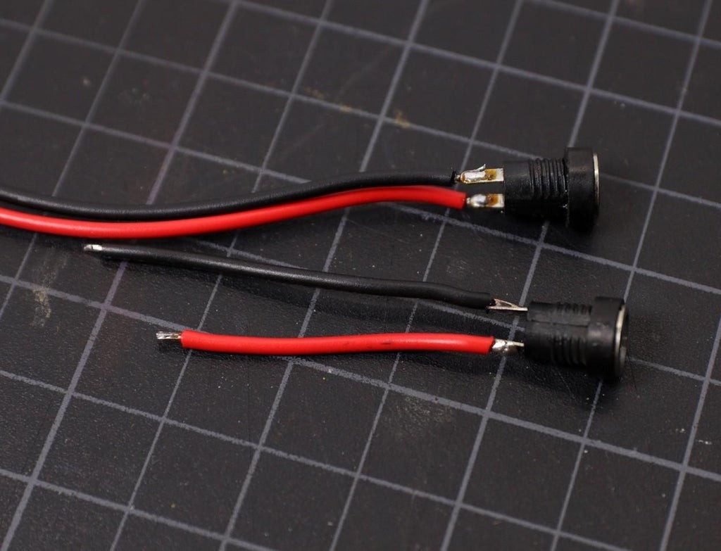
The DC jacks are used for supplying power to the UPS ( 12V input ) from a DC adapter and delivering power to the Router ( 12V Output ).
Clean the terminals of the DC Jacks and then apply a small amount of soldering flux to them. The main purpose of the flux is to prepare the metal surfaces for soldering by cleaning and removing any oxides and impurities. Oxides are formed when metal is exposed to air and may prevent the formation of good solder joints.
Before soldering the terminal wires, tin them by applying a small amount of solder.
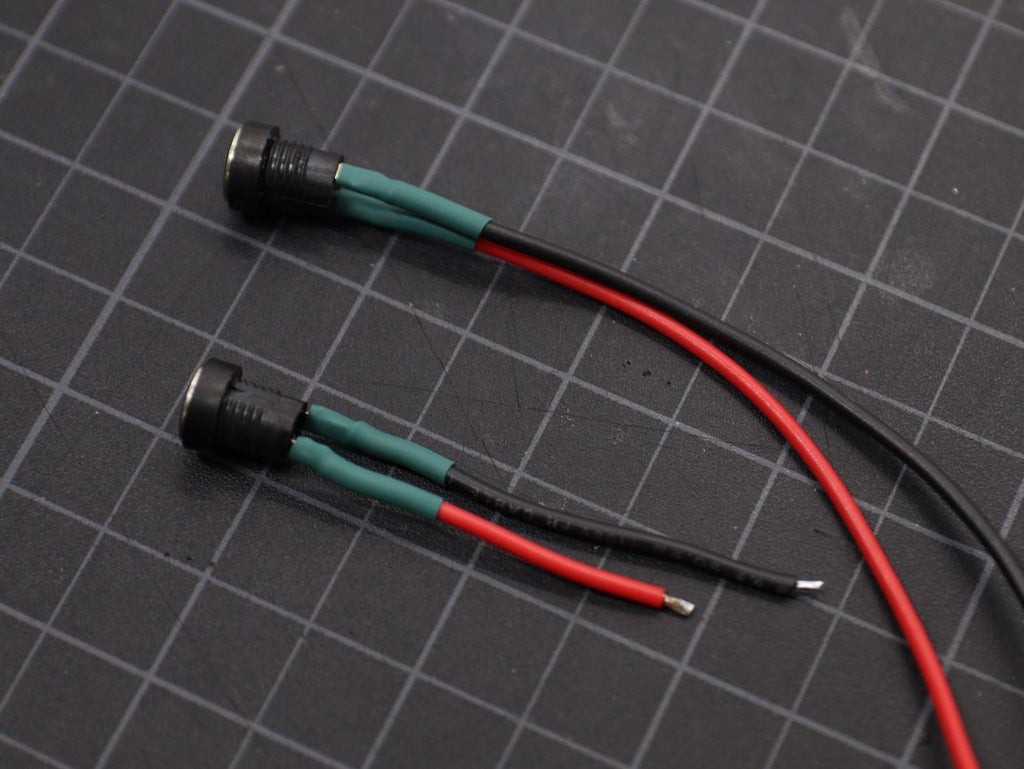
Solder a red wire to the positive terminal and black wire to the negative terminal of the DC Jack.
Apply heat-shrink tubing to insulate the exposed soldering joints.
-
6Prepare the Schottky Diode
![]()
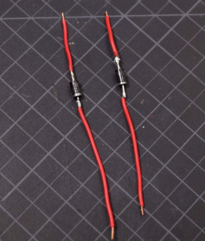
In this project, we will use two Schottky diodes to prevent reverse current flow. You can also use general-purpose diodes but the main reason for using the Schottky diode is that they have a lower forward voltage drop then the general purpose diode.
The negative terminal of the diode is indicated by a silver ring on it.
Trim the two legs of the diode by using a nipper and then solder two pieces of wire to them.
Then apply heat-shrink tubing to the terminal joints as shown in the above picture.
The datasheet of the 1N5822 diode is attached below for your reference.
Attachments
-
7Prepare the Rocker Switch
![]()
![]()
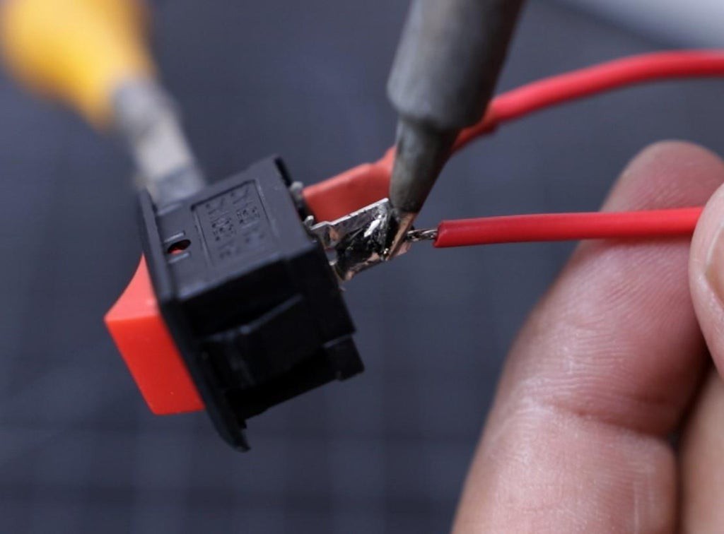
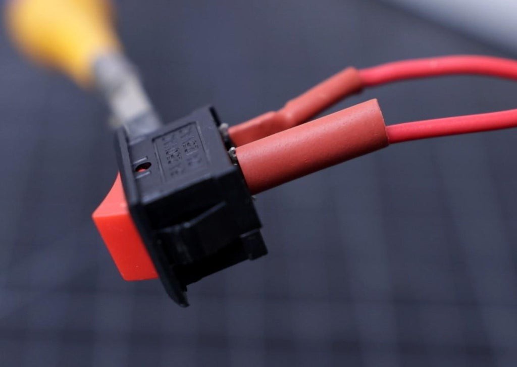
The switch is used between the battery pack and the boost converter input terminal.
Soldering wires to the rocker switch is normally very difficult because the solder does not stick easily to the metal terminals. To avoid this, apply a small amount of soldering flux before soldering the terminal wires.
Tin the terminals of the rocker switch as well as the wires to be solder by applying a small amount of solder.
Always use heat-shrink tubing at the exposed conductive parts.
-
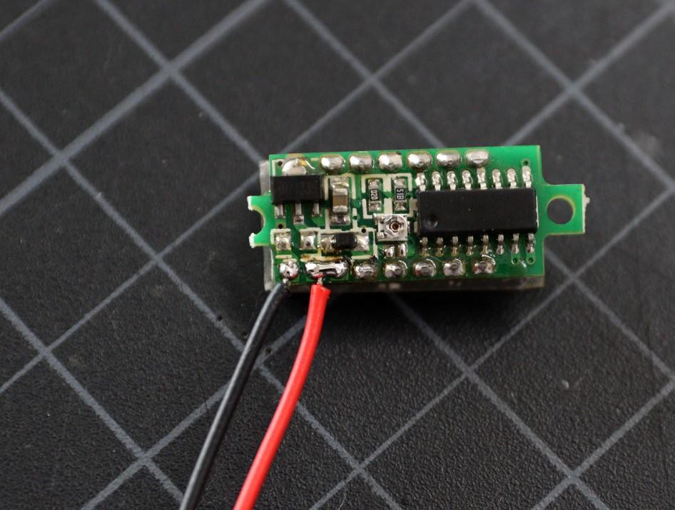
8Prepare the Voltmeter
![]()
![]()
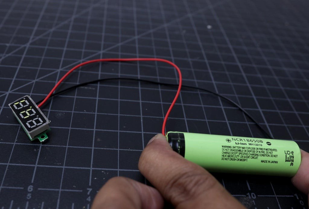
The voltmeter display that I have used in this project has 3 wires. The red and black wire is given to power the meter and the third wire ( yellow ) is given for measuring the voltage allowing for a greater range of measurement.
In our case, we will measure the battery pack voltage only, so there is no need to use the third wire. You can short the soldering pads of the red and yellow wire together.
Then check it by connecting the display to a 18650 battery.
Note: You can buy a two-wire voltmeter instead of three-wire for this project.
-
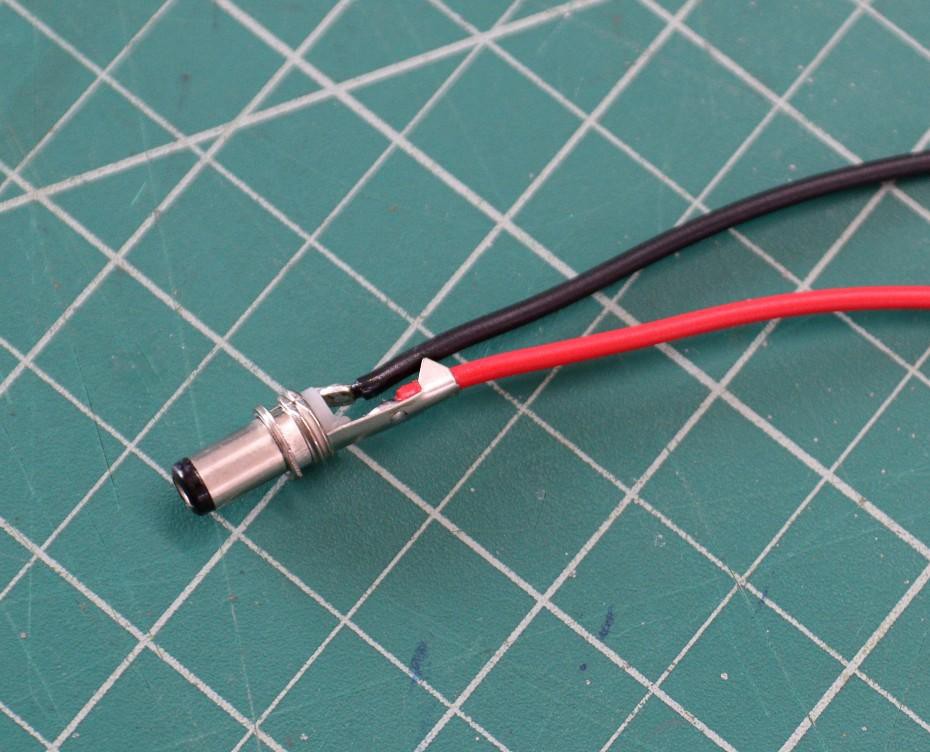
9Prepare the DC Output Jack
![]()
![]()
Now you have to prepare the adapter to connect the UPS output to the router input. First, check the specification of your router to confirm the size of the jack ( Sleeve size ) and the tip polarity. Your router will have a small diagram indicating the polarity expected by it; care should be taken to adhere to this, as an improper power supply may damage the device.
In my case, the size of the jack is 5.5mm and the tip polarity is positive. According to the size, order two male DC Jack. Then solder red wire to the tip (smaller one ) and black wire to the sleeve.
-
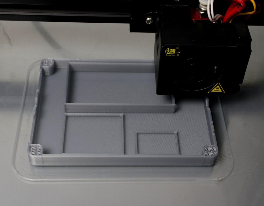
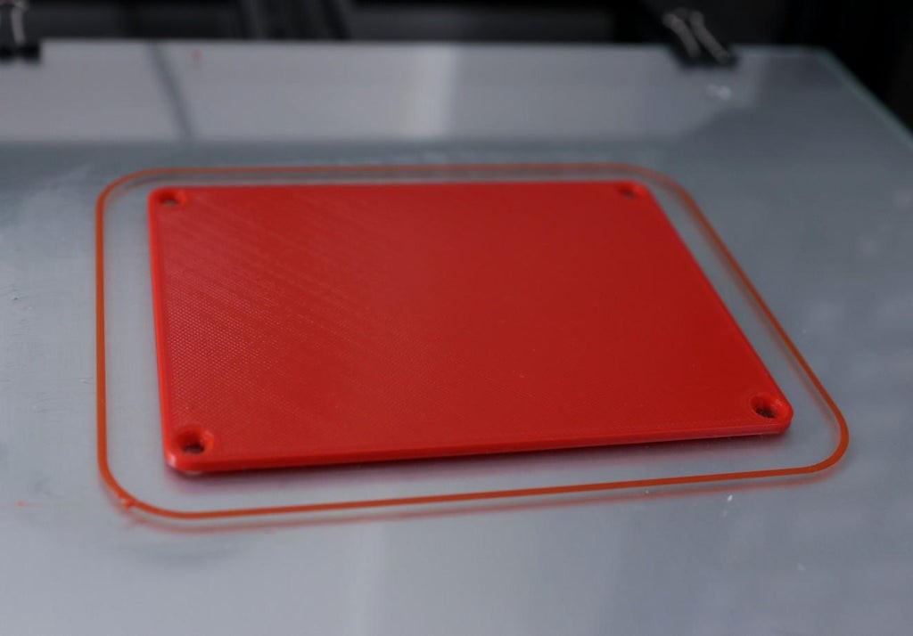
103D Printed Enclosure
![]()
![]()
![]()
I have used my Creality CR-10S printer and 1.75 mm Grey and Red PLA filaments to print the parts. It took me about 3 hours to print the main body and around 1.5 hours to print the top lid.
My settings are:
Print Speed: 60 mm/s
Layer height: 0.2mm ( 0.3 also works well)
Fill Density: 25>#/p###
Extruder Temperature: 200 deg C
Bed Temp: 60 deg C
Download the STL files from Thingiverse
DIY Mini UPS for WiFi Router
A DIY uninterrupted power supply that can power up a WiFi-Router/Modem


Discussions
Become a Hackaday.io Member
Create an account to leave a comment. Already have an account? Log In.