-
1Ordering PCB and Parts
You may want to built this beautiful Desklamp by yourself:
What do you need: Lamp it self:
PCBs: You may find the Gerber Files here: Gerber
Download the GerberZipFiles (V1 or V2) from Github
Upload these Files to JLCPCB, -> Instructions how to to this can be found e.g.: Here
Choose the color of the PCB and the Material: You may try out new Aluminium PCB for better heat dissipation
I choosed white PCB to have a good reflection of the light and for design reasons.
Sent your Order to process and do the payment.
Order your parts for this Project:
You may order your parts at LCSC, Aliexpress or your local electronic parts distributor.
-
2Soldering the PCB
You may want to start soldering on the TOP Layer of the PCB.
Reason for this: It is easier to fix the PCB on you desk if the LEDs on the bottom side are not soldered yet.
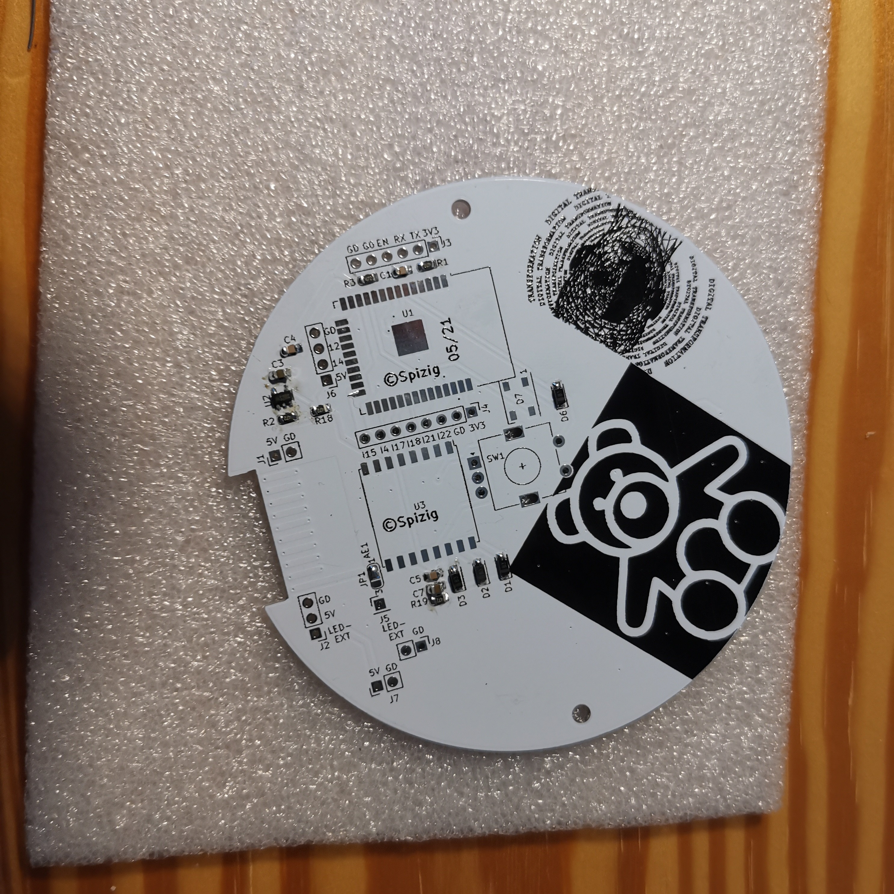
Start with the smallest parts first. Resistors, Capaitors, LDO and Diodes should be soldered first.
Watch for polarity of the Diodes!
You Board should look after the first steps like this:
![]()
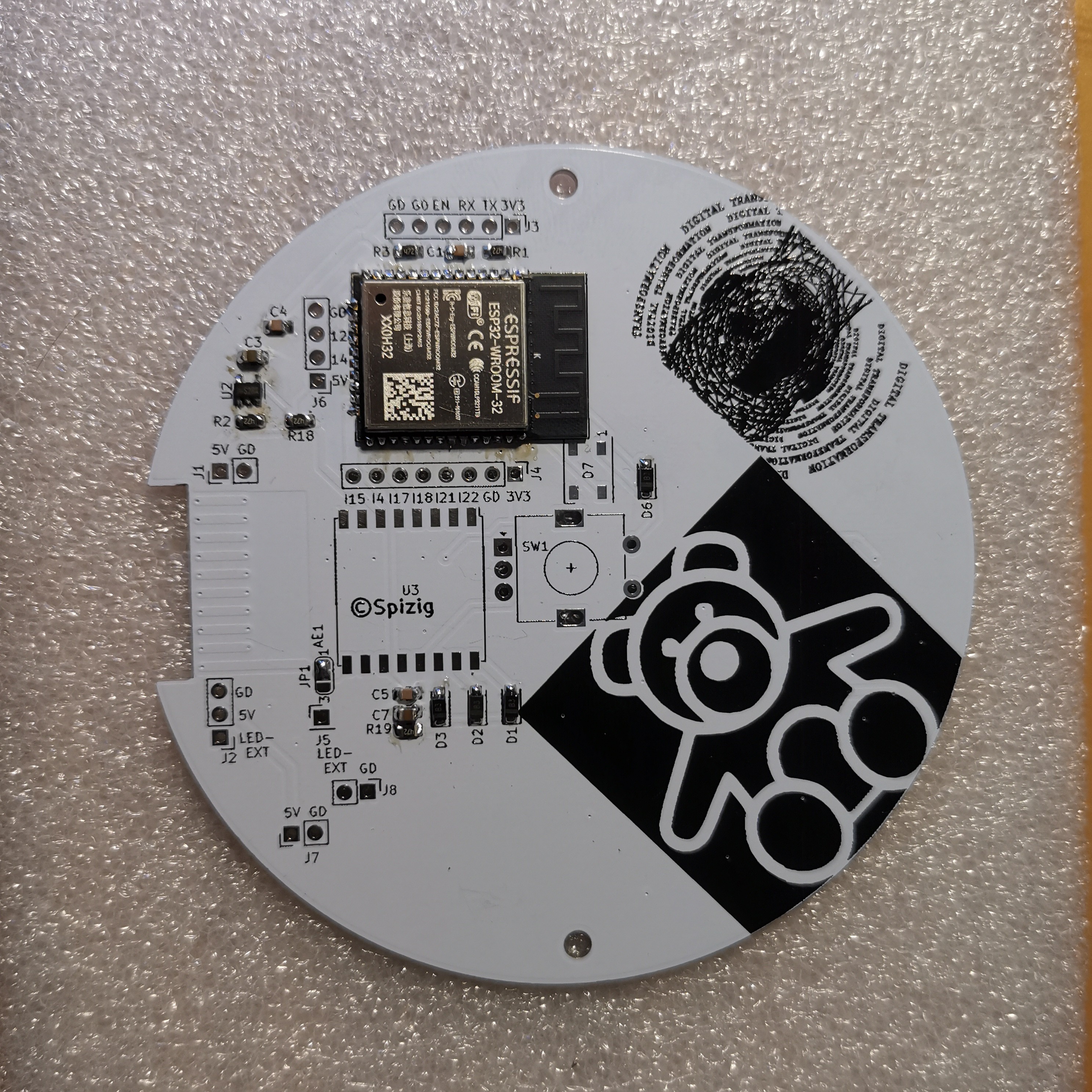
Solder the Main Processor: ESP32:
![]()
You may notice: There is a little solder bridge at AE1, next to the lora Chip. You need to solder this to enable the LORA Antenna
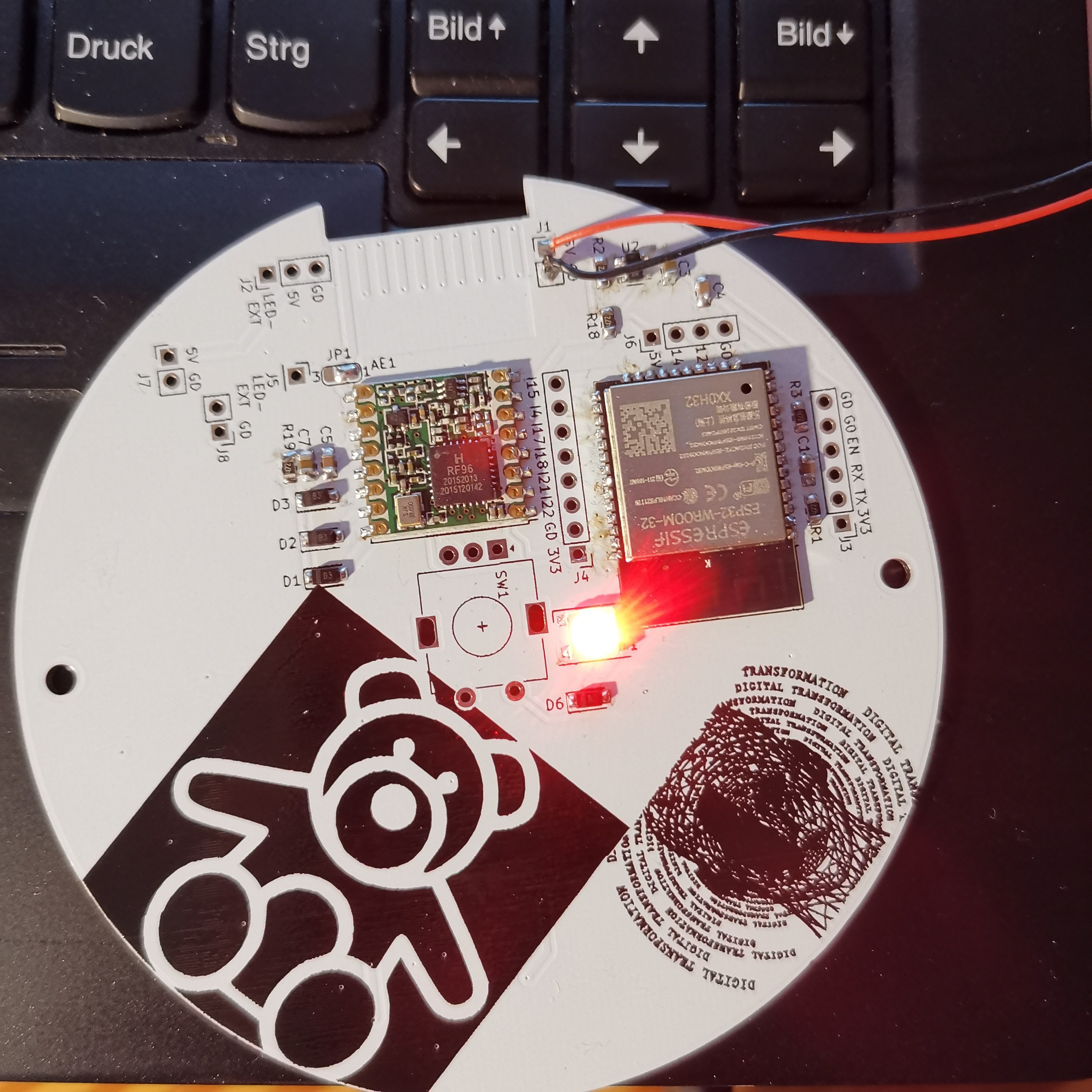
Now lets solder the LORA Module and the TOP LED:
![]()
Now we can start to program the Board with a small Demo Arduino Sketch to see if everything is working.
-
3Solder the bottom side of the PCB Board
Now it is time to flip the board to the other side.
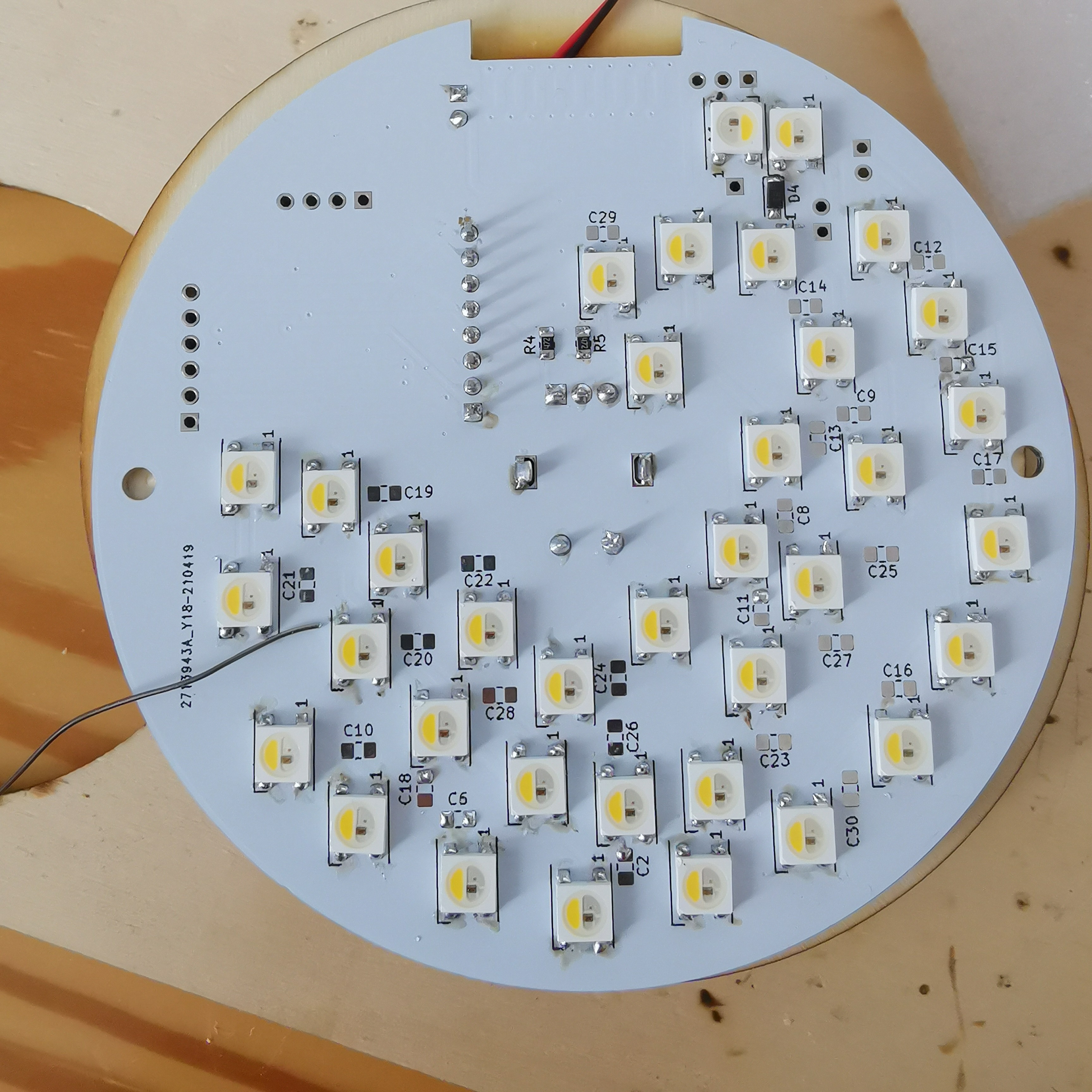
Lets populate all the LEDS on the bottom:
Watch for Polarity carefully. You may notice: The orientation of the board is the same for all LEDs.. EXCEPT for ONE! The one on the far North D5(next to D4 in the below picture). Thats why I wrote a "!" in the Silk Screen under this LED to remind me of this :-)
![]()
Finally lets add some capacitors. You may need some but not all of them.
-
4Solder the EC11 Rotary Encoder, the Air Quality sensor and the Gyro Board
Now lets solder the Air Quality Sensor Breakout Board, the Gyro Breakout Board to Connector J4. It is up to you if you want to solder this on the Top or Bottom side of the PCB.
Now lets add a LDR, Light dependent resistor for Light intensity measurments. I connected this sensor to the remaining I15 on J4.
"HERE Will BE A PICTURE of the soldering"
You may solder the EC11 Rotary Coder as your last part. Once this is solder the handling of the board becomes difficult.
-
5Programm your Microcontroller with Arduino IDE
You may now finally program your board with the ARDUINO IDE
To do this you need to add the ESP32 Boards to your Arduino IDE: Here is a video of how to do this.
Download the Code Files from here in the code section(WORK IN PROGRESS): Link
Install various Arduino Libaries: How to do this is described in this Tutorial
Fastled
- https://github.com/FastLED/FastLEDRGBW for SK6812:
- Extended by Christoph Wempe
- https://gist.github.com/CWempe?direction=desc&sort=createdAdafruit BME/BMP280/SGP30 sketches/libs
- Please consider buying their products due to their great work in Arduino libs
- https://github.com/adafruit/Adafruit_SGP30
- https://github.com/adafruit/Adafruit_BMP280_LibraryBosch BME680 BSEC Lib
- https://github.com/BoschSensortec/BSEC-Arduino-libraryAndreas Spiess
- OTA Sketch for OTA Update of the ESP32 over Wifie
- https://github.com/SensorsIot/ESP32-OTAHideakitai MPU9250 Sketch
- https://github.com/hideakitai/MPU9250knolleary pubsubclient
- /pubsubclient/blob/master/examples/mqtt_auth/mqtt_auth
- https://github.com/knolleary/pubsubclientCustomize your Wifi Credentials before Uploading.
Everything you might need to change is marked as "REPLACEMEUSER"
Upload your code with the following HW Adapter M5 stack ESP32 Downloader
To do this plug in this M5Stack Programmer to the connector J3
-
6Fit everything into the Housing
No is the time to fit everything into the Head of the lamp.
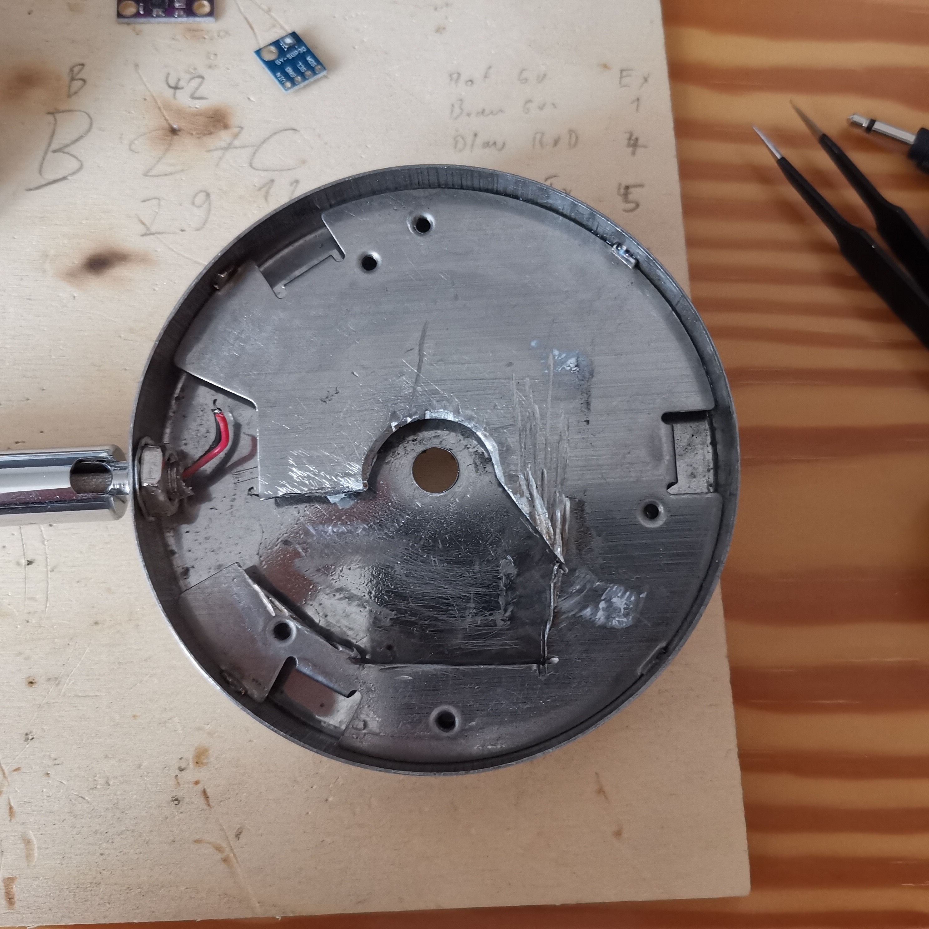
To fit everything in this Tight space you must DREMEL some pieces out of the Metal head. With a DREMEL this is done in around 5 min.
Your Lamp Head must look like this before installing the PCB.
![]()
To ensure shortcuts it is advised to use some isolation tape on the inside of the Head. This prevents shortcuts on the metal of the Head. Once everything on the inside is coverd with tape you may fit in the PCB and solder the Plus and minus wire to the PCB Connector.
-
7Power Supply
If you want to use the Desklamp without you PC alone you must replace the original Power Supply.
I recomend this Power Supply from Reichelt
MW 3IP25GS Universal-Schaltnetzteil, 27 W, 3 - 12 V, 2250 mA
Please buy a proper 5V DC Power Supply that can deliver a minimum of 2.5Ampere. Please be aware that you MUST USE a save power supply. NEVER CONNECT 230V or 110V directly to this PCB! Only 5V DC(YES DC no AC-not even small parts of AC) is allowed. It is your responsibility. It is your live.
-
8Install the Volume Knob on the Rotary Encoder
One final step is now fixing the volume Knob. The screw that comes with the EC11 Rotary encoder helds the PCB in Place.
Add the two screws on the side to keep the Glas of the lamp in place.
On the outside firmly press the Aluminium Volume Knob on the Rotary Knob to get it in Place
-
9Start the Desklamp
If you rotate the lamp clockwise or counterclockwise the lamp should start.
You should see the Main LEDS red or BLUE.
Double Click to enable white Light
Click once to shut down the Desk lamp.
If you enable all 36 LEDS in the credentials.h file it may look like this:(reduced Brightness to 65/255
MQTT:
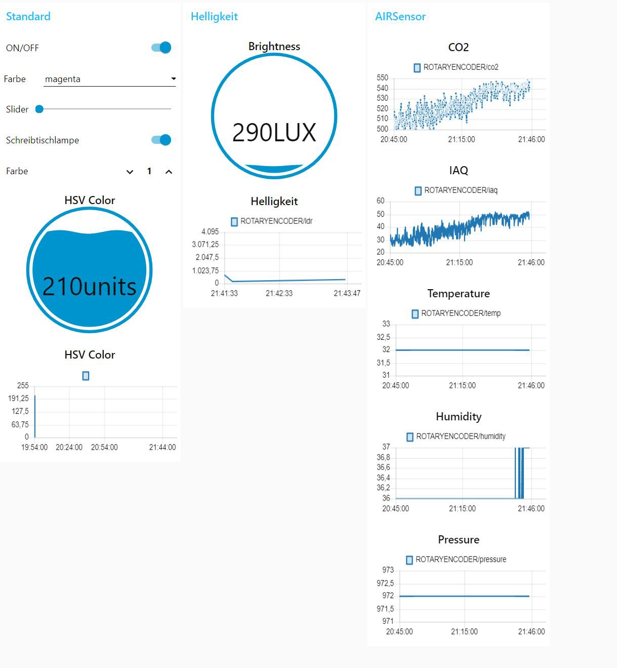
The Desk Lamp transmits now every 3 seconds the recorded Values to MQTT Server.
This might look like this if you have Node red installed:
Right now there is no Automatic color change on Bad Air Quality. You might do this on the Backend on NodeRed Side
LoRaLamp AIRQuality
A Desklamp for your "Work from Home" Desk with Air Quality Sensor, LoRa, WiFi, MQTT that reminds you to open your windows for Fresh Air
 Ulrich
Discussions
Become a Hackaday.io Member
Create an account to leave a comment. Already have an account? Log In.