Michael Rangen
-
Thanks :)
11/07/2021 at 10:09 • 0 commentsI've had a lot of fun pouring my passion into this project and I just want to say thanks for taking the time to check it out :)
Cheers,
Mike
-
Contest Entry Video
11/07/2021 at 10:03 • 0 comments -
Motor Driver Board Demo
11/07/2021 at 10:01 • 0 comments -
Many Button Demo
11/07/2021 at 10:01 • 0 comments -
Dual I2C OLED Demo
11/07/2021 at 10:00 • 0 comments -
Components List Updated
11/07/2021 at 09:46 • 0 commentsThe BOM was available previously, but now the components list has been added to the Hackaday.io project page! I really enjoy how it was able to automatically add descriptions for some of the parts I added!
-
Uploaded Instructions
11/07/2021 at 09:44 • 0 commentsDetailed instructions have been added to the project page!
-
Uploaded Project Files
11/07/2021 at 09:43 • 0 commentsEverything you need can be found in the project files section.
-
Attempt #1 - 2017
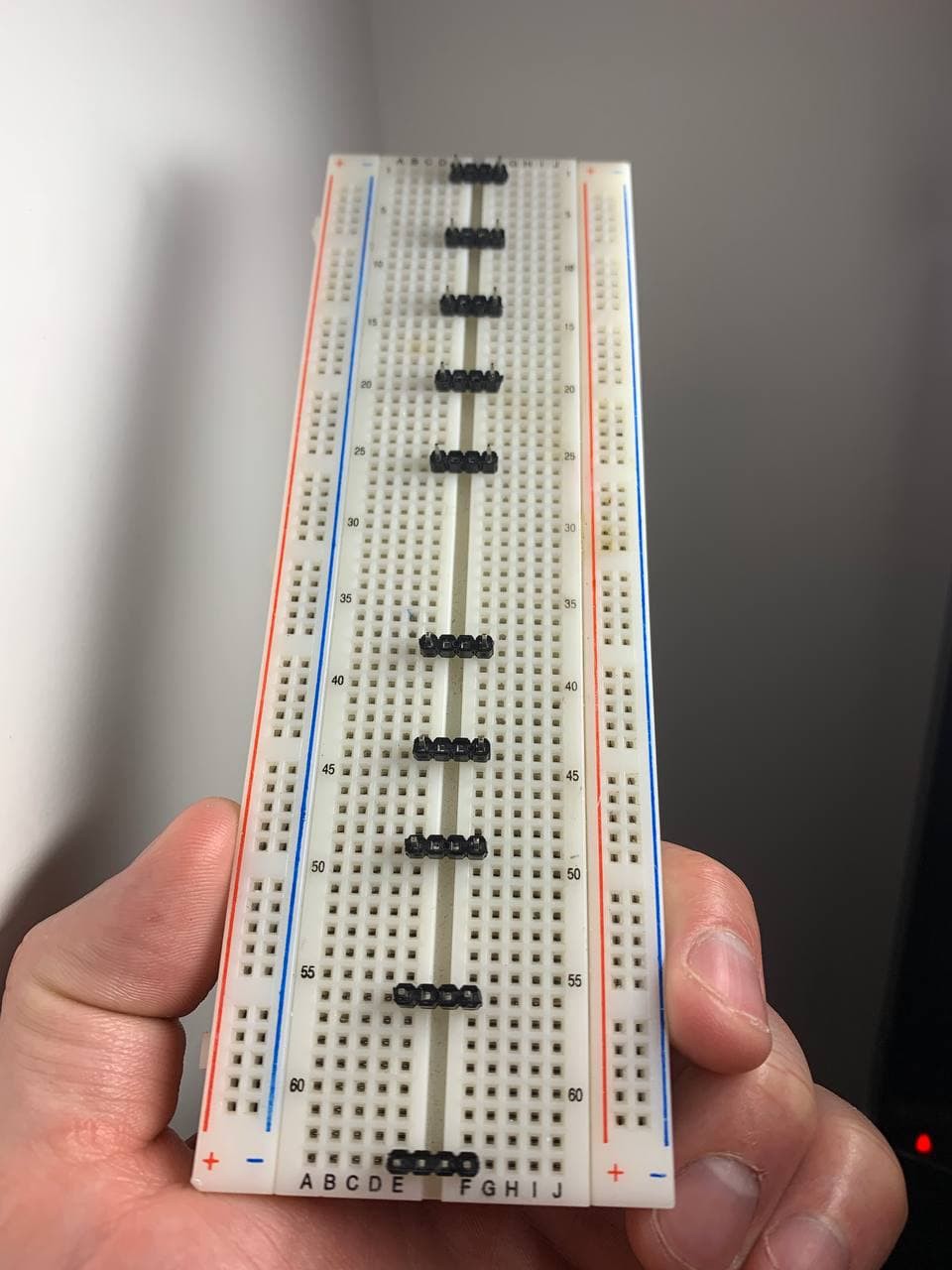
08/11/2021 at 06:11 • 0 commentsBack in 2017, I had this interesting idea - What if you stretched a dev-board out like an accordion? From fat and compressed to stretched and skinny? I played with this idea and started experimenting with male header-pins; I would take 4 pins, remove 2 from the center, and start placing them on an empty breadboard, just feeling things out.
![]()
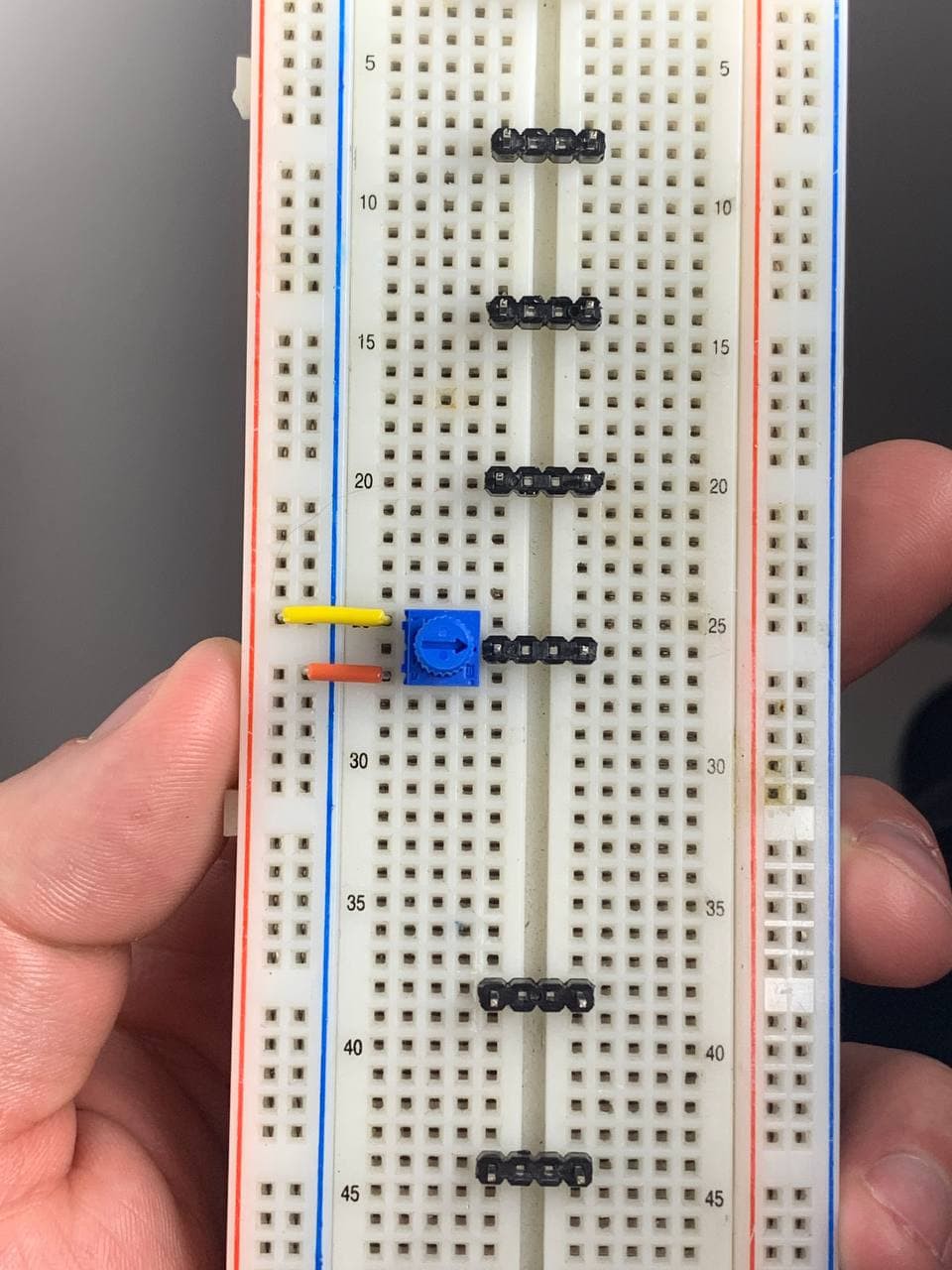
It seemed natural to have my pins line up with the gaps in the bus lines. Especially once a pot was placed on the board. "When would I ever need a conection directly from an I/O pins to a bus rail?", I thought. I decided to place the microcontroller in the middle, so I left some room for it and the supporting circuitry. With the micro in the middle, half the traces would run upwards and the other half downards; nothing would get too cramped.
![]()
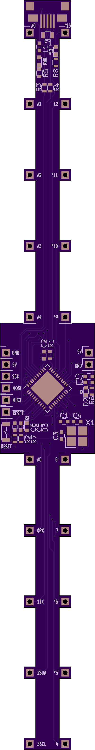
I decided to go with an Atmega32u4, for the built-in USB, in a QFN package. I felt like rotating it 45° would make it easier to run traces, and I'd seen it implemented before, so it felt like a good choice. I made an adapter board to convert the 2x3 ICSP to a 1x6, so that I'd have those pins accessible on the breadboard as well. I went with a 4 layer design because, at the time, I honestly didn't think this could be done in 2 layers; I even went down to 0603 parts for the first time! Once I settled on something I felt would work, I placed my order at OSHPark.
![]()
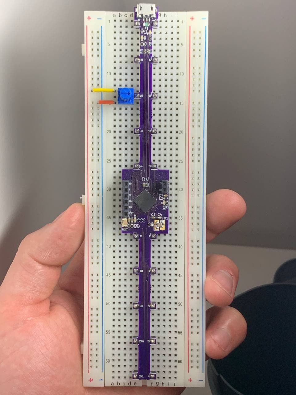
It was really exciting when the boards and parts came. It was a big challenge, I had a lot of really small 0603 parts, some tweezers, a syringe of solder paste, a hot-air tool, and a cheap-o soldering iron. It wasn't all that pretty, my design wasn't perfect *cough* don't look to closely at the crystal *cough* but I did get it working. I was able to solder everything, flash the bootloader, and upload some code through the Arduino IDE. Success!
![]()
I had fun playing around with it.
I emulated a keyboard to make a USB controller for playing retro games on a NES emulator:
![]()
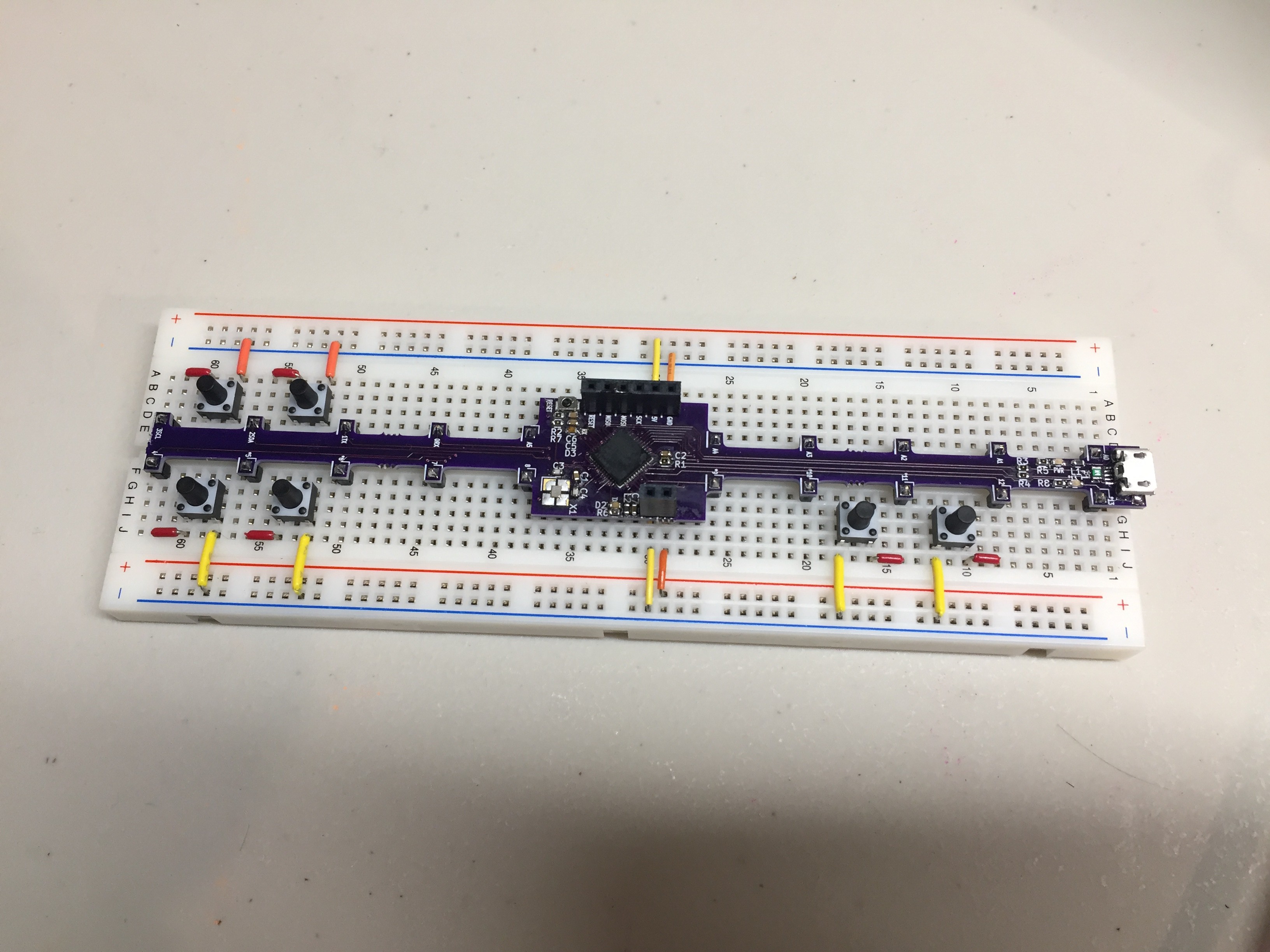
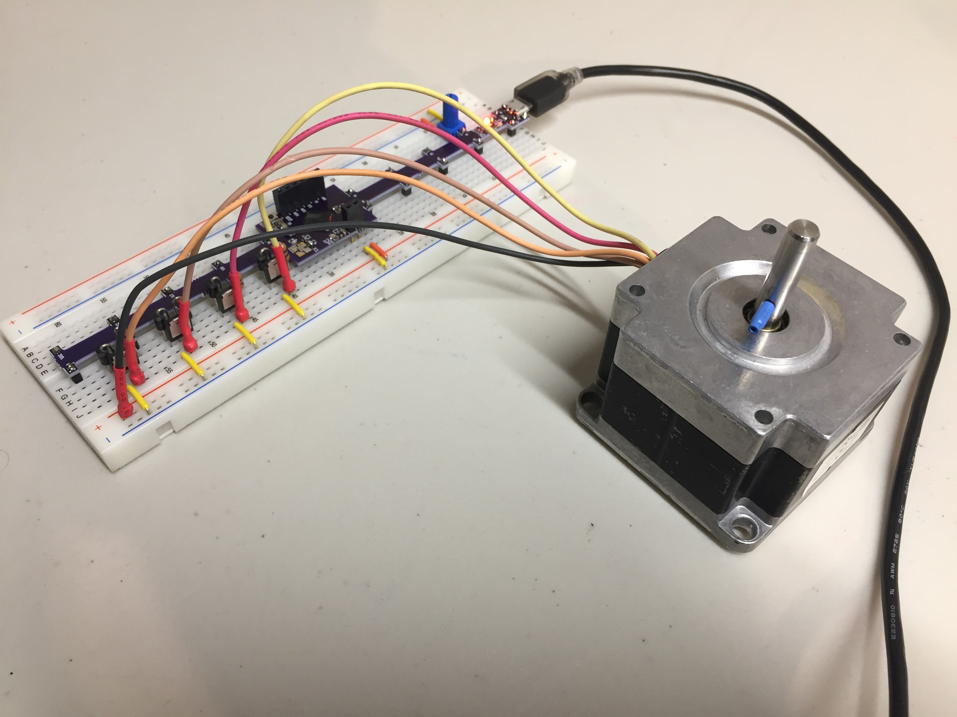
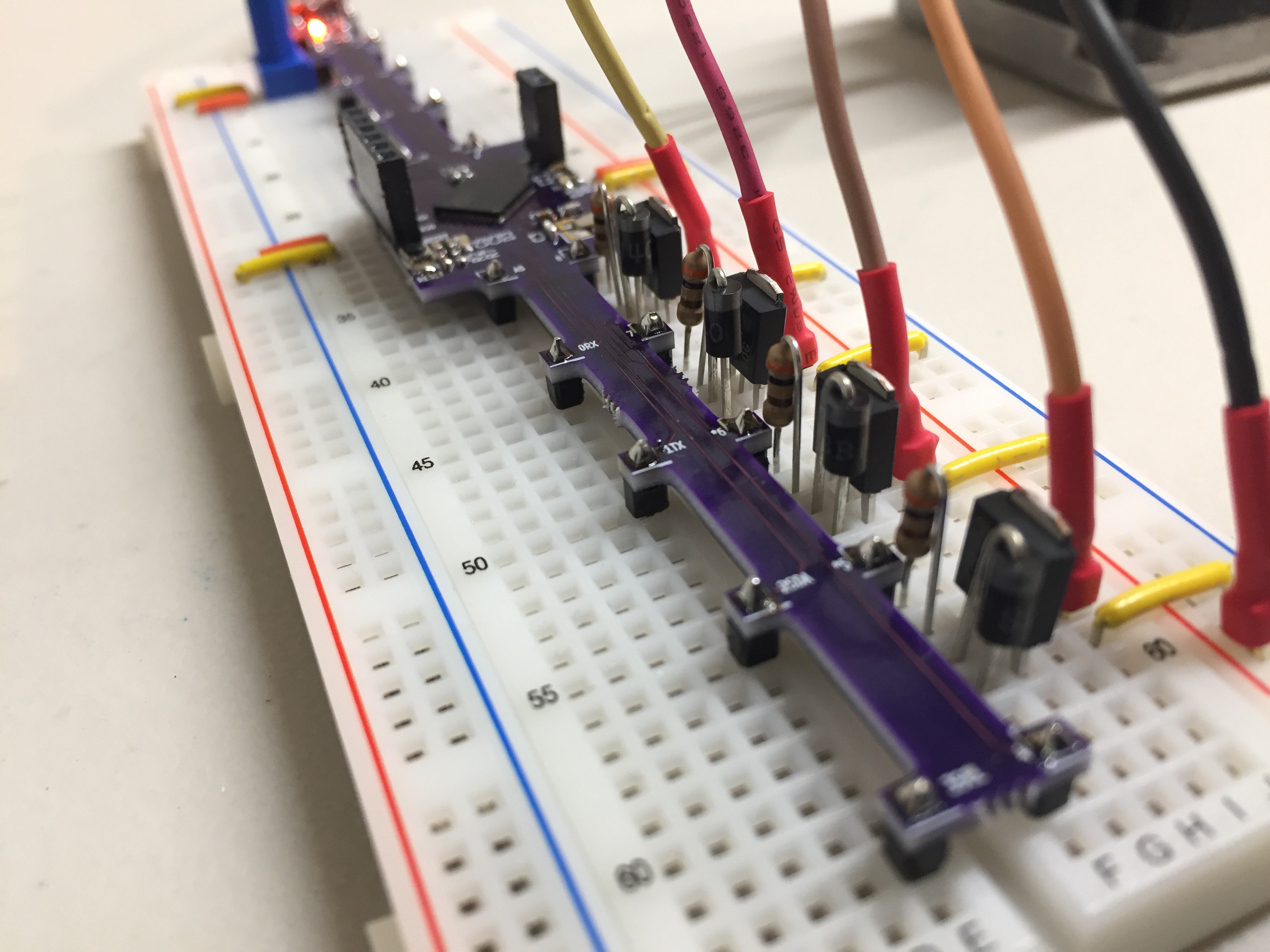
I made a simple unipolar stepper-motor driver:
![]()
![]()
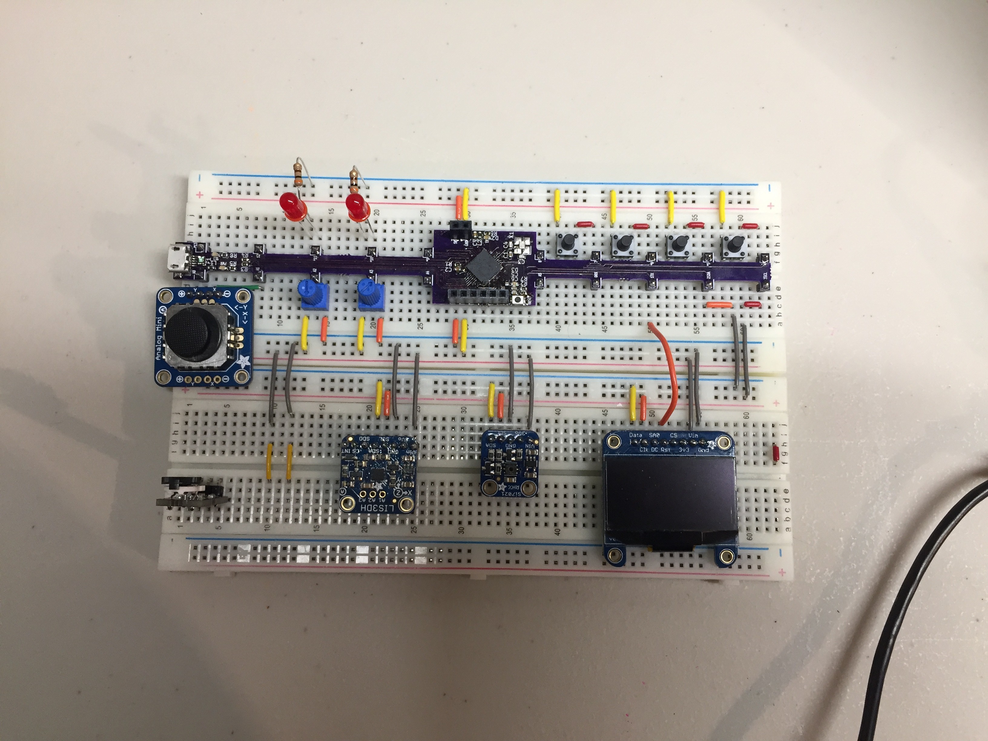
And experimented with using the bus-rails for I2C devices:
![]()
It was pretty fun and I was proud of my achievement; I cleared a lot of new challenges for the first time with this project. I took a novel concept through to a working prototype, I designed a 4-layer PCB with power-planes, I made a lot of my own footprints (I am so lucky that crystal still worked despite my screw-up), I designed with 0603 parts, I used a QFN microcontroller, and I soldered it all up without fancy equipment or stencils - and it worked!
I'd also like to take a moment and thank Chris Gammell. When I studied electronics engineering technology at NAIT (Fall 2010 - Spring2012), PCB design was not yet included in the course; so I had to teach myself! If it weren't for Chris's KiCad tutorials, I would never have been able to pull this off.
-
Github Repo Up!
08/09/2021 at 06:49 • 0 commentsI finally put most of the files up publicly on my GitHub page.
- Pictures
- Videos
- Pinouts
- Schematics
Still need to add board config files, firmware, and get my board added to the CircuitPython repo.
M4-Breadstick (Retired) → Raspberry Breadstick
A long and thin development board, with spaced out I/O pins to minimize the length and number of jumper wires required.