Commit 7d753bf
Minor component & silkscreen changes.

What worked:
- SPI flash
What didn't work:
- Solar charging
- 1.8V buck converter
SPI flash orientation was fixed and the chip was immediately detected by my programmer. No problems there.
Adding a 43K resistor (top left, 0603, not soldered in image) to the MPPC pin didn't seem to do much. I'm probably going to figure out the solar charger in a separate PCB so I don't have to order 6-layer boards every time.
It turns out that I also had the wrong footprint for the 1.8V buck converter IC (top center, 8-ball BGA, TPS62748). The IC is 0.4mm pitch, and the footprint in the KiCAD default library was 0.5mm, I didn't notice.
For some reason, the same chip in the last batch was placed so perfectly in the center that it didn't raise a problem on both boards (I have 2 boards assembled each revision).
This time, none of them worked.
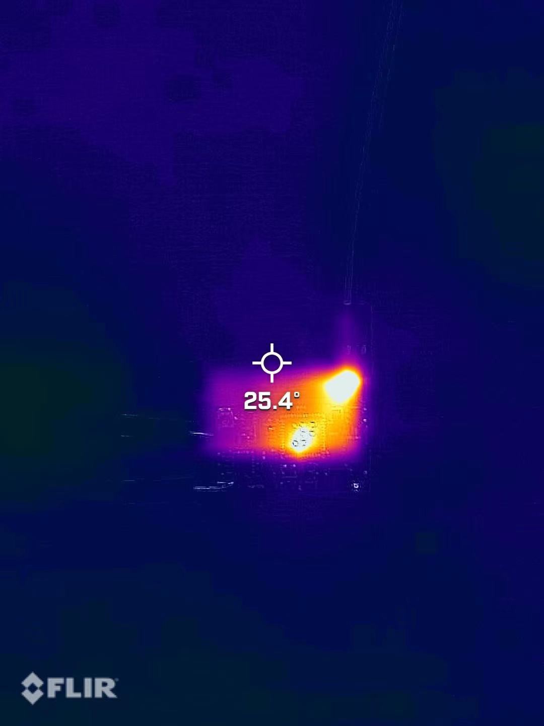
One was drawing >500mA idle and heating up like crazy, the other one just had nothing on the 1.8V rail.
Hotspot on the top is the 3.3V LDO, the one on the bottom is the 1.8V buck. (alignment’s pretty bad)
No big deal though, I just removed the 1.8V buck converter and soldered a wire to it. I'll feed 1.8V manually while testing.
More updates on the RF section coming soon.
Also, if anyone has any idea of how to make the solar charger IC (LTC3105) work properly, please leave a comment.
Discussions
Become a Hackaday.io Member
Create an account to leave a comment. Already have an account? Log In.