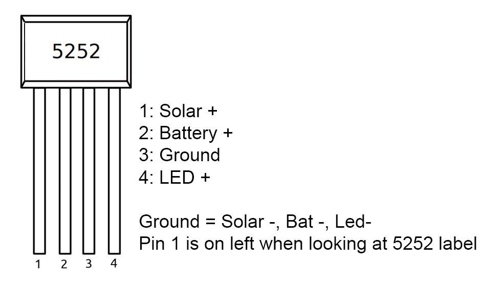
The controller has two tasks
1. Charging the Battery:
Isolate the Solar Panel and Battery when the battery is fully charged and Isolate the load from the Battery when the battery voltage is low.
2. Driving the LED:
Capable to drive the selected LED ( ability to handle the required voltage and current ) i.e Boost the battery voltage ( 1.2V ) to LED operating voltage (3.2V) or higher
Here we will use a cheap QX5252F IC as a controller.
The main features are:
1.Suitable for a single AA NiMh/NiCd battery
2.Operating Voltage: 0.9V-1.5V
3.Output current: 3mA-300mA ( Our requirement is 93.7mA )
4.Integrated Schottky Diode
5.High Efficiency up to 84>#/p###
6.Low quiescent current: 17uA ( When the circuit is not working / standby )
7.Only an external inductor is required for making the Circuit
 Open Green Energy
Discussions
Become a Hackaday.io Member
Create an account to leave a comment. Already have an account? Log In.