Close
0%
0%

DIY SOLAR SOLAR LAMP

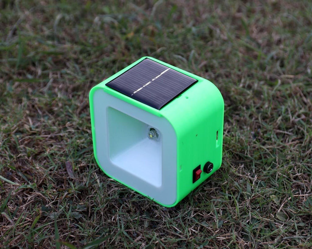
A low-cost solar lamp that can be used as a replacement for harmful kerosene lamps and a learning Kit for STEAM Education.

Similar projects worth following
Solar energy is clean and limitless, and the operational costs are close to nothing once you’ve installed a solar panel as no fuel is needed to create a considerable amount of energy. And a single kerosene wick burns an estimated 80 liters of fuel, producing more than 250 kilograms of carbon dioxide per year.

To help people living in remote places with limited access to electricity, we made a low-cost solar lamp as a replacement for a harmful kerosene lamp.

The lamp is designed as a kit form so that it can be used for STEAM education. This will introduce students to understand the basics of working with LED, Solar panels, and an off-grid solar system.

The main purpose of this DIY Solar Lamp is to provide clean and economical light to people living in remote places with limited access to electricity, by replacing their harmful kerosene lamps.

Benefits:

 1.Use of the solar lamp will decrease the amount of local air pollution and saves energy.

 2. It also came out as an alternative business model with the potential to strengthen the overall rural economy by generating technology-based livelihood opportunities.

 3. It can provide access to solar lamps at an affordable price to a wide range of audiences living in remote villages that are deprived of clean energy access.

STEAM EDUCATION KIT :

Though the initial goal was to make the lamp for providing basic lighting to the village people, later 

I have upgraded my design to make a DIY PCB kit so that children can be used it for fun learning. 

How Does It Work?

The working of the Solar Lamp is similar to a stand-alone Solar Photovoltaic ( SPV) System and comprises of four basic components.
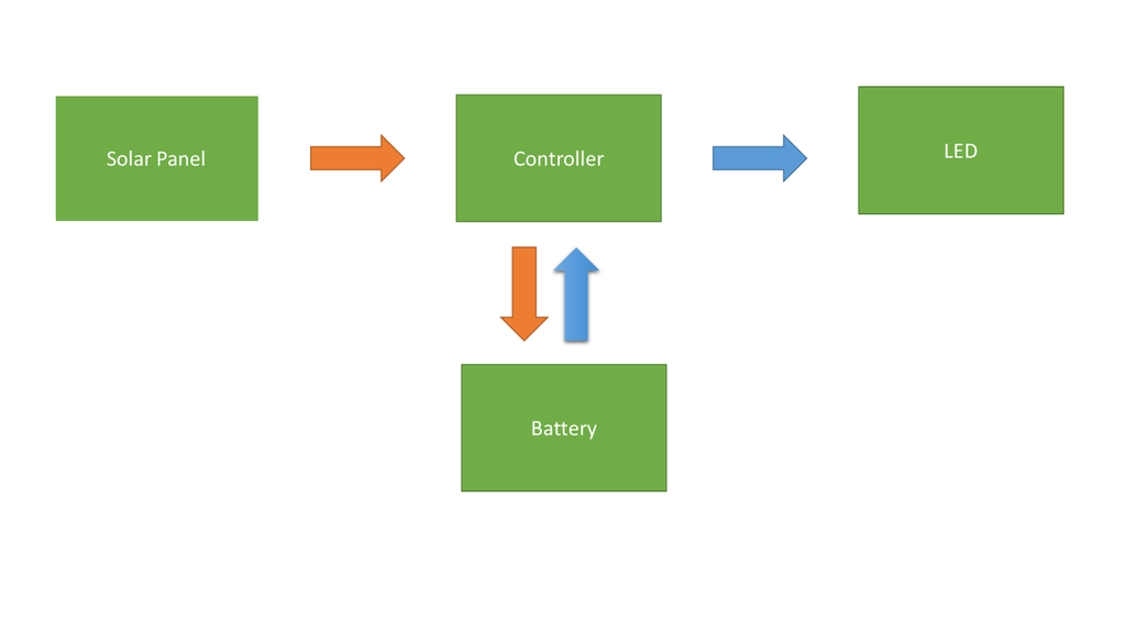

Components Of a Solar Lamp:

1.Solar Panel: Convert Solar Energy to Electrical Energy

2.Controller: Charge the Battery (Charger) and drive the Load (Driver)

3.Battery: Store the Electrical Energy

4.Load (LED): Provide the desired light output

How does the Circuit Works?
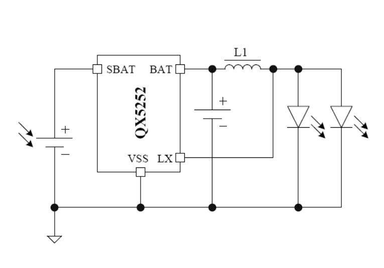
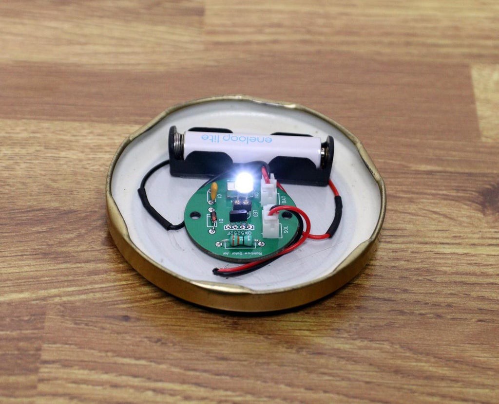
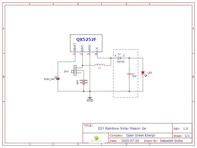
The heart of this Solar Lamp is a very small 4 legged IC QX5252F. It works similar to the "Joule Thief " circuit. But the advantage of using this chip is that it does not require a bulky and heavy toroid. It does the same job using only a simple inductor, single AA / AAA battery, and a LED.

It requires only an external inductor for making the Circuit. The LED current can be changed by using a different value inductor. The chart is shown in the above picture. I have used a 33uH inductor.

Connection :

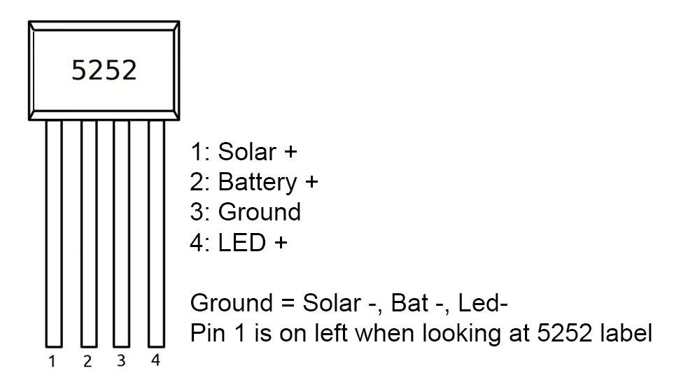
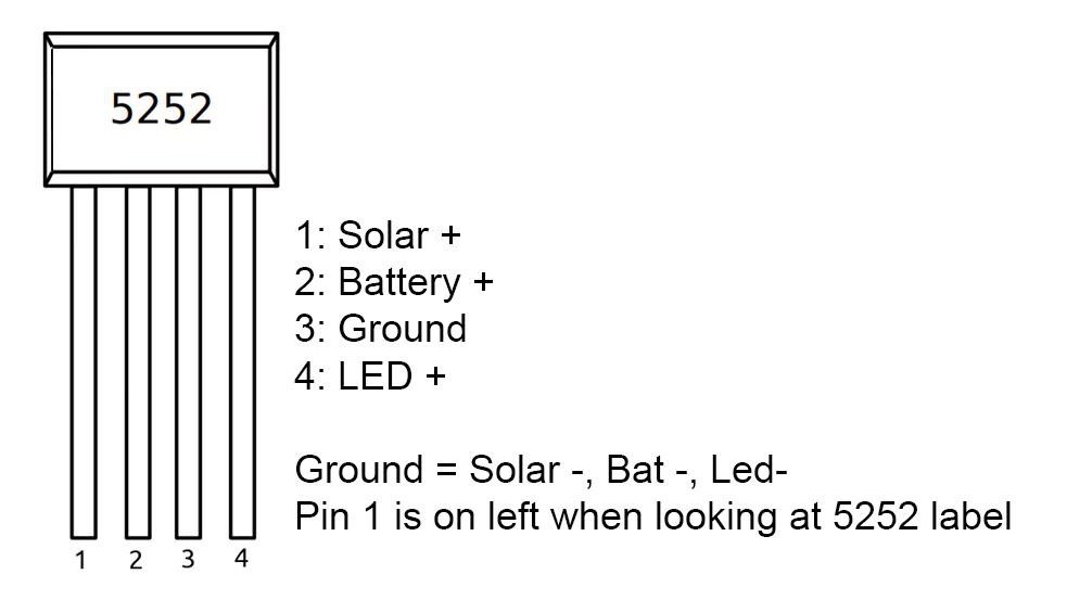
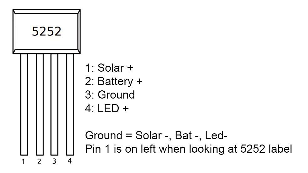
Pin-1 -> Solar panel positive terminal

Pin-2 -> Battery positive terminal and one leg of Inductor

Pin-3 -> All ground ( Solar panel, Battery, and LED negative terminal)

Pin-4 -> Another leg of Inductor

QX5252 Data Sheet.pdf

Adobe Portable Document Format - 391.50 kB - 07/30/2021 at 08:32

Preview

Schematic_Solar Lamp_2021-07-30.pdf

Adobe Portable Document Format - 18.55 kB - 07/30/2021 at 08:46

Preview

Gerber_Solar Light Bulb V2.1_2021-07-30.zip

https://www.pcbway.com/project/shareproject/Solar_Light_Bulb_V2_0.html

x-zip-compressed - 41.51 kB - 07/30/2021 at 08:47

Download

3D Printed Enclosure.zip

https://www.thingiverse.com/thing:4660405

x-zip-compressed - 1.52 MB - 07/31/2021 at 19:35

Download

Schematic_Solar_Rainbow_Light.pdf

Adobe Portable Document Format - 34.26 kB - 07/31/2021 at 19:42

Preview

View all 6 files

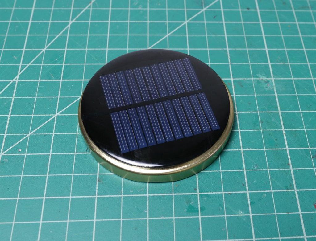
  • 1 × Solar Panel - 2V
  • 1 × IC QX5252F
  • 1 × 8mm Strawhat LED
  • 1 × 33uH Inductor
  • 1 × Slide Switch

View all 6 components

  • Fun Experiment with New PCB

    Open Green Energy08/07/2021 at 19:37 0 comments

    You can find the assembly Instruction and more details on  my Instructables page
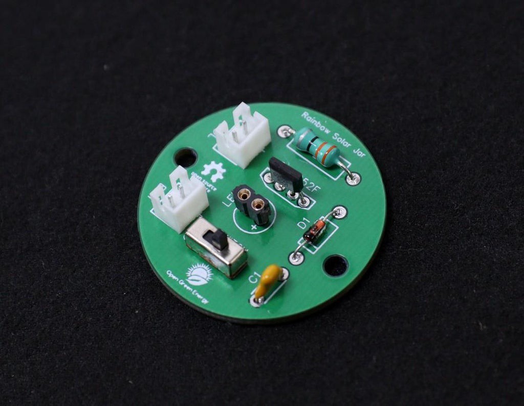
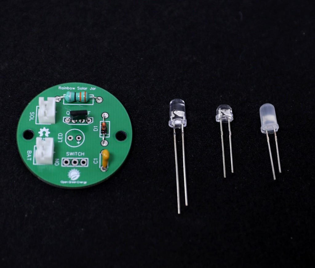
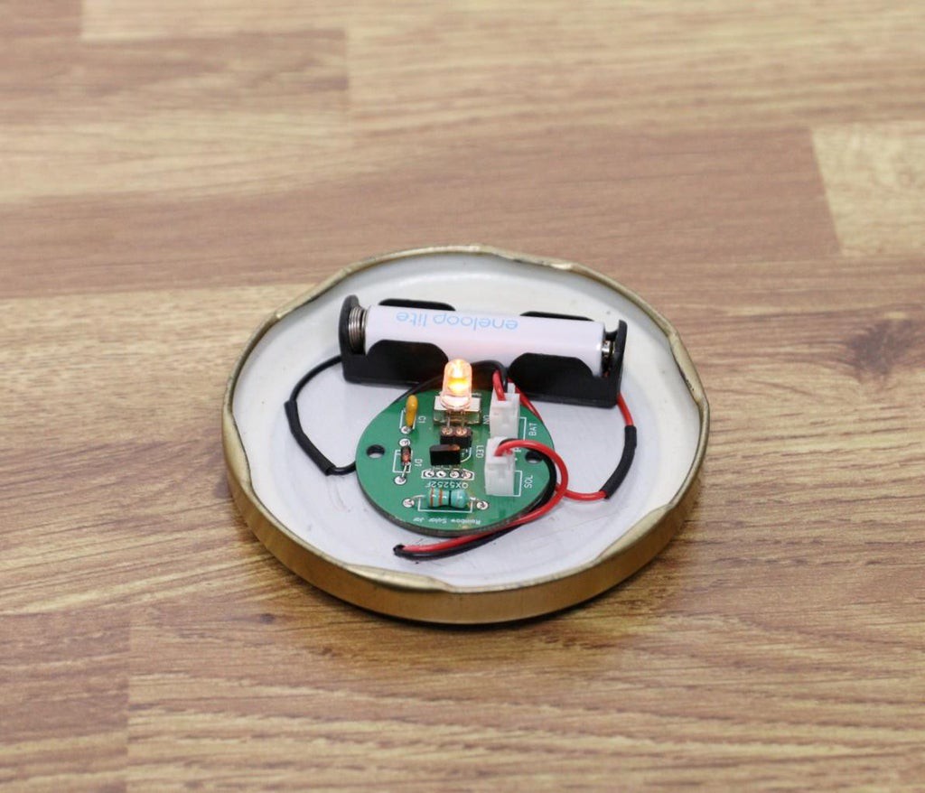
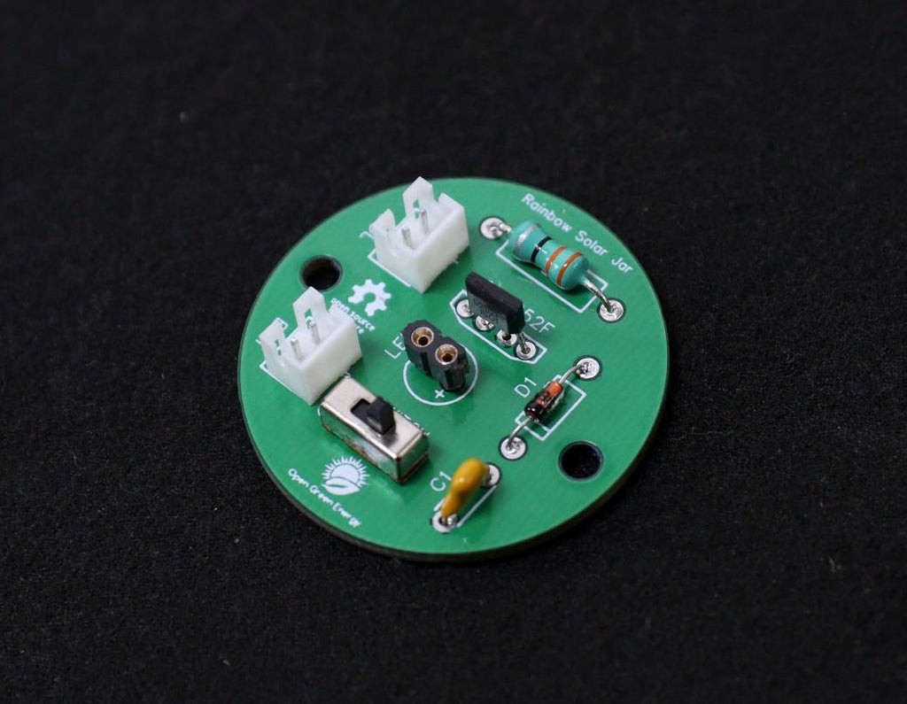
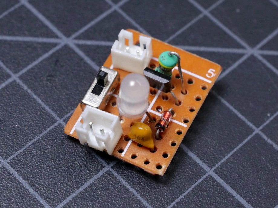
    We can solder a 5mm LED onto the PCB directly. But to test a different kind of LED, here I have soldered a two-pin female header. By using this, I can easily swap between different kinds of LEDs one by another.

    In the next few steps, I will test with the following LEDs:

    1. Strawhat LED

    2. Colour Changing RGB LED

    3. Candle Flickering LED

    4. Fairy String Light

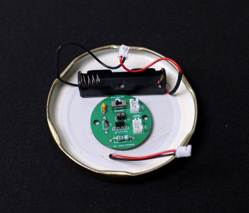
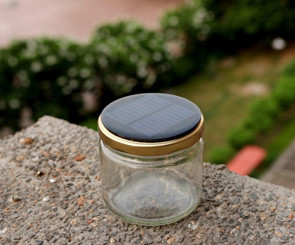
    Now slide the solar lamp switch to ON position and then place the Jar in the bright sunlight.

    The solar cell will charge the battery.

    1. Strawhat LED :

    For a quick test, insert the LED into the female header.

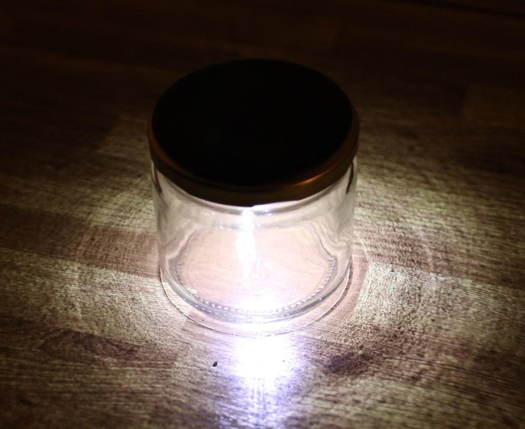
    Then slide the solar light switch to the ON position and cover the solar cell with your hand. The light should be turned ON.

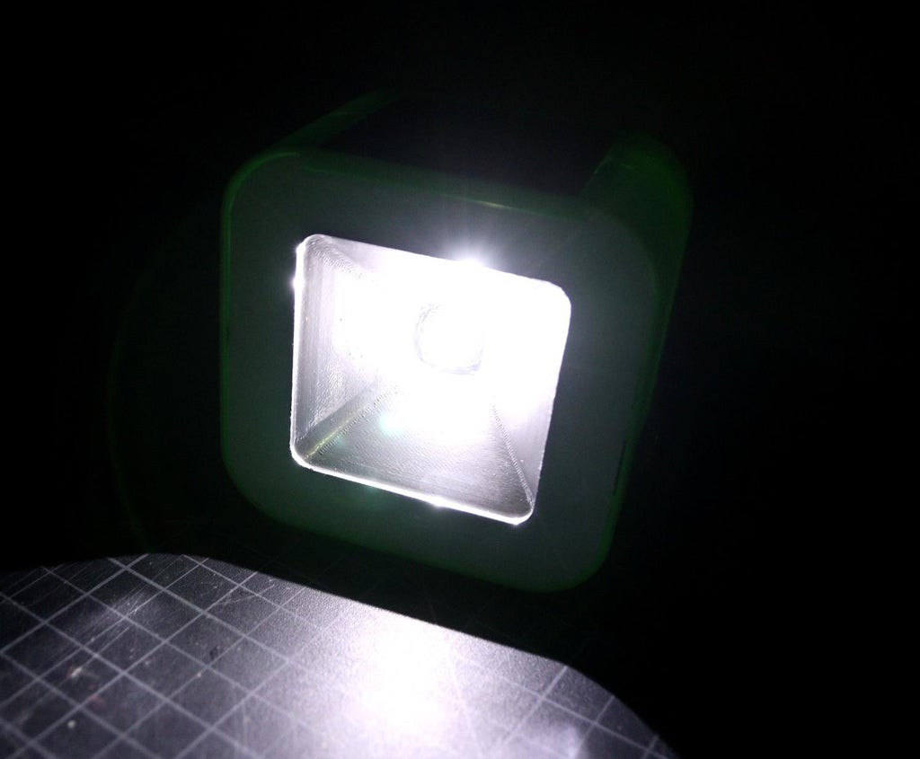
    Here I have used the 5mm Strawhat LED. The output of the lamp resembles a flashlight.

    2. Colour Changing RGB LED: 

    You can use your creativity to produce various attractive effects on the lamp.

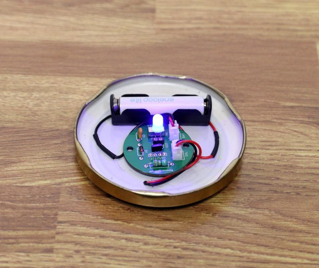
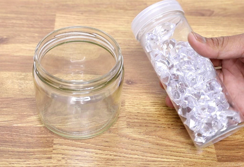
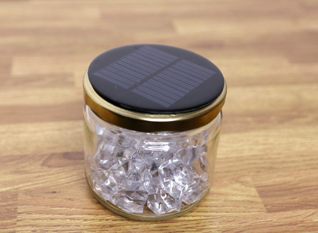
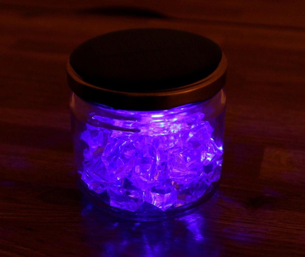
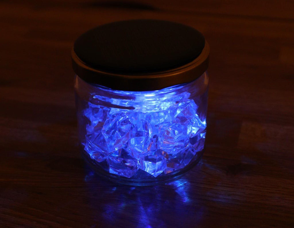
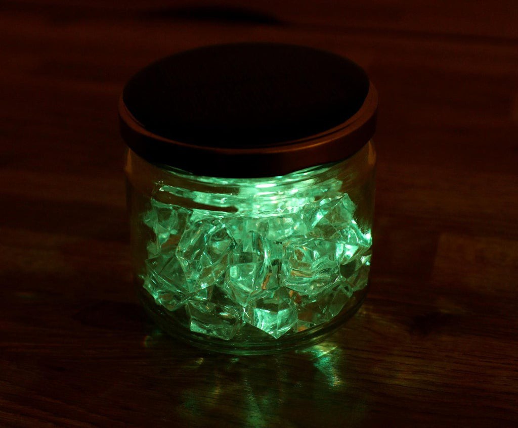
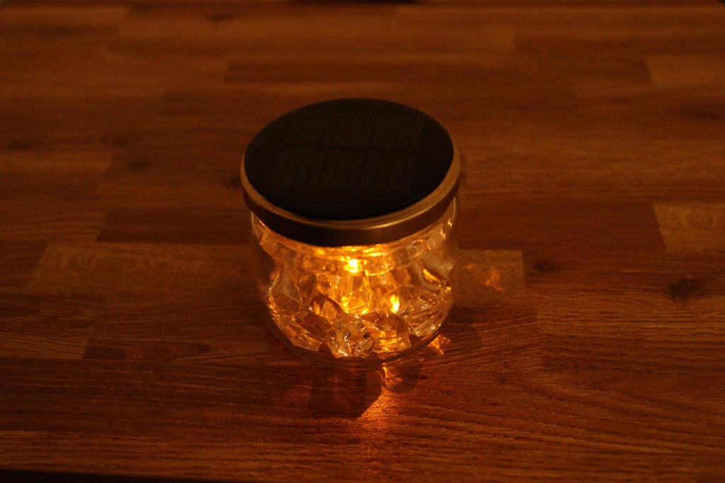
    I have filled the jar with acrylic pebbles to get the glittering effect.

    Here I have a two-pin RGB LED. Insert the LED into the female header.

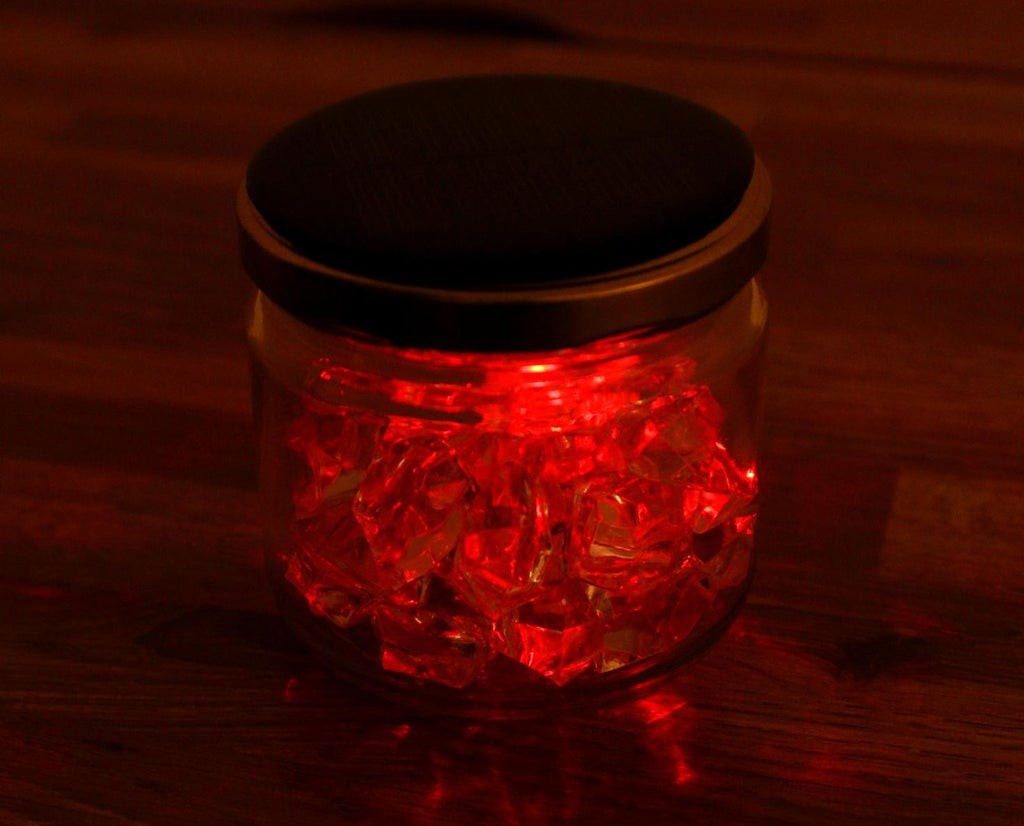
    Then close the glass jar lid and enjoy the slow and fast color-changing rainbow effect.

    The acrylic pebble scattered the light in different directions which looks very attractive.

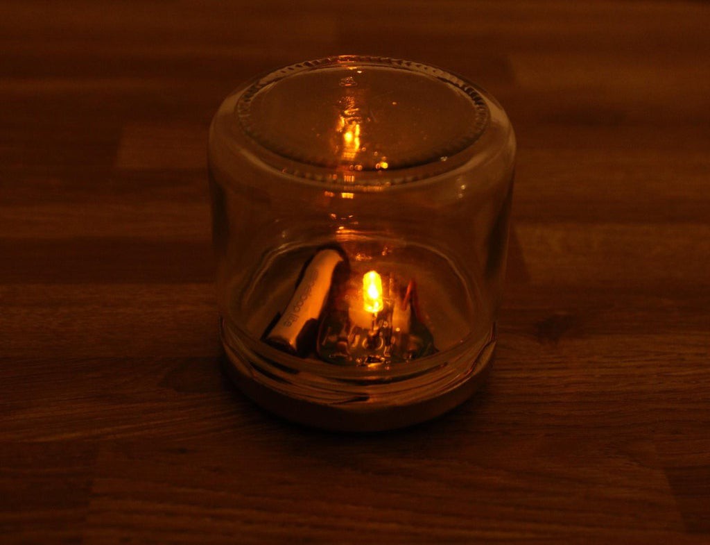
    3. Candle Flickering LED:

    Insert a candle flickering LED into the female header in the PCB.

    Close the lid, and see the flickering effect.

    Then I have added the acrylic pebbles, to get the more attractive light effect.

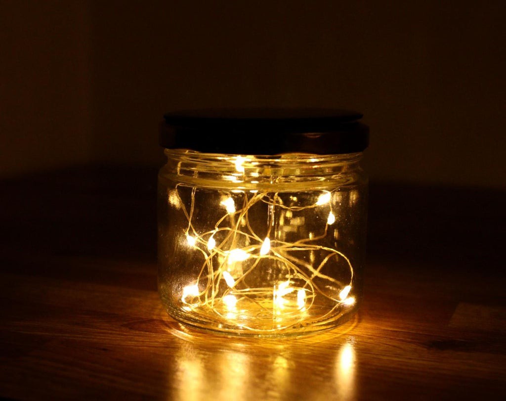
    4. Fairy String Light :

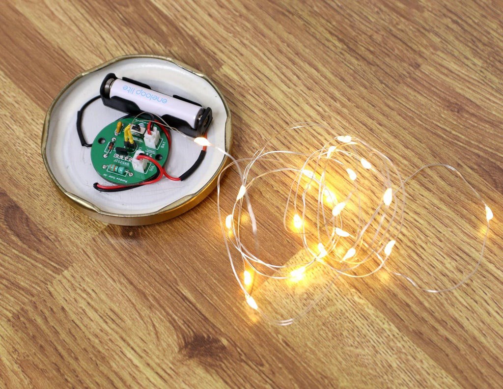
    Initially, I was not sure, whether the PCB will support a fairy string light or not. But when I tested it, I was really amazed that it works with charm. But I will recommend you not use too long a string, because it may exceed the current handling capability of the IC QX5252F.

    First I cut the fairy string light from the battery box. Then stripped out the insulation from the terminal wires.

    Then insert it into the female header to connect the LED. Place the string light inside the Jar and it's done.

    You can make a few similar jars and place them in your garden or lawn. Now enjoy your new solar jar.

  • Testing

    Open Green Energy08/07/2021 at 19:09 0 comments

    To test the lamp, cover the solar panel with your palm, the LED should glow. If the LED lights up, then the circuit is working perfectly.

    Before using the lamp, it is recommended to charge the battery in bright sunlight.

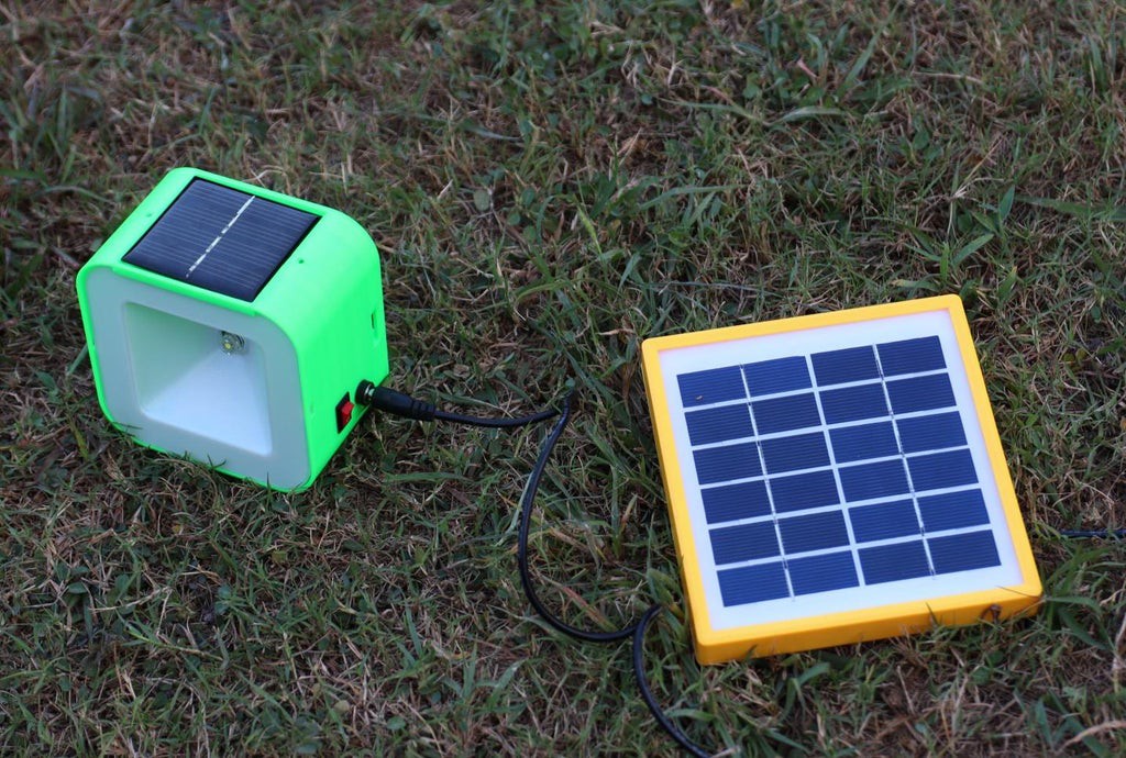
    You can place the lamp outside or you can keep the lamp inside and use an external solar panel (4 to 5V) to charge the lamp.

    Hope my solar light bulb will give light to many rural people around the globe.

  • PCB Design With Color Changing LED

    Open Green Energy08/01/2021 at 06:59 0 comments

    I have designed a custom PCB for this project. You can download the Gerber Files from PCBWay

  • Driving a Color Changing LED

    Open Green Energy07/31/2021 at 19:39 0 comments

    In the reference circuit diagram, the configuration is powerful enough to drive a white LED. But if you connect an RGB LED, instead of white you will notice that the RGB LED lights up however it doesn’t cycle through red green blue color.

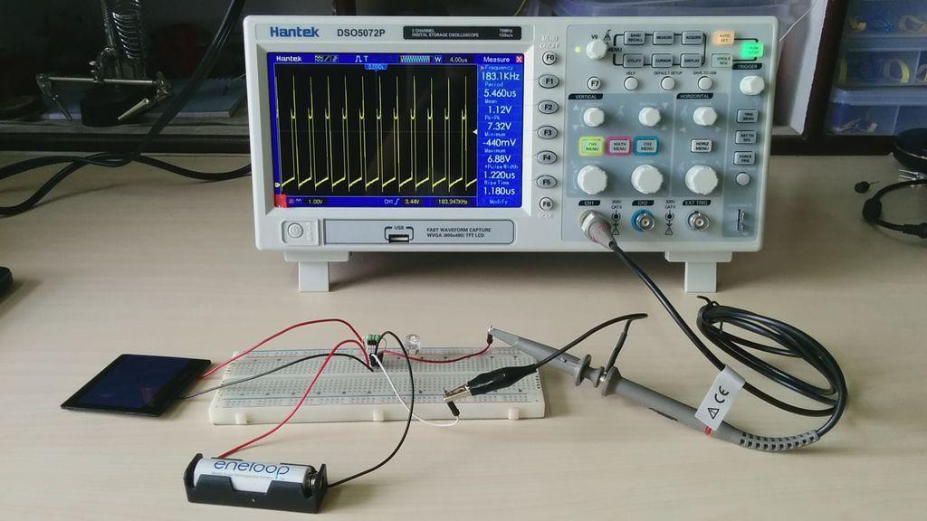
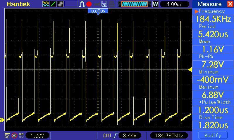
    The circuit is not working because the output from the circuit is not a steady DC output rather it is a high-frequency pulsating signal. In my breadboard prototype with only one LED, the configuration oscillates near 184.5KHz (see the image).

    How to fix this Issue?

    To fix this you need to add a buffer circuit at the output.

    The buffer circuit is just a diode ( 1N4148 ) and a capacitor (10nF ) at the output before connecting the LED. The diode keeps the capacitor charged when the pulsating signal goes to 0 volts.

    After adding the buffer circuit, you can notice that the RGB LED cycles through all 7 colors. Now you connect the oscilloscope at the LED terminal, the output is DC current with a little amount of ripple signal which is adequate for driving the RGB LED.

  • Printing the Enclosure

    Open Green Energy07/31/2021 at 19:31 0 comments

    I have used my Creality CR-10 Mini printer and 1.75 mm Green and White PLA filaments to print the parts. It took me about 5 hours to print the main body and around 2 hours to print the front reflector.

    My settings are:

    1. Print Speed: 60 mm/s

    2. Layer Height: 0.2mm ( 0.3 also works well)

    3. Fill Density: 25>#/p###

    4. Extruder Temperature: 200 deg C

    5. Bed Temp: 60 deg C

  • 3D Printed Enclosure Design

    Open Green Energy07/31/2021 at 19:30 0 comments

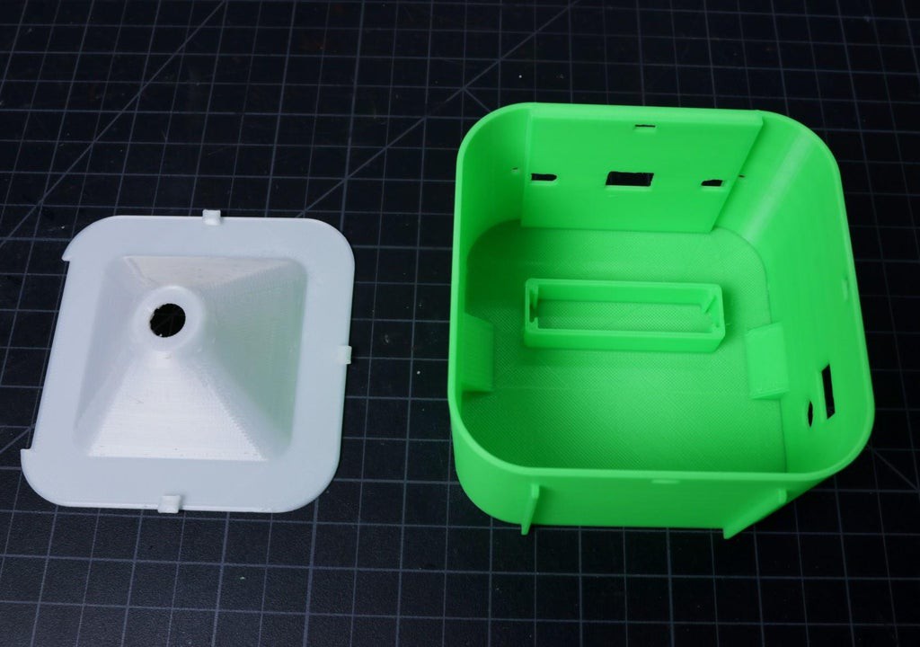
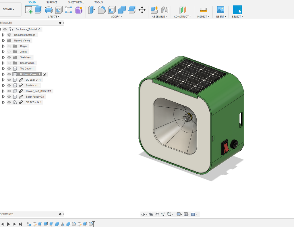
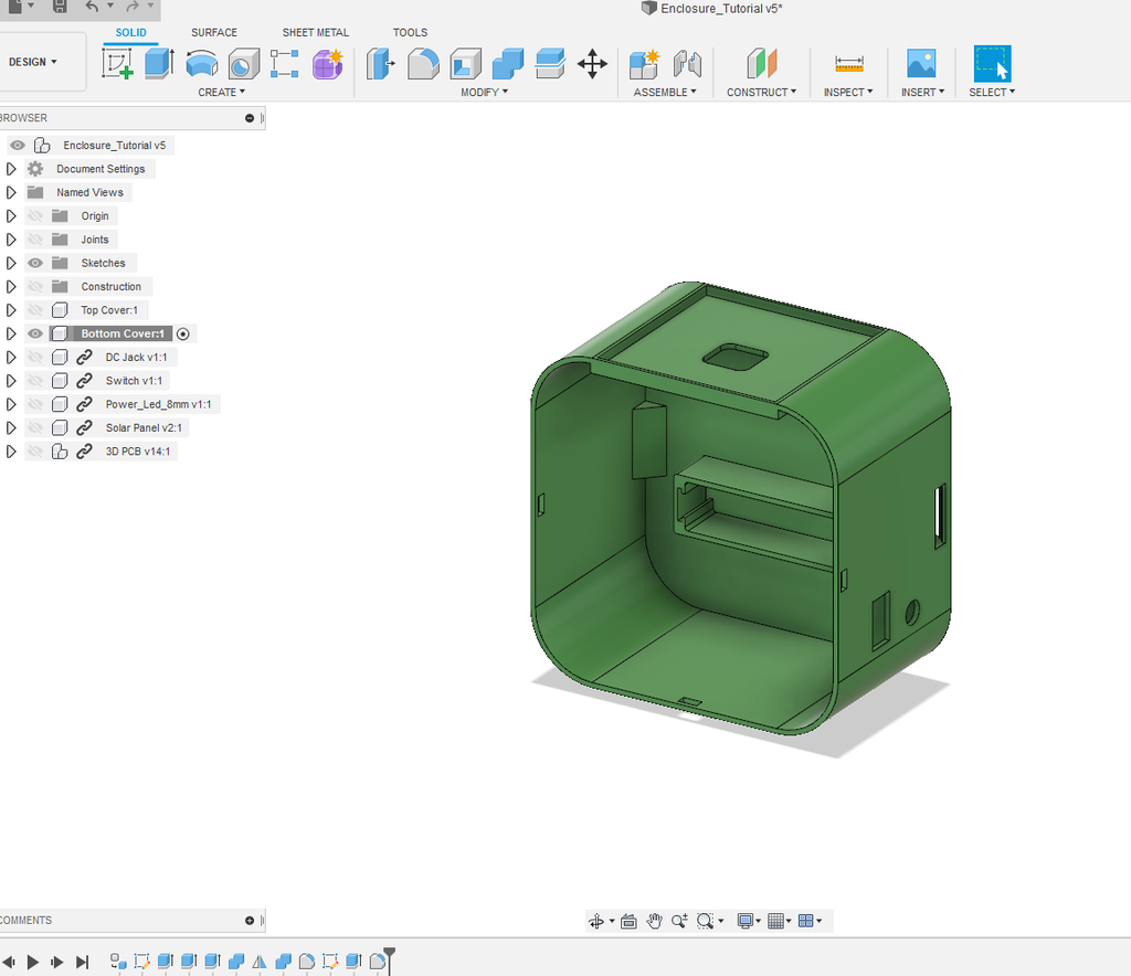
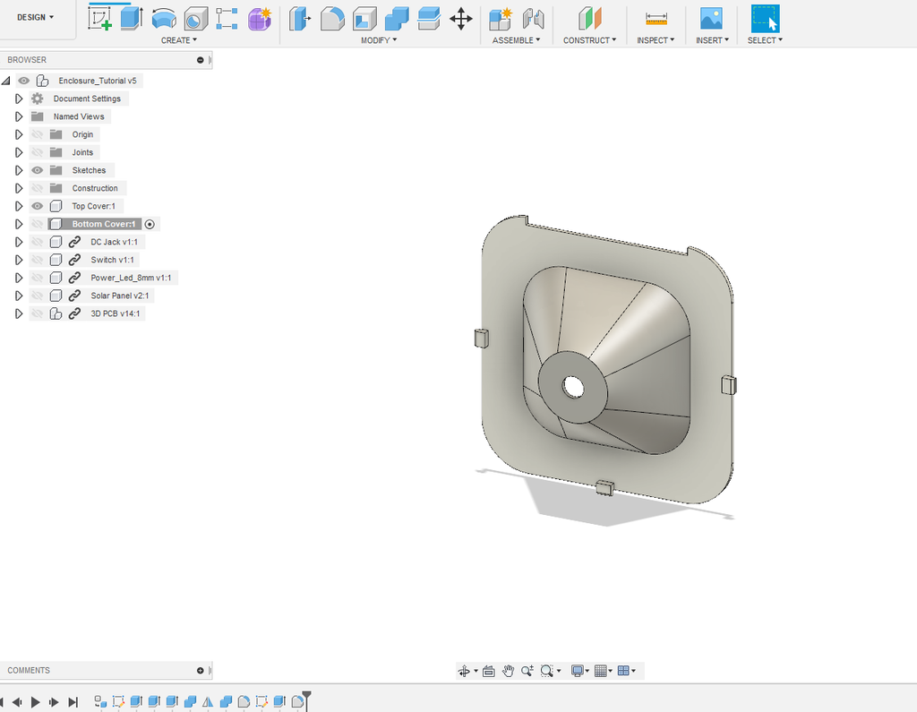
    To give a nice commercial product look, my friend " VARUN" has designed this enclosure for this project. He used Autodesk Fusion 360 to design the enclosure.

    The enclosure has two parts:

    1. Main Body

    2. Front Cover

    The Main Body is basically designed to fit all the components including the battery. The front cover is to covers up the main body and serves as a reflector to spread the light from the LED.

    Download the.STL files from Thingiverse.

  • PCB Design

    Open Green Energy07/31/2021 at 19:26 0 comments

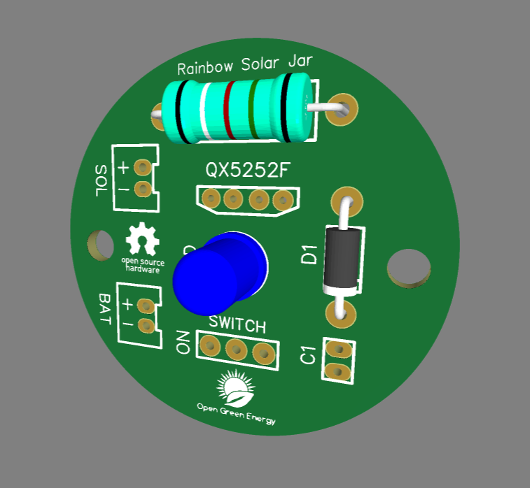
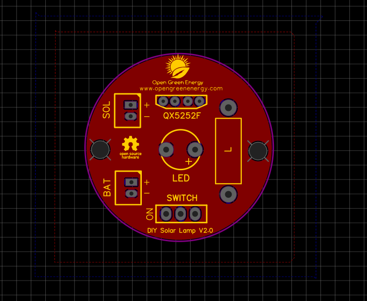
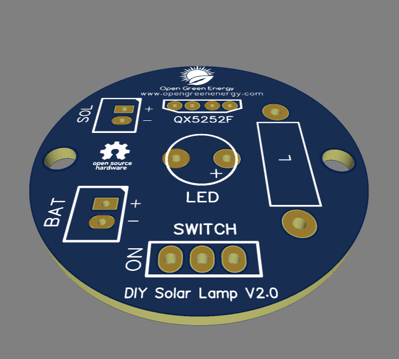
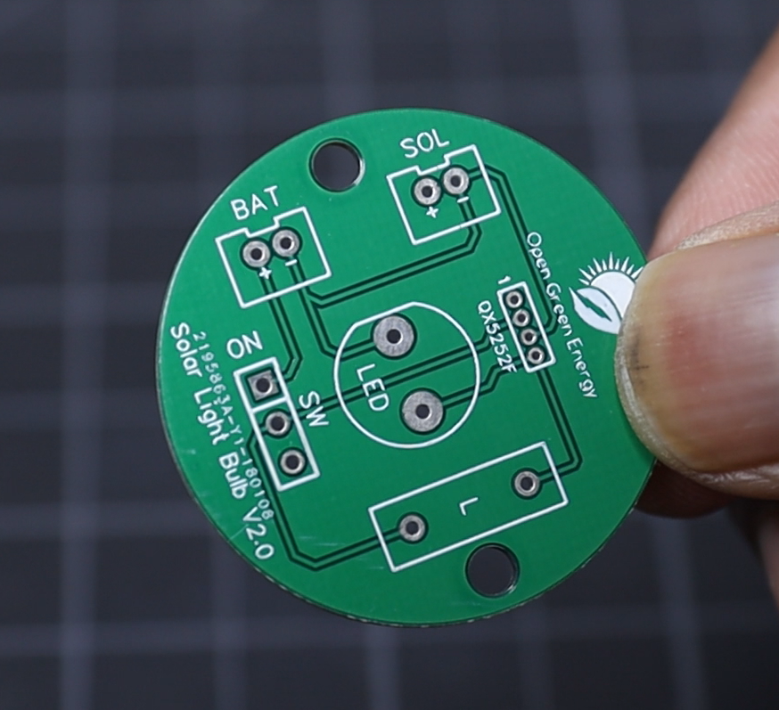
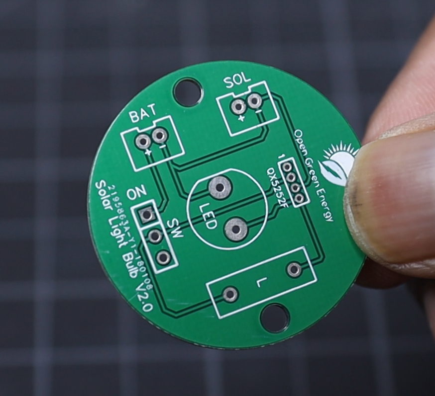
    I have drawn the schematic by using EasyEDA online software after that switched to the PCB layout.

    I have designed a circular board as shown in the above picture.

    After designing the board, I have ordered the PCB for prototyping from PCBWay.

  • Output Waveform and Observation

    Open Green Energy07/31/2021 at 18:53 0 comments

    To check the performance of the circuit, remove the LED and hook up the oscilloscope probes.

    You will observe that the output is not a steady DC voltage rather it fluctuates rapidly. In my case, the frequency is around 184.5 kHz. The peak to peak voltage is nearly 7.28 V and the average value is around 1.0 to 1.20V.

    Note: If you try to measure the voltage by a normal multimeter, it will show near to your battery voltage.Because your meters only measure the average value of a fluctuating voltage.

  • Breadboard Testing

    Open Green Energy07/31/2021 at 18:51 0 comments

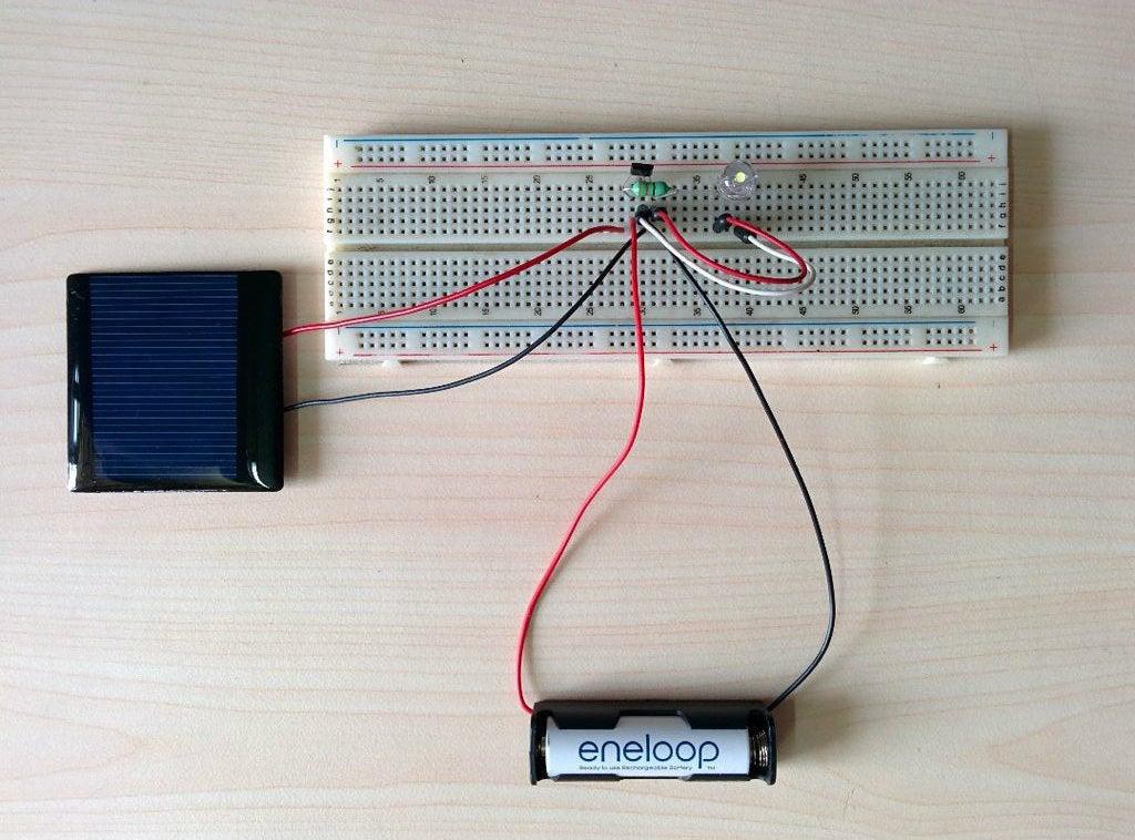
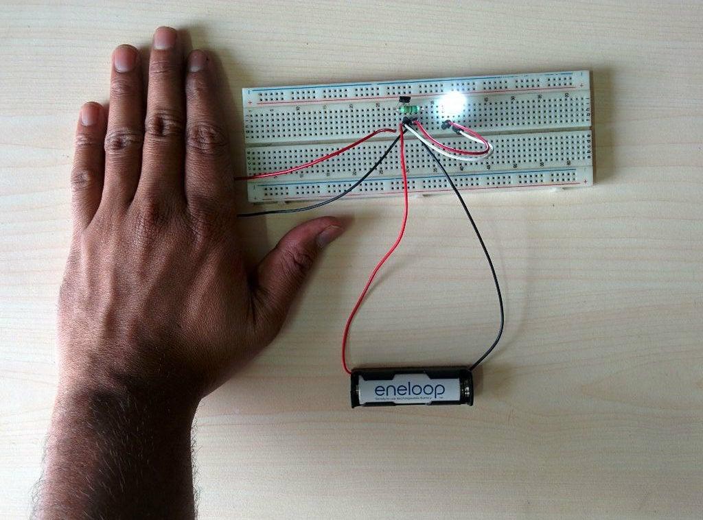
    Before finalizing the circuit, It is always a good idea to prototype the circuit on a breadboard. This lets you check to make sure that all of your components are working perfectly.

    Make the circuit on your bread bard as per the schematic. The LED should not glow if the circuit is correct. To simulate the dark condition, cover the solar panel with your palm. Now the LED should glow.

  • Controller Selection

    Open Green Energy07/31/2021 at 18:47 0 comments

    The controller has two tasks

    1. Charging the Battery:

    Isolate the Solar Panel and Battery when the battery is fully charged and Isolate the load from the Battery when the battery voltage is low.

    2. Driving the LED:

    Capable to drive the selected LED ( ability to handle the required voltage and current ) i.e Boost the battery voltage ( 1.2V ) to LED operating voltage (3.2V) or higher

    Here we will use a cheap QX5252F IC as a controller.

    The main features are:

    1.Suitable for a single AA NiMh/NiCd battery

    2.Operating Voltage: 0.9V-1.5V

    3.Output current: 3mA-300mA ( Our requirement is 93.7mA )

    4.Integrated Schottky Diode

    5.High Efficiency up to 84>#/p###

    6.Low quiescent current: 17uA ( When the circuit is not working / standby )

    7.Only an external inductor is required for making the Circuit

View all 10 project logs

  • 1
    Solder the Components

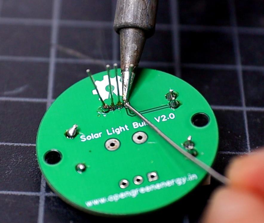
    It is good practice to solder the components according to their height. Solder the lesser height components first. You can follow the following steps to solder the components :

    1. Push the component legs through their holes, and turn the PCB on its back.

    2. Hold the tip of the soldering iron to the junction of the pad and the leg of the component.

    3. Feed solder into the joint so that it flows all around the lead and covers the pad. Once it has flowed all around, move the tip away.

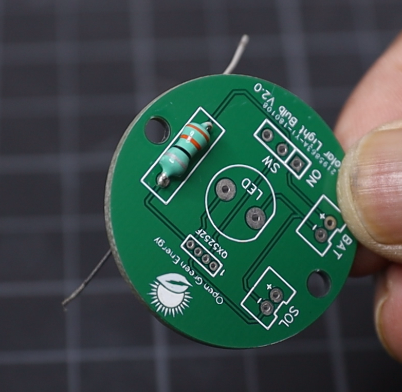
    First I have soldered the inductor, then the two JST connectors, and QX5252F.

  • 2
    Step 2

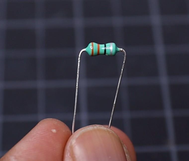
    Inductor comes in various packages, but here I have used an axial Inductor with value 33uH / 0.5W.

    First bend the two legs at a right angle, then push the legs through the holes named "L" on the PCB.

    Solder the inductor legs to the soldering pads on the PCB.

  • 3
    Solder the QX5252F

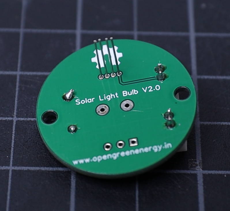
    The QX5252F comes in TO-94 package, the space between the adjacent legs are very small. So extra care must be taken during soldering. Otherwise, you will short the pins together.

    In my V2.0 PCB, I have used the TO-94 package footprint, but in V3.0 I have used a wider footprint so that less chance of short circuit between the two legs.

    Insert the QX5252F legs into the PCB holes, to insert correctly, number-1 is marked on the PCB. The pinout of the QX5252F chip is shown above.

View all 8 instructions

Enjoy this project?

Share

Discussions

Similar Projects

Does this project spark your interest?

Become a member to follow this project and never miss any updates