-
1Solder the Components
![]()
It is good practice to solder the components according to their height. Solder the lesser height components first. You can follow the following steps to solder the components :
1. Push the component legs through their holes, and turn the PCB on its back.
2. Hold the tip of the soldering iron to the junction of the pad and the leg of the component.
3. Feed solder into the joint so that it flows all around the lead and covers the pad. Once it has flowed all around, move the tip away.
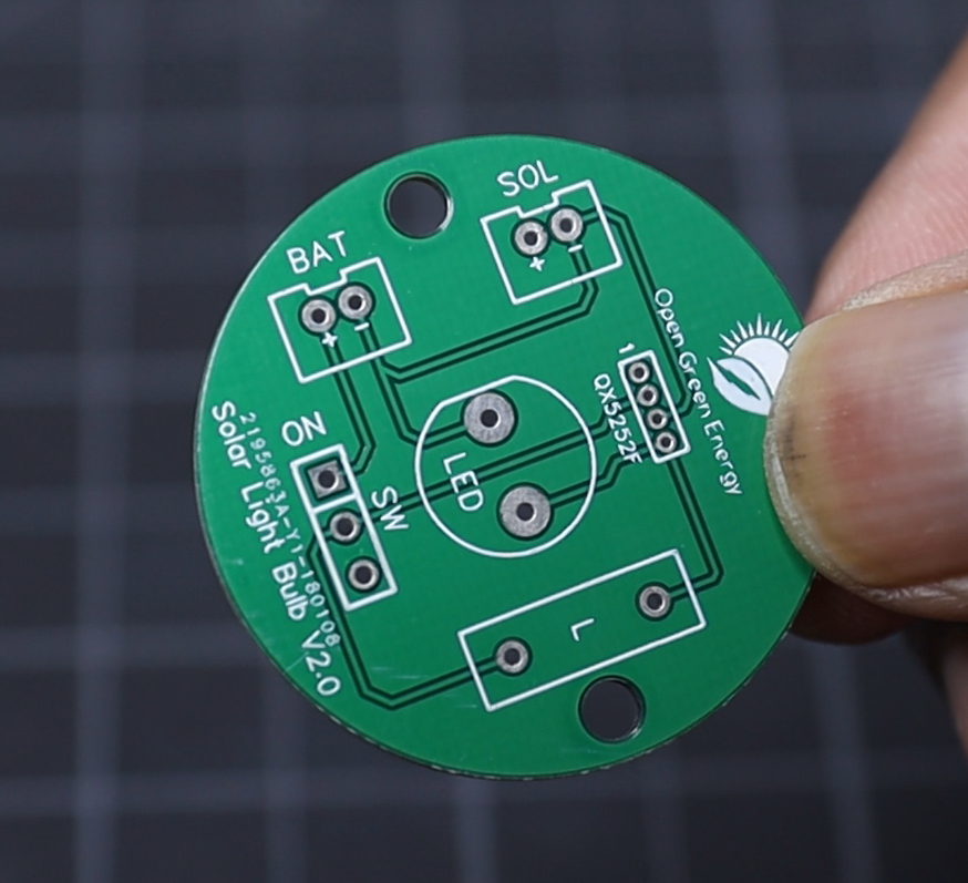
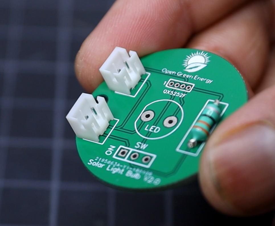
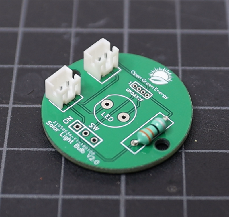
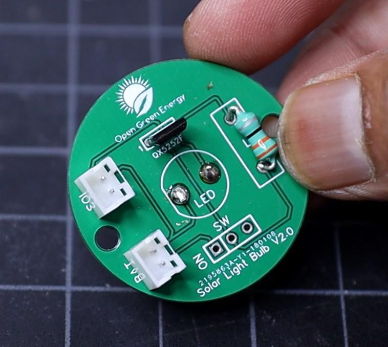
First I have soldered the inductor, then the two JST connectors, and QX5252F.
-
2Step 2
![]()
![]()
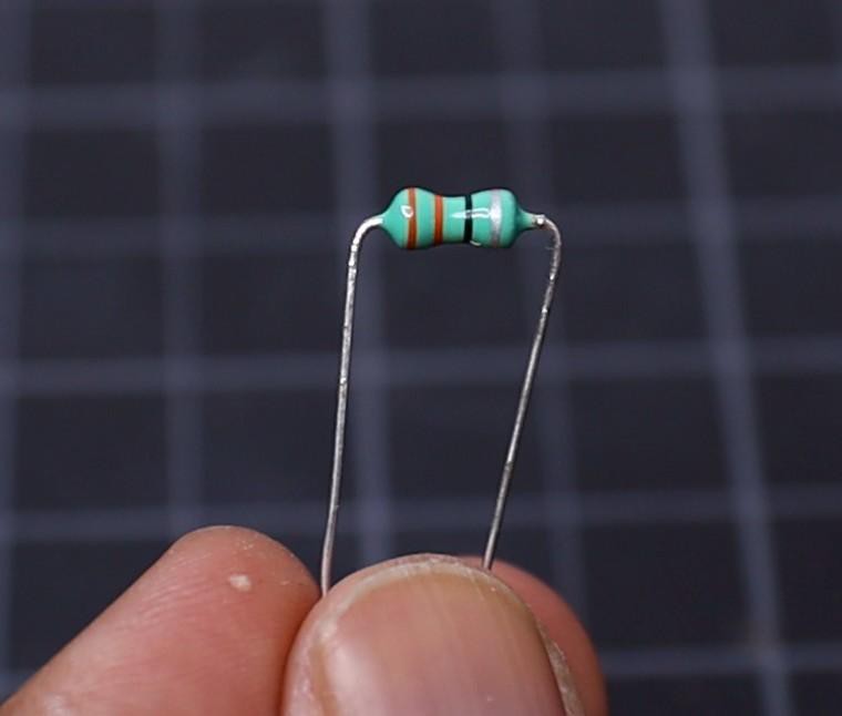
Inductor comes in various packages, but here I have used an axial Inductor with value 33uH / 0.5W.
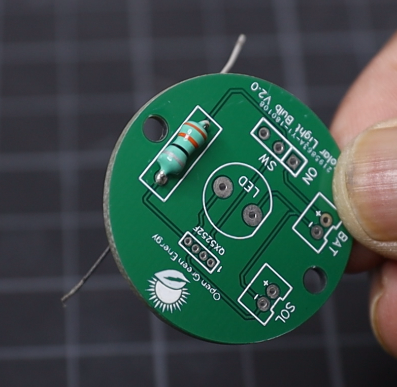
First bend the two legs at a right angle, then push the legs through the holes named "L" on the PCB.
Solder the inductor legs to the soldering pads on the PCB.
-
3Solder the QX5252F
![]()
![]()
![]()
![]()
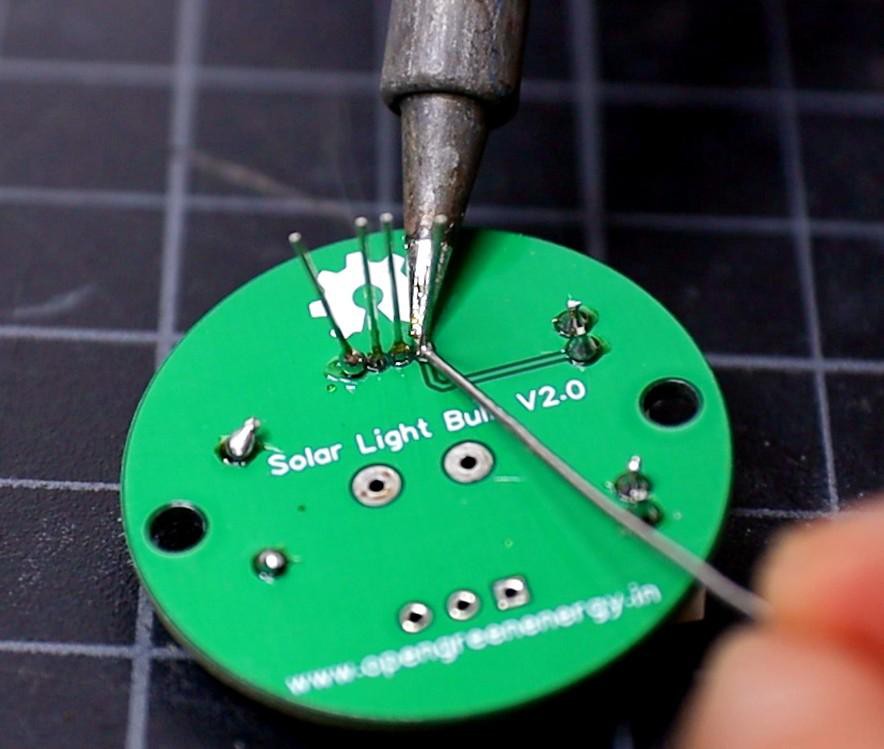
The QX5252F comes in TO-94 package, the space between the adjacent legs are very small. So extra care must be taken during soldering. Otherwise, you will short the pins together.
In my V2.0 PCB, I have used the TO-94 package footprint, but in V3.0 I have used a wider footprint so that less chance of short circuit between the two legs.
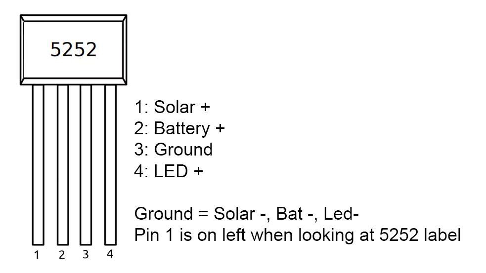
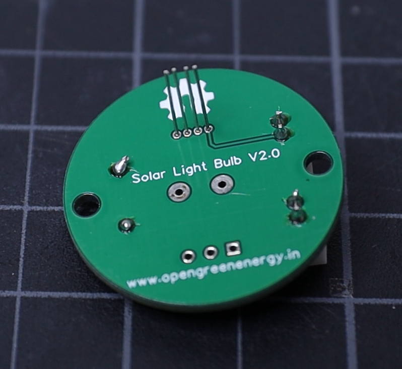
Insert the QX5252F legs into the PCB holes, to insert correctly, number-1 is marked on the PCB. The pinout of the QX5252F chip is shown above.
-
4Solder the JST Connectors
![]()
![]()
![]()
Two JST connectors are used for connecting the terminal wires from the battery and solar panel.
Here I have used JST 2.0 PH, during buying be sure you are selecting the right components.
Insert the two JST connectors into the holes named "SOL" and "BAT", then solder them.
Before soldering, be sure that the connectors are inserted correctly ( polarity is correct ).
-
5Solder the LED
![]()
![]()
![]()
![]()
![]()
![]()
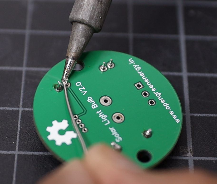
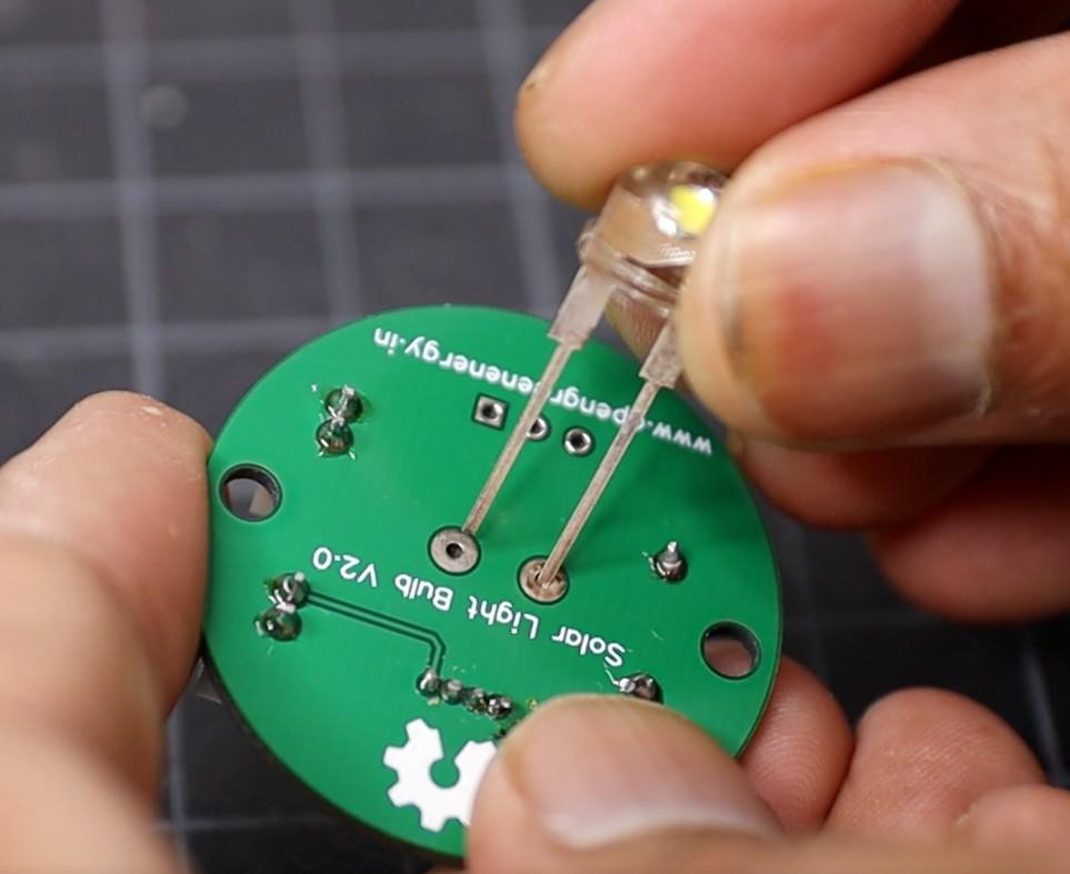
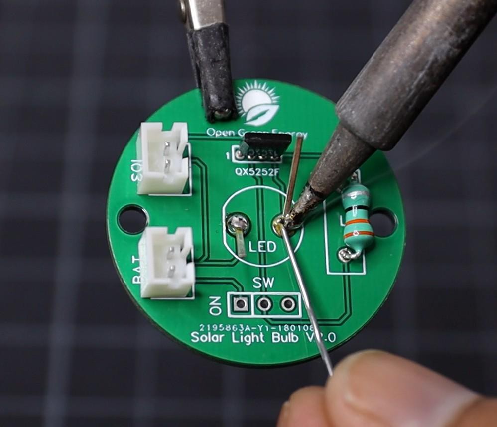
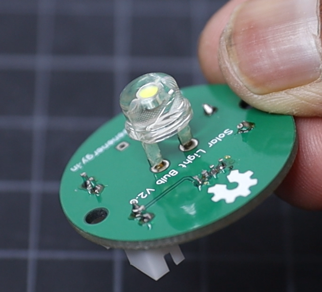
The LED used in this project is an 8mm / 0.5W straw hat type.
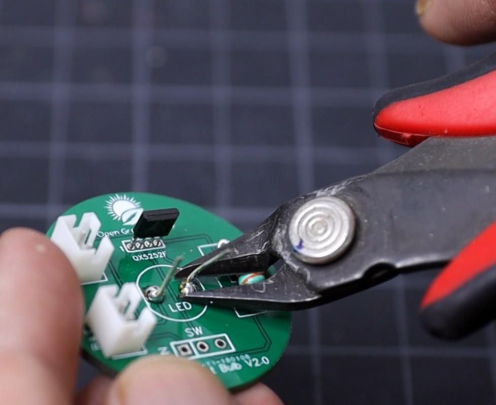
I have soldered the LED on the backside of the PCB. The reason for soldering the LED on the backside is that it will be easier to mount into the Front Reflector. But if you are not planning to use a 3D printed enclosure, you can solder the LED on the front side. Solder the LED with correct polarity, the longer leg of the LED is always positive terminal. Then trim the extra legs by using a nipper.
-
6Prepare the External Components
![]()
The external components are Solar Panel, DC Jack, battery spring plates, and rocker switch.
First, solder the JST connector terminal wire to the solar panel. The red wire will be connected to the positive and the black wire to the negative terminal.
Similarly, connect another JST connector to the two battery contact plates. The spring shape contact is the negative terminal.
At last, connect terminal wires to the DC jack and rocker switch.
Note:
1. Apply a small amount of soldering flux before soldering.
2. Apply heat shrink tubing to the exposed soldering joints, to avoid any accidental short circuit.
-
7Preparing the Reflector
![]()
![]()
![]()
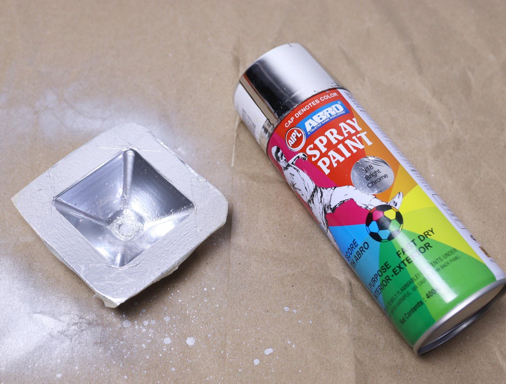
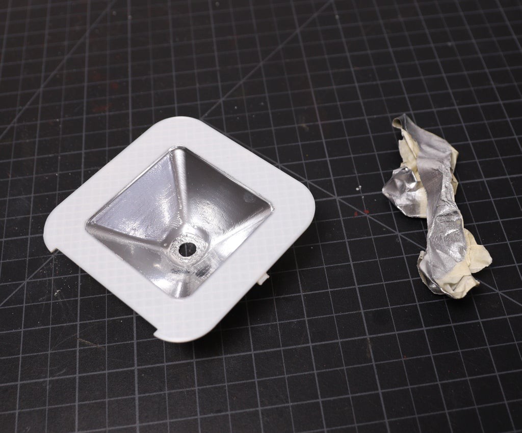
The reflector can be purchased directly from the market, but to reduce the cost, it is considered to be a part of the 3D printed enclosure. Only you have to apply a few coats of reflective spraypaint on the 3d printed enclosure.
Before applying the paint, cover the edges of the enclosure with masking tape, so that paint will be only applied to the reflector part.
Apply the spray paint over the enclosure surface. Then leave it for 10 -15 minutes to dry out. Repeat the same process 2 to 3 times (2-3 coats). It depends on you, how much smoothness you like.
After the final coat, leave it for 3-4 hours for complete drying.
Safety: Wear nose musk during the frosting. I will recommend doing it outside and well-ventilated space.
-
8Install the Components
![]()
![]()
![]()
![]()
![]()
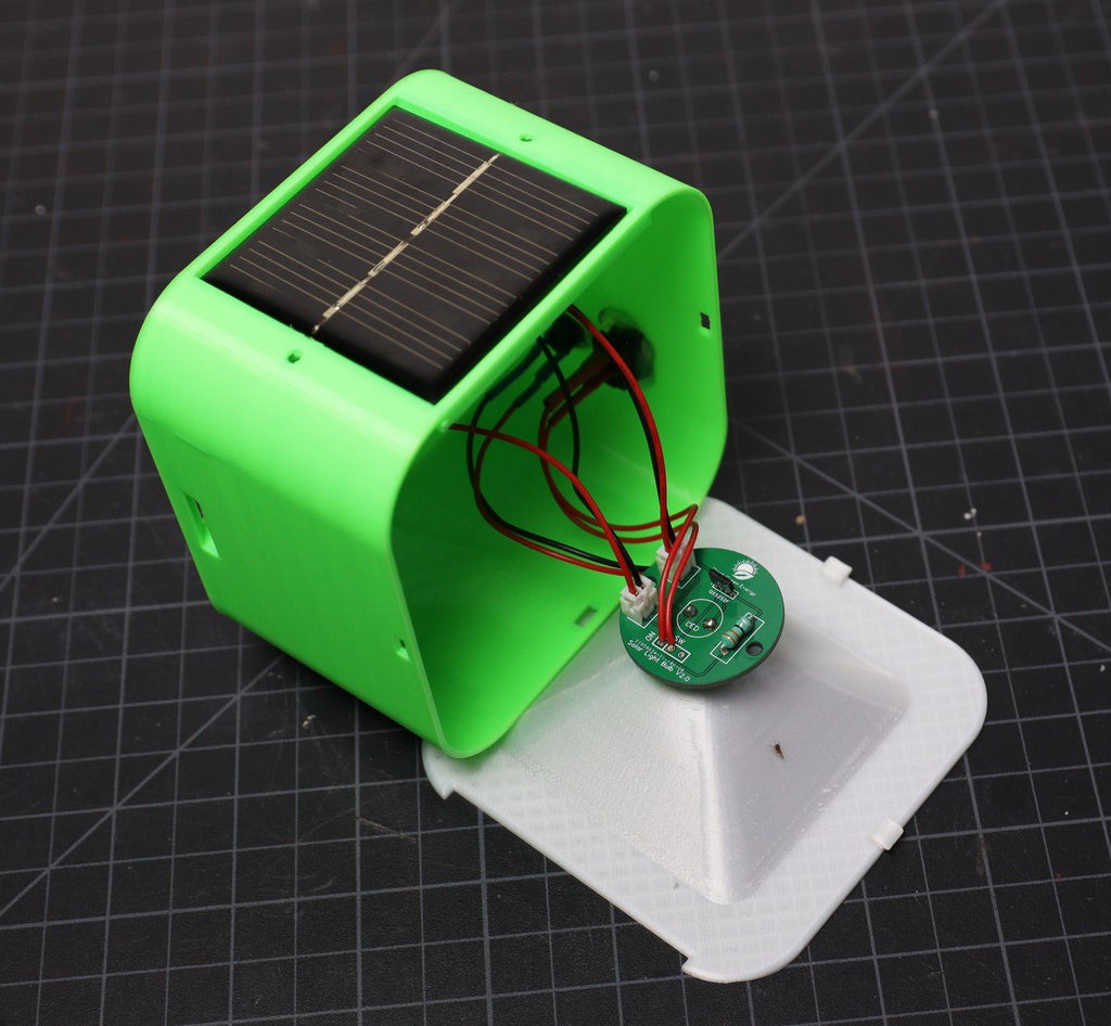
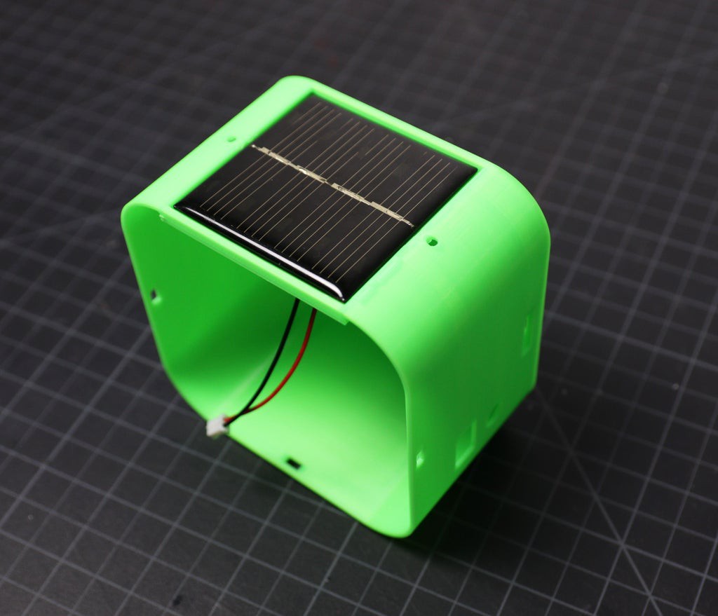
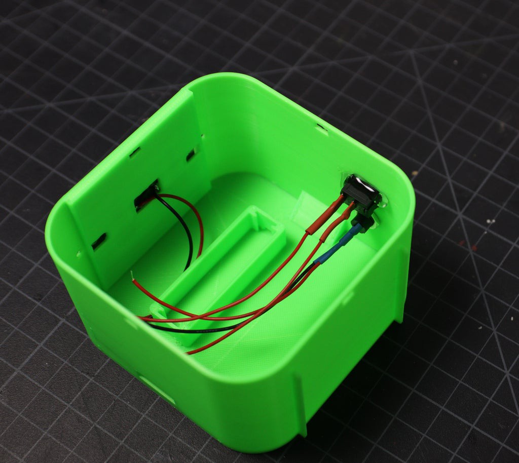
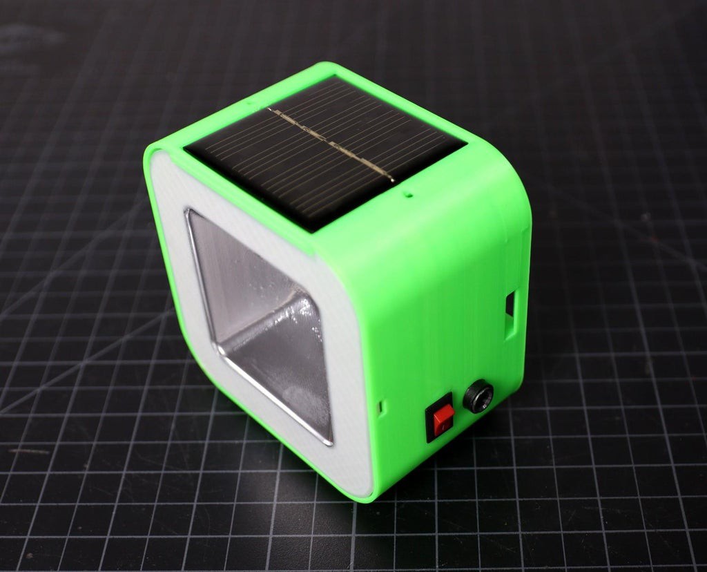
Install the Solar panel on the top of the enclosure. The solar panel that I used is 58 x58 mm. Then install the DC jack and rocker switch.
At last install the PCB on the front reflector. Use hot glue to fix all the components with the 3D printed enclosure. The enclosure is a snap-fit type, so we will not require additional mounting screws. Just align the tabs in the front reflector to the slots in the main body and then press it.
DIY SOLAR SOLAR LAMP
A low-cost solar lamp that can be used as a replacement for harmful kerosene lamps and a learning Kit for STEAM Education.
 Open Green Energy





Discussions
Become a Hackaday.io Member
Create an account to leave a comment. Already have an account? Log In.