shane.snipe
-
New connections
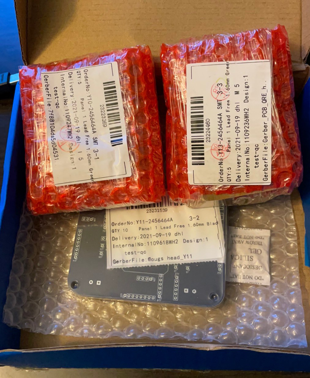
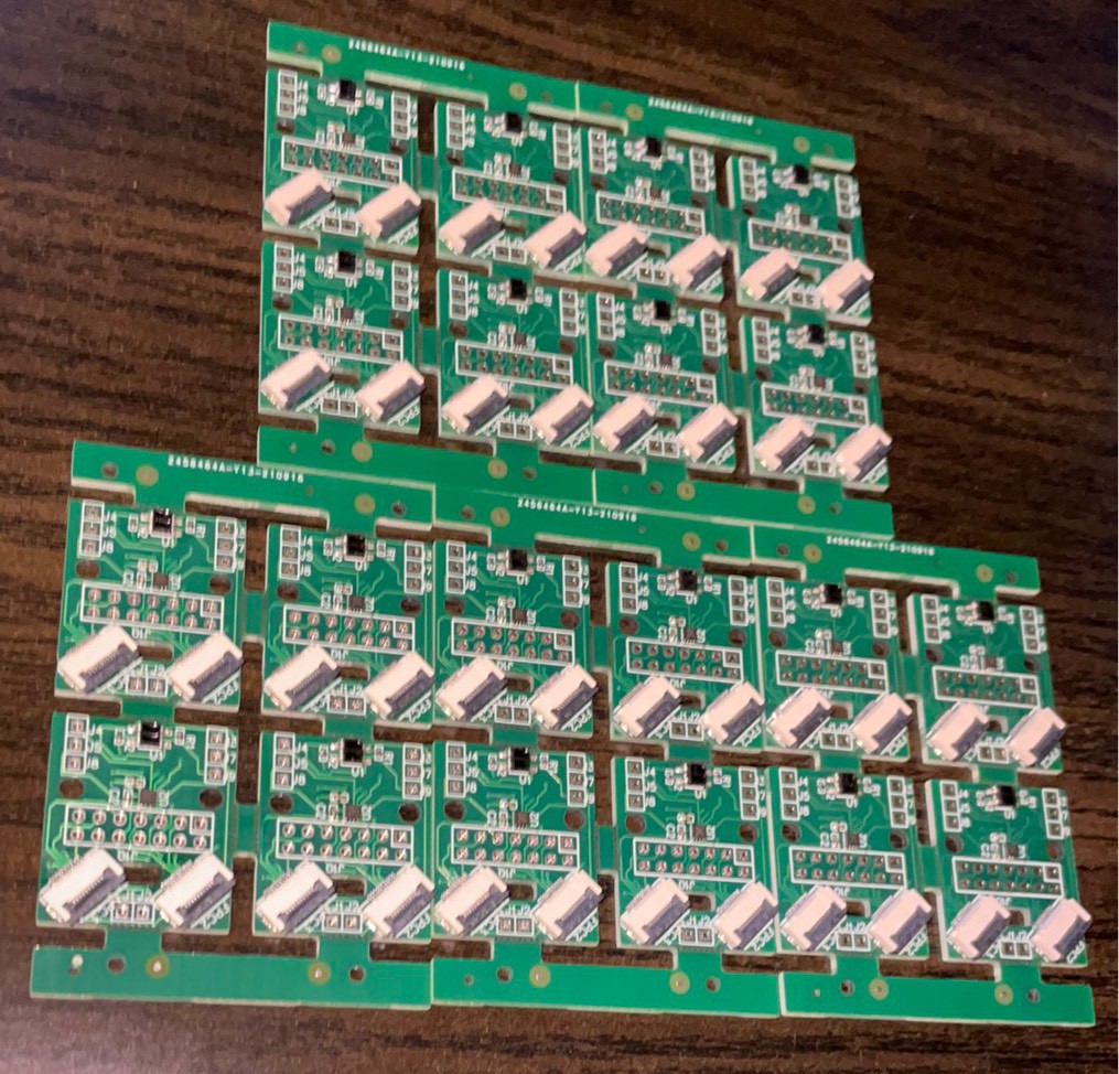
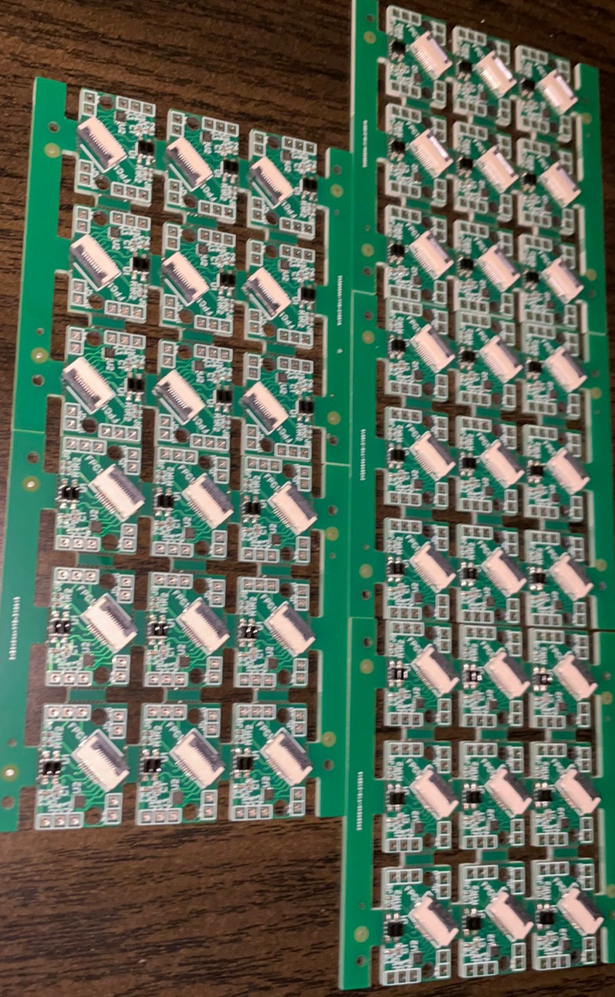
09/24/2021 at 23:27 • 0 commentsNew boards. Right on time.
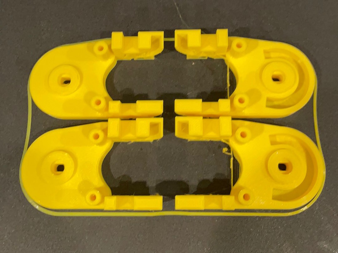
Hip boards
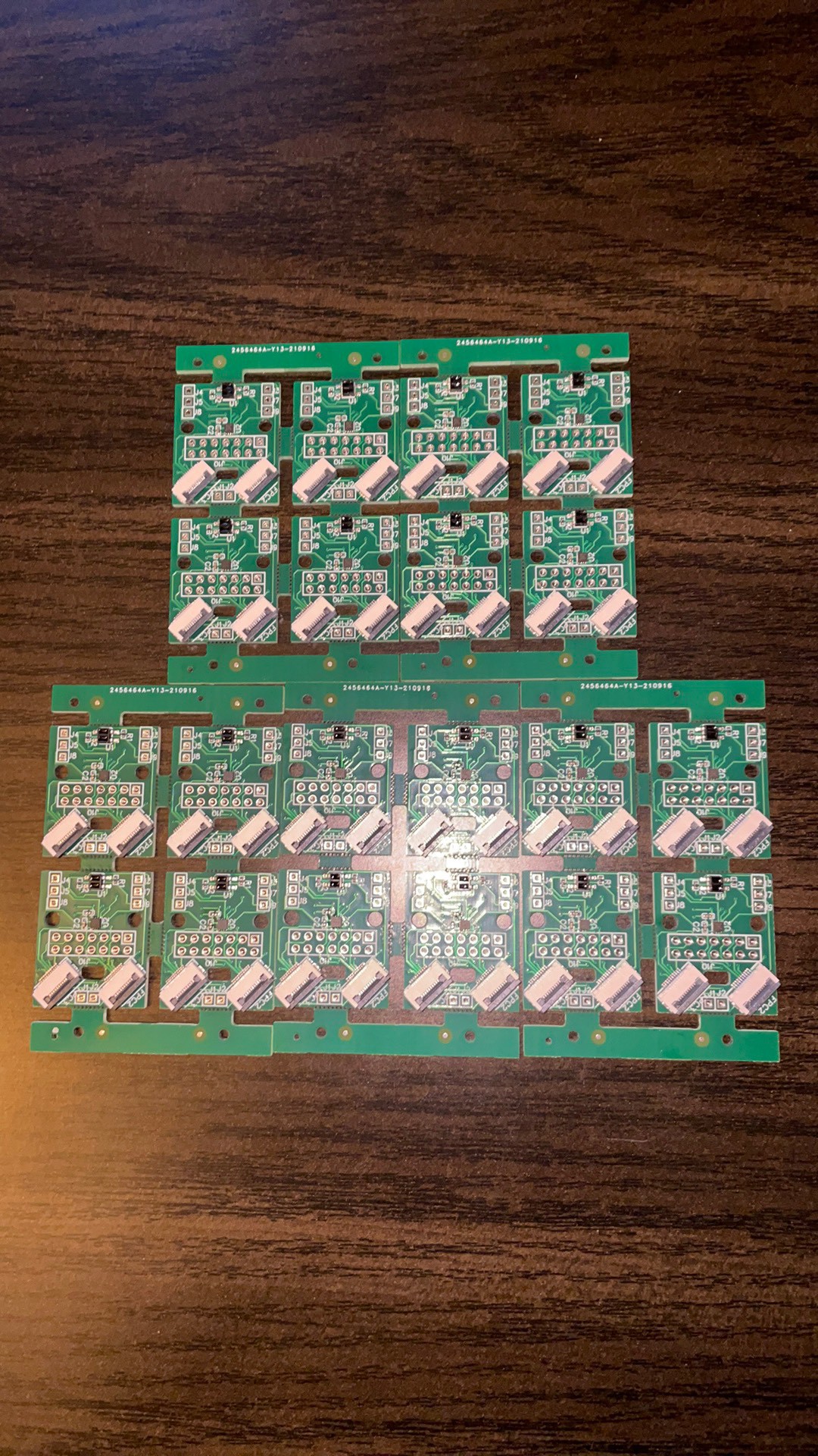
Hips
Holes line up.
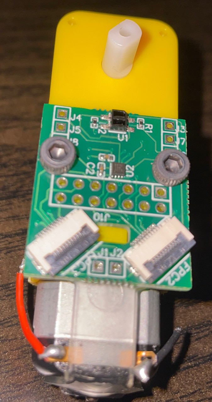
FFCs fit great.
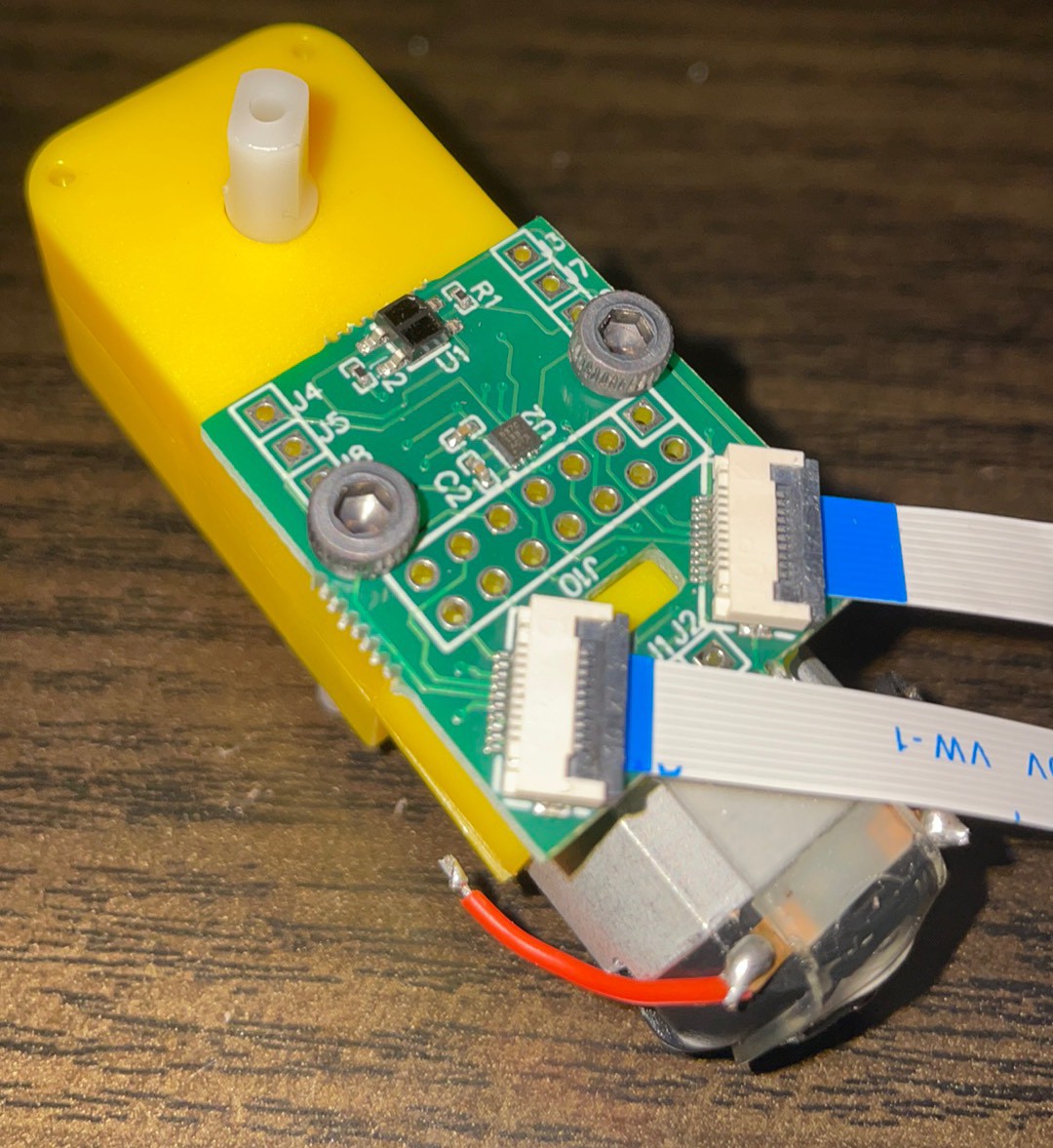
Tibula and Femur Sensor Boards
Connected
This time for the win
Holed all line up
Screws are a little tight on the pins
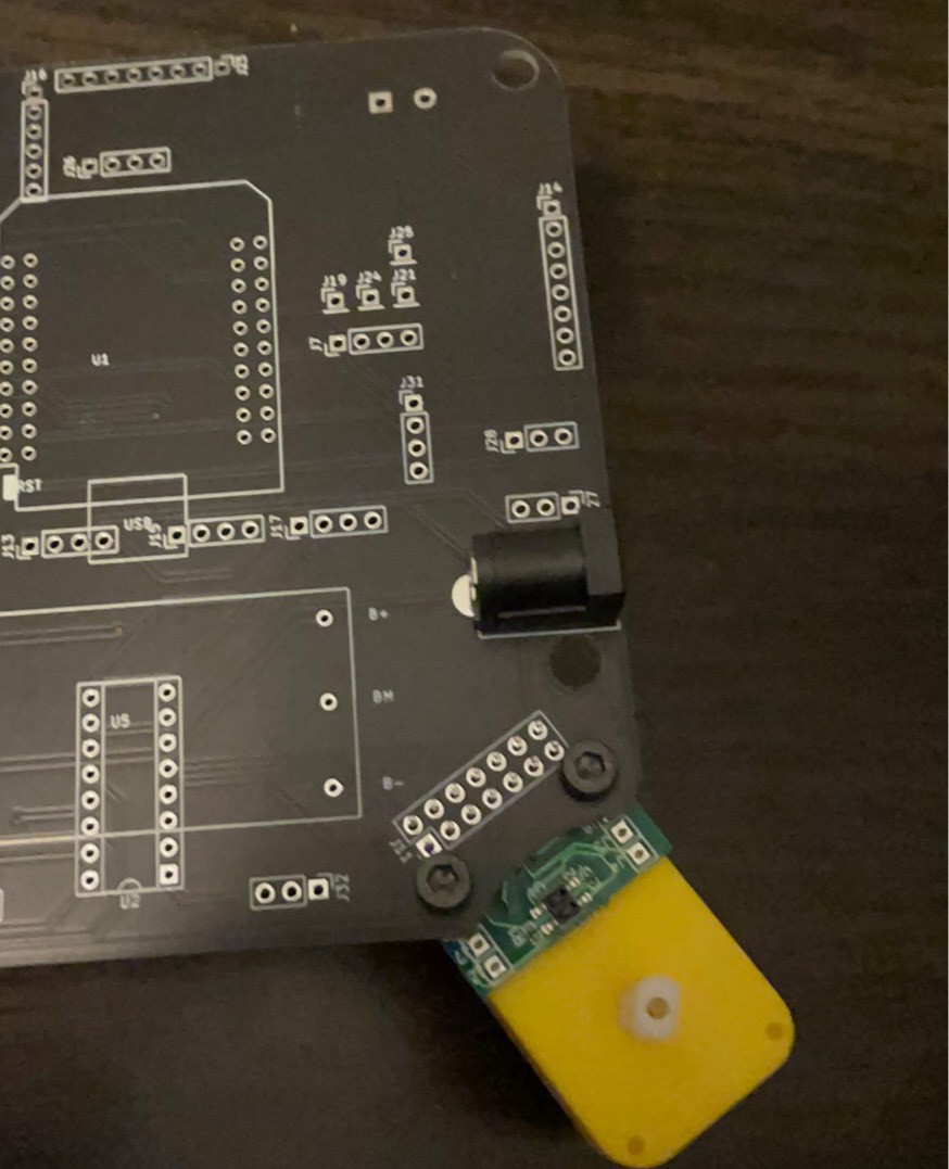
Power jack fits but I was thinking about it on the back. On the back it would have interfered with the motor so can we call it a happy accident?
Hips on the bed.
How to blink an led when it is on a robot. Step 1. Solder on the femur chip.
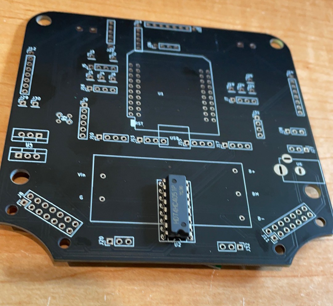
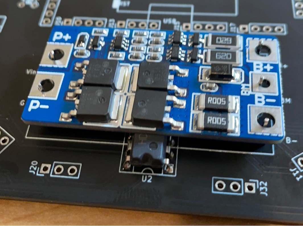
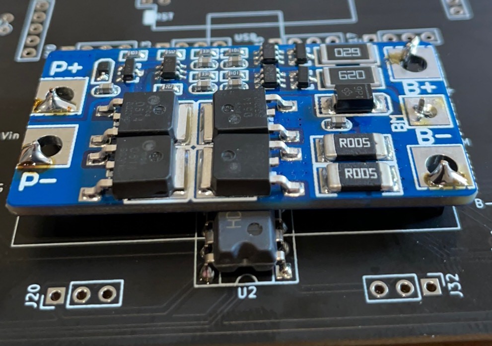
Solder pins on for the BMS.
Pins are swimming in the big holes. Bend them if necessary.
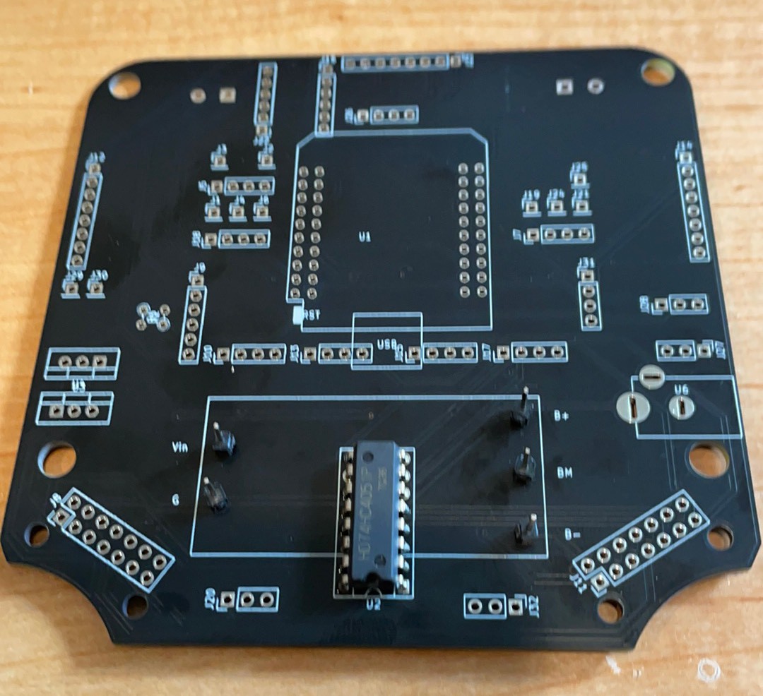
Femur made a nice stand to solder but some space would probably been a better idea.
Next solder on the headers for the ESP
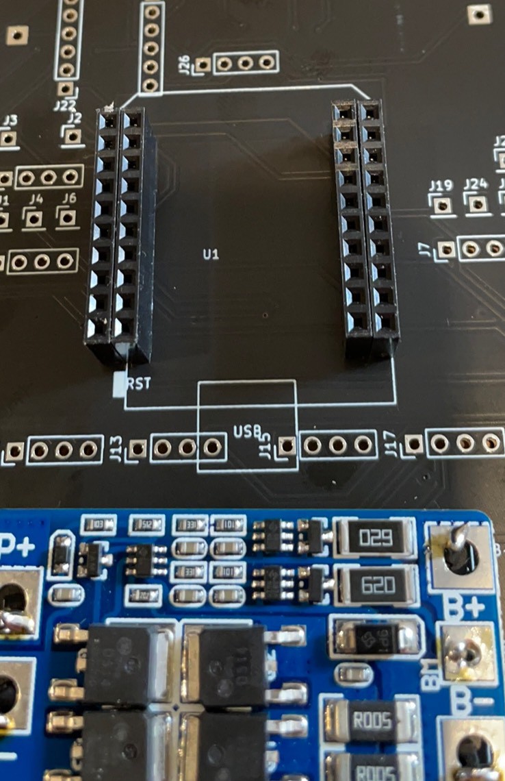
Solder headers on the back for easy removal of the legs.
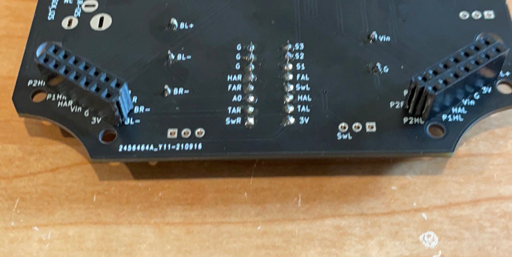
Solder the headers onto the hip boards.
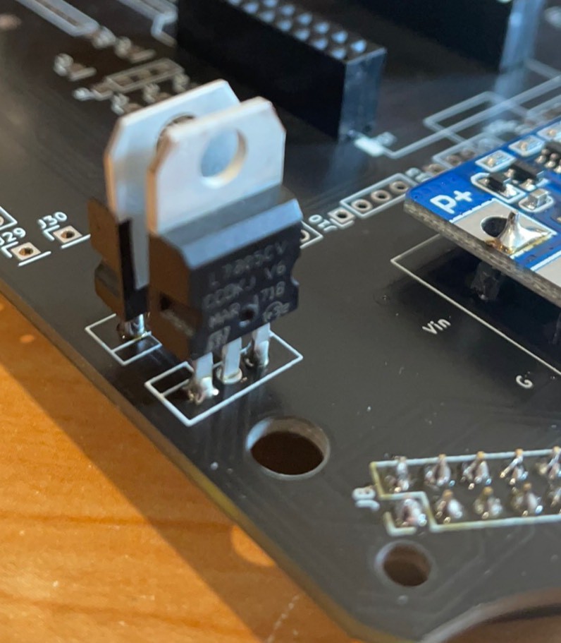
Solder the 7805 on the lower position for the 5V regulation and the 1117 above it back to back fir the 3V. Time to find out if my power circuit works.
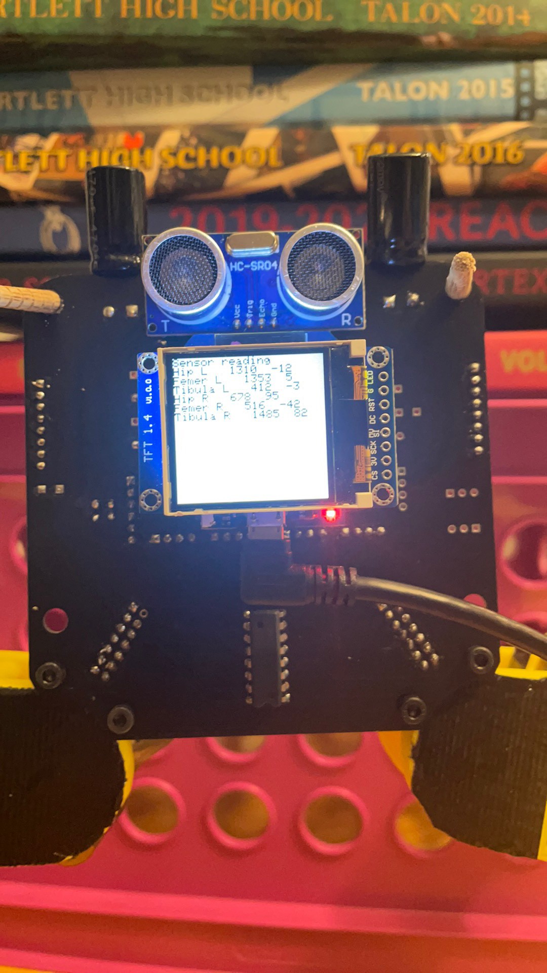
Sensor readings
-
Agility
09/16/2021 at 11:26 • 0 commentsI want robotics to be accessible. I want to to be able to hold a make and take class at our makerspace and have the class be able to assemble the robot in an hour. Well this week I had to admit the present design was not going to get there.
I worked hard on soldering up the PCBs to the flexes and if the wind was blowing the right way, I might be able to do it. More often then not, I tore a pad of the flex and I had to start all over on that leg. Or I had a trace break when I was folding the flex and now one of the encoders could not get signal. I figured it could have been improved through better and better flex design but this was hitting me in two places. 1st, the flex circuits were expensive and 2nd they were hard to assemble. It was really going against the key tenet of the project which was accessibility. The final straw came when Doug worked really hard on assembling a bot and despite having everything work as a flex, once he screwed the 3D printed parts on and connected it to the body, he broke a bunch of the pads between the flex and the surface mount header and all that work that ended the parallel path of development. If the founder of a makerspace can not put my robot together, I know it is time for a redesign!
So we were considering options and he mentioned a ribbon cable. The connectors for ribbon cables are too tall for this project but there are some very low profile FFC connectors! So I was off to redesign the robot to use FFC instead of custom flex circuits. They are available in any length on Digikey and super cheap on Ali express so that checked the accessibility box.
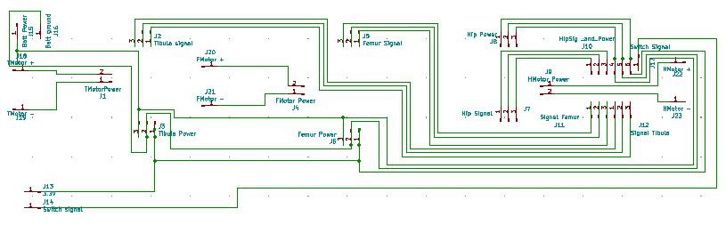
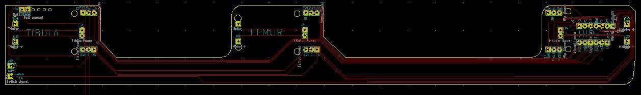
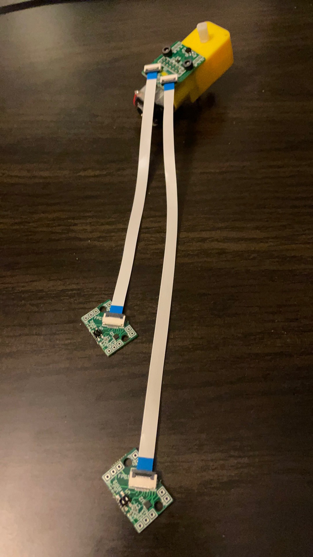
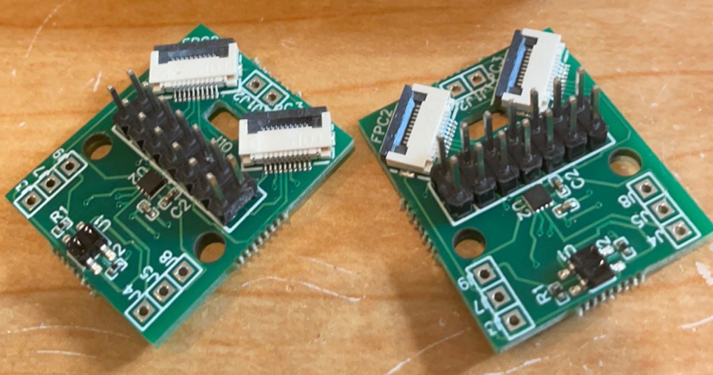
If that is all hard to imagine, here are some pictures to help.
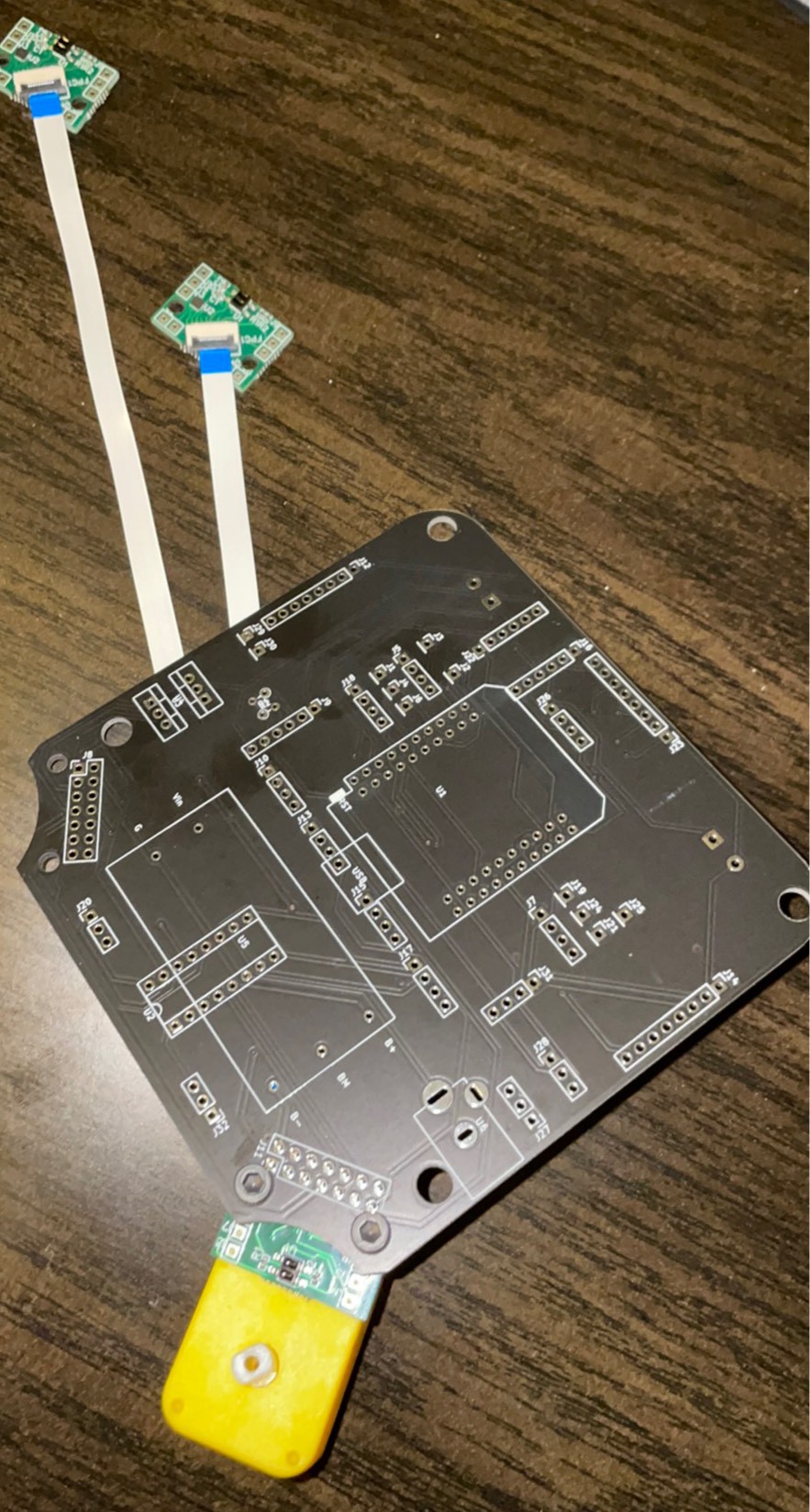
Here is the board that goes on the hip. It has a 14 pin header that connects to the main board and then two 10 pin ffc connectors the head off to the femur board and the tibula board.
I turned the header 90 degrees to make room for the FFC connectors. I am not sure if I have the angles right on the connectors but I only made 10 sets this time and I will revisit it after I have put some together.
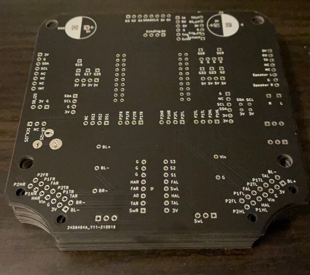
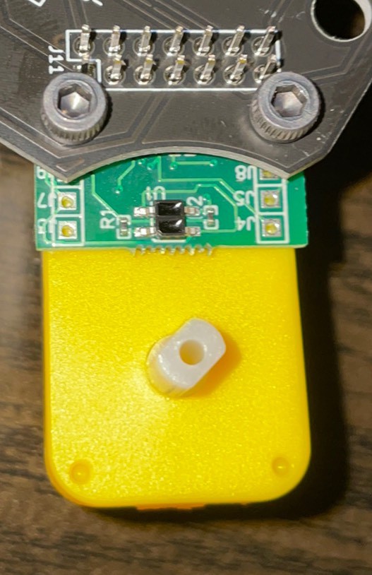
The headers at the top are just for debugging. The through holes J1 and J2 at the bottom are for motor wires. The double row of headers connect to the head board. There is a rectangular hole in the middle of the board to allow the board to sit better on the motor and accommodate the hook that holds the motor strap. It still will sit proud by the thickness of the motor strap but I think it will be acceptable. Otherwise I will make a 3D printed spacer again.
For the femur and tibula boards, I was able to make them common with each other. Both have the ability to connect to the battery and either battery connection will run to the main board through the FFCs and the 14 pin header. Here is the smaller board layout.
Ignore the headers as they will not be populated. I still have not figured out how to put a connected plated through hole without associating it with a header. If anyone knows, please leave me a note in the comments.
The battery will connect to J3 and J4. Which brings be to the battery management redesign. I really wanted the robot to be able to pop up but even with the 5V boost circuit, the motors did not have enough power to stand up from a splits position. What's the solution? - MORE POWER! - I considered putting back the battery boards I started with that had a adjustable voltage gain but it felt kludgy and I was not sure there would be enough current capacity. So I decide to connect the batteries in serial through a BMS on the head board. This takes the battery management out of the legs and gives me 7.2V. It also allows the motors to be charged with one 9V adapter that plugs into the main board.
Tomorrow I will describe the main board and all the changes but last night I ordered new head boards along with populated hip and femur/tibula board. By next Friday I should be cooking with gas! In the meantime I will do some documentation and touch up the mechanics.
-
Video proof!
09/05/2021 at 12:28 • 0 commentsWell since I have something that now moves, it is all just software. Twiddle a few bits and Cya is going to dance. There are some many things wrong with that statement. First hardware is never done, it is just done enough to get by and I do not think I am there. As for the bit twiddling, I need to back it up a bit and think about how I want to control Cya.
But first, a little glimpse of that I have been doing. I had mentioned a trestle which I imagined to be something to hold the robot up as it tries to walk. Well, two chopsticks, 6 yearbooks and one milk crate later, I had something workable.
If you look closely, you will see the encoder positions are read and displayed on the screen at the endpoints. This is one of the main reasons I wanted a screen. It so much easier that relying on the serial terminal for to understand the encoder limits.
So how to go from having a hardware platform that can move its joints and be aware of where they are to dancing? I guess the first point is to think about how to control the positions. Traditional robotics us inverse kinematics. This is basically where you know a position in space and then you calculate the angles of the joints to get there using trig. I think this is a non-starter for any non-roboticist so lets find a short-cut!
I am going to propose that movement is just stringing together a bunch of discrete positions and if the gap between the positions is small enough, you may not care how the robot moves to get there. So if the robot has of list of targeted positions and it moves from position to position, some reasonably compelling motion can be created.
Now, how can I make this easier. What if each joint has positions 1-100 with 1 being the smallest angle and 100 being the largest. With my low resolution encoder and joints with backlash, this is probably an appropriate resolution for the joints.
So what are the steps to get there.
1) Map the encoder output to 1-100 and display the joint position on the screen for each joint.
2) Manually move Cya's joints to the desired positions to make up the choregraphed movement. Record the sequence of positions.
3) Code the function that moves each joint to the desired positions.
4) Call the function to work through the array of points to make one cycle.
Stretch goal would be:
Take points from one robot and transfer them to another via ESP Now.
This seems simple and straight forward but it also is different from what I have seen other projects do. First of all, unless you have super high end servos, you do not have positional feedback available. In other words, you can not move the robot to a joint and record the position. You have to go back to the inverse kinematics. Another way to get at it is to use reinforcement learning to get to a set points. I was working with a team to do this but unless you can ignore inertia of the limbs, the math is too intense for model to work. This is why you see a bunch of stick legged robots. So on my team, the computation guys kept pushing the mechanical team to pull the weight and actuators out of the legs. However, I think the farther the weight is from the ground, the hard it is to make the robot balance so these are conflicting goals. Sacrificing physics so you can calculate something makes no sense so I went the opposite way on Cya and put the batteries as close to the ground as possible. This should make the robot more stable. We will see how it goes!
-
Leg assembly
08/31/2021 at 01:40 • 0 commentsHere is my attempt to document an assembly attempt. I was pretty happy with the way this much of it came together. The plastic assembly is supposed to be the easier part.
Assembled flex
![]()
Backside
![]()
Remove adhesive backing
![]() Monday morning quarterbacking this, I see although sticking it down makes the assembly a little easier, I is causing way more issues. Next run I will not stick it down until everything is together.
Monday morning quarterbacking this, I see although sticking it down makes the assembly a little easier, I is causing way more issues. Next run I will not stick it down until everything is together.Mount on motor
![]() I put a header under the board and came up through holes in the flex. The two pins on the right were great and it holds it to the flex because there are plated through holes to solder to before the board is put down. This is power to the circuit. The two pins on the left are for charging and are OK but a little tight into the foot housing. The two in the middle should be removed and replaced with just wires. I soldered to the pin headers I bent over here but then had a hard time putting them in the foot and getting the battery in the foot.
I put a header under the board and came up through holes in the flex. The two pins on the right were great and it holds it to the flex because there are plated through holes to solder to before the board is put down. This is power to the circuit. The two pins on the left are for charging and are OK but a little tight into the foot housing. The two in the middle should be removed and replaced with just wires. I soldered to the pin headers I bent over here but then had a hard time putting them in the foot and getting the battery in the foot. Stick down the flex
![]()
Mount in the foot
![]()
Check power.
![]()
Squeeze the battery in
![]()
All assembled
![]() The one off button has almost no room. It is a momentary switch but it needs to be pressed to get power to the circuit. Need to make the window bigger again. The board is not sitting well because the bent header pins that connect to the wires that go to the battery are wedged under the housing.
The one off button has almost no room. It is a momentary switch but it needs to be pressed to get power to the circuit. Need to make the window bigger again. The board is not sitting well because the bent header pins that connect to the wires that go to the battery are wedged under the housing.Cut off the tops of the motor
![]() The motors butt up top to top and the flex is in between. Cutting the tops give more room for the flex.
The motors butt up top to top and the flex is in between. Cutting the tops give more room for the flex.Add tibula
![]()
Screwing it together. Electric driver is a life saver.
![]()
Major Fail!!! Ripped the solder pads off the flex. Game over……
![]() Once the pads come off the flex, it is game over. I think if I go with a double sided flex, they might be more robust. I also might try a thicker flex in general. Lastly, I seem to have the most trouble when I put down the adhesive. There is no longer any give and things start to tear. Also the adhesive backing makes it less likely to tear as well.
Once the pads come off the flex, it is game over. I think if I go with a double sided flex, they might be more robust. I also might try a thicker flex in general. Lastly, I seem to have the most trouble when I put down the adhesive. There is no longer any give and things start to tear. Also the adhesive backing makes it less likely to tear as well.Another broken trace in the corner
![]()
Here is another example of a tear and you can see it cut through the trace. After this I turned on the battery and connected it to the head but no power went up so its back to the soldering iron.
-
Following Along at Home
08/30/2021 at 03:33 • 0 commentsI'm following along with Shane's build, but doing all the software/firmware in MicroPython. Here's where I am so far:
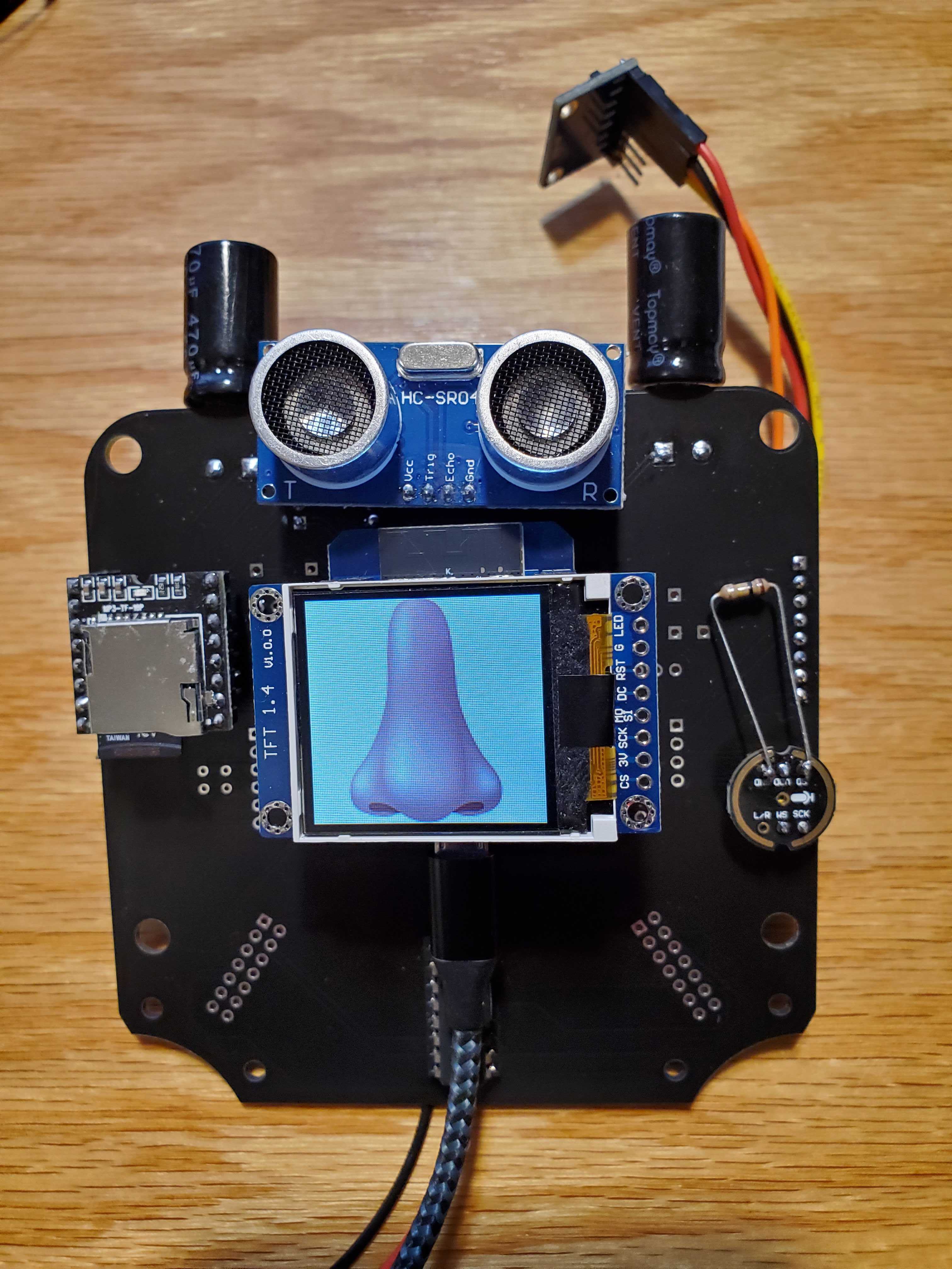
![]()
I've been able to get the mp3 player, the microphone, the accelerometer, the PCA9685 PWM board, the ultrasonic distance sensor, and the TFT display all to work using MicroPython. Next up is leg assembly and working through how to control the motors and react to the sensor values.
-
Opportunities!
08/29/2021 at 13:08 • 0 commentsAt work, in as slightly tongue in cheek way, we call issues opportunities. Opportunities for improvement and boy do I have them.
I thought RX talks to TX on the DF Player but apparently it is not the case. Need to flip these pins to work.
SCL and SDA are flipped on the Gyro board. Oops.
And running the Int pin from the Gyro to GPIO 4 on the ESP puts it into boot mode so the combination of these issues required surgery to remove the Gyro to get it to work.
Once I got to PCA9685 on the right way, at least I could read the sensors and control motors.
Last weekend I laid out the parts to take to Doug for our solder fest on Saturday. Strangely a half dozen parts are already changing.
![]()
Motors - I had been trying to used the 48:1 version because they were more common. I soldered up some flexes this week and tried them out but they just do not have the torque. I will need to use the less common 120:1 version. There are some inexpensive options on Ali Express but so far the Amazon options are scarce. I have bought out 2 vendors so far.
The shaft adapters next to the motors needed to have the shoulders a half mm shorter for ease of assembly. I did that yesterday and they are printing now. The Flex base, Hips and Tibia are unchanged. However, I did a major update yesterday on the feet.
I have moved the battery board to the ankle instead of under the foot. I also moved up the switch and put it on the back of the foot. This allowed me to remove 10mm from the height of the robot which should make it more stable. I added a boss so they snap together.
The switch was placed perfectly and battery fit well. The downside is the I had to make some "adjustments" to fit in the inductor on the battery board. Also I see there is a switch on the batter board with is no longer accessible. I am going to have to blow a bigger hole in the side of the foot.
![]()
I like the compactness of having the board on the ankle but the through hole to pad joint is not robust enough. I am going to have to put a pin through it. The MH-CD42 battery boards are awesome. They are compact, boost to 5V and have battery protection for charging. Here are some descriptions.
https://www.robotics.org.za/MH-CD42
https://techobsessed.net/tag/mh-cd42/
I got the new flex circuits in and the pads changed back to plated thru holes. This is what is on the Gerbers so I can not complain but last time they had pads which actually worked out pretty well. The motor terminal connects worked out pretty well. I opened up a NPTH next to the plated thru hole. I can connect the motors without wires now. The down side is I have had a couple of motors shorting under the sensor board because the solder for the blind connection comes together. This is what derailed by build this morning. I was supposed to be shooting video by now! I also have had some broken traces when I crease the flex. I may need to order it in a thicker vintage so it is more robust. My brother called me out as I said the flexes would make it more reliable and then I am struggling with them.
Test
![]()
On the bright side, I displayed the status of 6 sensors and 2 switches on the screen, I was able to run 4 of 6 motors and the motors that did not run were debugged to solder issues. I also determined I can print a full robot in one go on the Sovol SV02..
![]()
Too bad I have to blow out the hole in the foot. It only takes 28 hours!
So my updated punch list is as follows:
1) Resolder two more flexes and attach motors
2) Run this sketch again to confirm function.
3) Blow out hole in the ankle for the battery board. Print.
4) Design and print the flexible sole to cover the bottom of the foot.
5) Make hanging trellis to suspend robot for testing.
5.5) Assemble plastic parts on the motor/flex assembly.
6) Run through each motor movement and take a video.
6.5) Get the sensors to have consistent reading. (Averaging, vinyl cover to block light...)
7) Run the motors to the extreme, and record the sensor values for calibration.
8) Map the values to 1-100 and put them on the screen.
9) Move a motor to to a targeted 1- 100 position.
9.2) Robot shuffle step. Video.
9.4) Robot get up. Video.
10) Make a state tree function. Check sensor positions, change the PCA9685 value to make it move to the desired position.
11) Change the speed of the PWM to be proportional to the change necessary.
12) Get ESP-Now working. Send targets to robot by ESP-now.
13) Make robot teaching pendant. Manipulate one robot to move another.
Maybe that is enough for now.....
-
Purpose of the project
08/21/2021 at 08:16 • 0 commentsAs I wrote in my manifesto, the purpose of the project is use robotics to introduce people to technology. The reason it is "Choose your own Adventure" is that I would like have a path for people of any technical level or interest area to jump on and learn from. I am hoping to facilitate with ideas of where to start and links to how to purchase any hardware needed to get started.
I have been spending a lot time driving in the last week as I send my kids to college and I have been working through this path. Cya is important as it gives people something to build and understand the power of the technology that is available today. However, the most important part of this project is the definition of this path. Today I am going to start a working document in the form of something a budding roboticist may take up. I do not have all the tutorials, links, and hardware links complete yet but to flesh out the project, I think I need to start on this document.
My avatar is a person who has joined a maker space who wants to expand their skills. I want to allow them to follow their own technical interests and goals to be able to work on robotics in a way that suits their level and purpose. I also want to impart some of the core principles that are obvious once you become proficient in any of these areas but barriers of entry until you understand them. In the end I hope to both create some enabling classes for our new maker space in West Dayton, but also leave a path that many people follow in exploring Cya.
As I am making this document, the first step is to describe how a person would recreate this project. There is the punch list of items to be prepared to support the tutorial.
- Single plate STL of all the parts ready to print.
-Quotes from Xometry and Hubs for the 3D printed parts.
-Load the board files on the share sight for PCBway.
-Write tutorial for ordering assembled boards at JLCPCB.
-
NO VA!
08/15/2021 at 13:17 • 0 commentsWell it was cool to play with it when it was assembled. The flex integration looked great but there was one tiny problem. Even though I verified all the connections before assembly, after assembly I only got signals from one joint and only got one joint to move in one direction.
Daylight
![]() That daylight you see under the pins is not doing me any favors at all. The cause is two fold. The first is the flex vendor changed from through hole to pads when I requested the adhesive on the back. The first round of flexes had through holes and I did not change the pads at all in between builds. I think the adhesive is on from the beginning so I can not have adhesive and plated through holes. The second is that there is a tab on the motor gearbox housing that holds the strap the holds the motor into the gearbox. That tab is a little proud of the part the PCB is on so it is causing an uneven surface which bends the flex and breaks the traces.
That daylight you see under the pins is not doing me any favors at all. The cause is two fold. The first is the flex vendor changed from through hole to pads when I requested the adhesive on the back. The first round of flexes had through holes and I did not change the pads at all in between builds. I think the adhesive is on from the beginning so I can not have adhesive and plated through holes. The second is that there is a tab on the motor gearbox housing that holds the strap the holds the motor into the gearbox. That tab is a little proud of the part the PCB is on so it is causing an uneven surface which bends the flex and breaks the traces.I think I can deal with the bump by making a 3D printed backer that goes under the flex. I can then use the adhesive to laminate it to the backer and protect the flex. I will have to a adjust the bosses on the hip 3D printed plastic holders but i could bias it to the side by a millimeter to get by.
Side view
![]() I was hoping the flex would be flexible enough to do its job but as soon as you mount components to a flex, it needs to be rigid or you risk delamination.
I was hoping the flex would be flexible enough to do its job but as soon as you mount components to a flex, it needs to be rigid or you risk delamination.Which brings me to to the redesign of the flex which I planned to ship today. The trade offs seem to be through holes versus adhesive. I use the adhesive to anchor the flex on the side of the motors and love the way it is sitting. Full range of movement and no binding.
![]() So I want to keep the adhesive. Also to be honest, the pads actually worked out out better than through holes for mounting. The sensor boards go on like butter and even the completely blind motor driver outputs have worked flawlessly. I just drop some solder in the holes on the board and add some heat the the pads under the board get connected. It felt like a minor miracle. I would love to have the motor connection through holes back. At first I tried to pierce them and create my own through holes but the pads come off pretty easily. I gave up and soldered wires. There is no stress on them so it is not bad. Maybe I can make some non plated through holes next to the pads so the motor terminals can come through and I can fold them over to solder. I want this to come together as seamlessly as possible and every time I add a wire, it feels like another couple of minutes in assembly.
So I want to keep the adhesive. Also to be honest, the pads actually worked out out better than through holes for mounting. The sensor boards go on like butter and even the completely blind motor driver outputs have worked flawlessly. I just drop some solder in the holes on the board and add some heat the the pads under the board get connected. It felt like a minor miracle. I would love to have the motor connection through holes back. At first I tried to pierce them and create my own through holes but the pads come off pretty easily. I gave up and soldered wires. There is no stress on them so it is not bad. Maybe I can make some non plated through holes next to the pads so the motor terminals can come through and I can fold them over to solder. I want this to come together as seamlessly as possible and every time I add a wire, it feels like another couple of minutes in assembly.The other issues that need to be fixed on the flex have to do with the foot area. When I stopped trying to cram the switch and battery board in the foot area I could at least assembly them. However, I think the switch will be super useful. Quadrupeds usually have a switch in the foot to let the robot know to stop trying to push through the floor. With this purpose in mind, I suppose it should be on the heel. I put it in the center of the foot and my design had a flexible printed cover so the switch lever would not catch on things but I am not sure if that is sufficient. The other way to do it is to have the full foot on a spring and when the spring is compressed, the switch is triggered. This makes it so the position of the switch is not an issue. I guess there is also a possibility of a of a hybrid of the two where a lever or plunger is depressed and it activates the switch. I want the switch to be assembled as easily as possible without the switch making it harder to walk.
After much deliberation, I decide to put the battery board between the sensor board and the motor terminals on the tibula motor. I will bring the switch up so it can be mounted on the heel and tuck half way under the motor. The center pole will be in the center of the flex and I will design the holder and plunger later. This saves a half inch of flex which is money. I will make one tap 3.3V and the other the signal line. I have it as signal and ground now but that only works when you have a pullup for the signal line. With the demux, I cannot connect it to a pullup. Center tap should be 0.150" from the edge of the flex and 0.080" from the bottom. The battery board first two pads will be 0.100" in from the edge and 0.050" up from the silk screen between the battery contacts.
For the battery contact, I will replace them with NPTH and move the pads in board. I will replace them with square headers like the switch and battery board pins. Rinse and repeat for the other 2 motors. Lastly I need to change the holes for the hip sensor board to move them outboard by about 0.040".
OK, now I just have to do it. I will post the files when I am done.
Here is the schematic. I do understand the schematic does not have to look like the circuit. I just keeps me centered.
![]()
Here is the flex board layout. Small changes but I think they will make a big difference.
![]()
-
Notes on Voice Integration
08/14/2021 at 11:52 • 0 commentsSlack messages from Doug....
I watched and read the Edge Impulse tutorials on recognizing spoken keywords yesterday. So I decided I needed to get the INMP441 microphone working. It turns out the just (July 5th) added I2S to MicroPython, and it has changed a bunch since the online examples. I made some progress, but it was very slow. This morning I joined the MicroPython forum and posted a question about it. Hopefully once the moderator approves my post I will get some answers!
I'm excited - I finally got the microphone to spit out some data! I don't yet have a way to tell if it is valid, but I see data output on the oscilloscope and data shows up in a memory buffer. Previously the buffer was full of zeros. And the data doesn't show up until I import my microphone.py script.
I had to change one of the pin connections to the microphone. Instead of L/R GPIO14 has to go to WS on the microphone. L/R can be a no-connect for mono input.
I got several answers on the MicroPython forum. One included a program to read data from the microphone and store it in a file on the ESP32. I ran the program, then spent a couple hours trying to get the file off the ESP. I ended up changing from AMPY to RSHELL to communicate with the ESP and that worked. The file did indeed have my "hello, hello, hello!" in it, although it was rather faint. So, the microphone works! I then went through the Edge Impulse stuff and generated several programs that should be able to recognize "yes" or "no". The output is rather complicated, so I have a lot of work to do to connect the recognizer to the microphone, but that's what's next.
So I signed up on EdgeImpulse and created my first "Impulse" to recognize "ON" or "OFF" being spoken. I generated files for an Arduino Nano 33 BLE Sense and downloaded them. Then I compiled them using the Arduino IDE. It took over 10 minutes, but they compile! This version loads data (speech) from a static buffer and tries to decide if it is "ON", "OFF", or other. That means it doesn't continuously monitor voice input. There is a sample that does. I have a Nano 33 on the way - Monday. I want to try this out on a supported board before I try it on the MH-ET. It is a massive amount of code, so I want to get the process down before I try diverging to the ESP. Sadly, no ESP boards are on the supported list, although I think the ESP32 has enough power and memory to do this.
-
Road to video
08/14/2021 at 11:43 • 0 commentsI last left off with a freshly soldered but yet to be debugged circuit. I did work through the debug the next day and after fixing a few miss soldered points and forgotten bodge wires, I and a circuit that could pulse 4.72V on each motor, alternating directions and also read the sensor for each joint. On two of the voltage control pins I had a 0.7V offset that I could not make go away. It was low enough that I could still reverse the direction of the motor but it did not go to zero when I toggled the pins. It was even their when I took the leg off the board. (Having the headers makes it so much easier to debug.) There was also an offset on one of the analog inputs. Since I have an new board coming next week, I will monitor it again there. The point is I have robust proof of concept for the double demux.
However, show me the money right! I have posted to Hackaday for a couple of years now but never uploaded a video. On the other hand, my son has posted numerous videos that have gotten over a million views, so I think it is time to swallow my pride and asked the next generation how it is done. The goal for this weekend is to show a video of the robot moving, I mean that's what they do right!
To do that, I need to do the following:
1) Solder the motors to the flex
2) Assemble the second leg.
3) Design and 3D print a spacer between the board and the motor since the headers make it so it cannot be flush.
4) Note everything about the flex I do not like to prepare for a flex spin.
5) Redesign foot based on assembly thoughts in 4.
6) Redesign flex with the following improvements
a) Attach charger to the flex and considered in 5.
b) Change switch mounting locations per 5.
c) Change to two layer flex and see the cost increase.
d) Make the adhesive areas selective? The point is, I would like to maintain some through holes. Especially for the motor.
e) Move the mounting holes for the hip 1mm laterally to the side with the switch connection. (To the left when the flex is pointing down) This will allow the PCB and the header to be centered on their pads. Presently I need to be creative on my soldering.
On a separate note, I want this project to be a collaborative endeavor. My first collaborator is Doug and he sent me the follow update. He is leading the python charge. I will add his notes in the next log. He has gotten the I2S working and is working on the wake word problem with Edge AI.
If you are interested in serious contributing to the project, you can request to become a project member. I can then get you started with the hardware you need to accomplish what you want to move forward. New boards come next Wednesday. The Cad files are available and are not hard to print. I can supply the board files as well. I am not 100% happy with them yet so I have not posted them but I may after I QA the upcoming board.
Two legs are better than one. Now to get it moving.

Better light

So flexible

Aiya

Choose your own adventure bot
Ultra low cost 3D printed Open Educational Resource Walking Robotic Platform


 Monday morning quarterbacking this, I see although sticking it down makes the assembly a little easier, I is causing way more issues. Next run I will not stick it down until everything is together.
 I put a header under the board and came up through holes in the flex. The two pins on the right were great and it holds it to the flex because there are plated through holes to solder to before the board is put down. This is power to the circuit. The two pins on the left are for charging and are OK but a little tight into the foot housing. The two in the middle should be removed and replaced with just wires. I soldered to the pin headers I bent over here but then had a hard time putting them in the foot and getting the battery in the foot.


 The one off button has almost no room. It is a momentary switch but it needs to be pressed to get power to the circuit. Need to make the window bigger again. The board is not sitting well because the bent header pins that connect to the wires that go to the battery are wedged under the housing.
 The motors butt up top to top and the flex is in between. Cutting the tops give more room for the flex.

 Once the pads come off the flex, it is game over. I think if I go with a double sided flex, they might be more robust. I also might try a thicker flex in general. Lastly, I seem to have the most trouble when I put down the adhesive. There is no longer any give and things start to tear. Also the adhesive backing makes it less likely to tear as well.


 That daylight you see under the pins is not doing me any favors at all. The cause is two fold. The first is the flex vendor changed from through hole to pads when I requested the adhesive on the back. The first round of flexes had through holes and I did not change the pads at all in between builds. I think the adhesive is on from the beginning so I can not have adhesive and plated through holes. The second is that there is a tab on the motor gearbox housing that holds the strap the holds the motor into the gearbox. That tab is a little proud of the part the PCB is on so it is causing an uneven surface which bends the flex and breaks the traces.
 I was hoping the flex would be flexible enough to do its job but as soon as you mount components to a flex, it needs to be rigid or you risk delamination.
 So I want to keep the adhesive. Also to be honest, the pads actually worked out out better than through holes for mounting. The sensor boards go on like butter and even the completely blind motor driver outputs have worked flawlessly. I just drop some solder in the holes on the board and add some heat the the pads under the board get connected. It felt like a minor miracle. I would love to have the motor connection through holes back. At first I tried to pierce them and create my own through holes but the pads come off pretty easily. I gave up and soldered wires. There is no stress on them so it is not bad. Maybe I can make some non plated through holes next to the pads so the motor terminals can come through and I can fold them over to solder. I want this to come together as seamlessly as possible and every time I add a wire, it feels like another couple of minutes in assembly.