shane.snipe
-
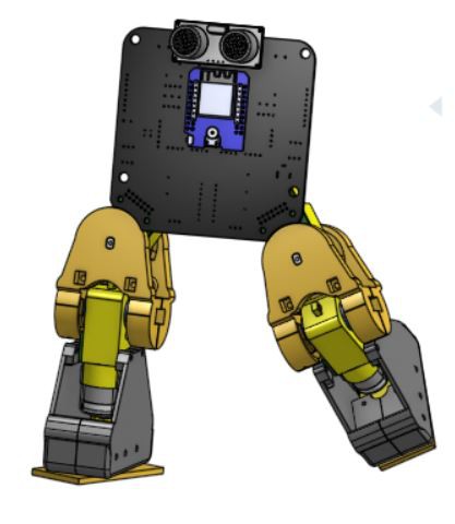
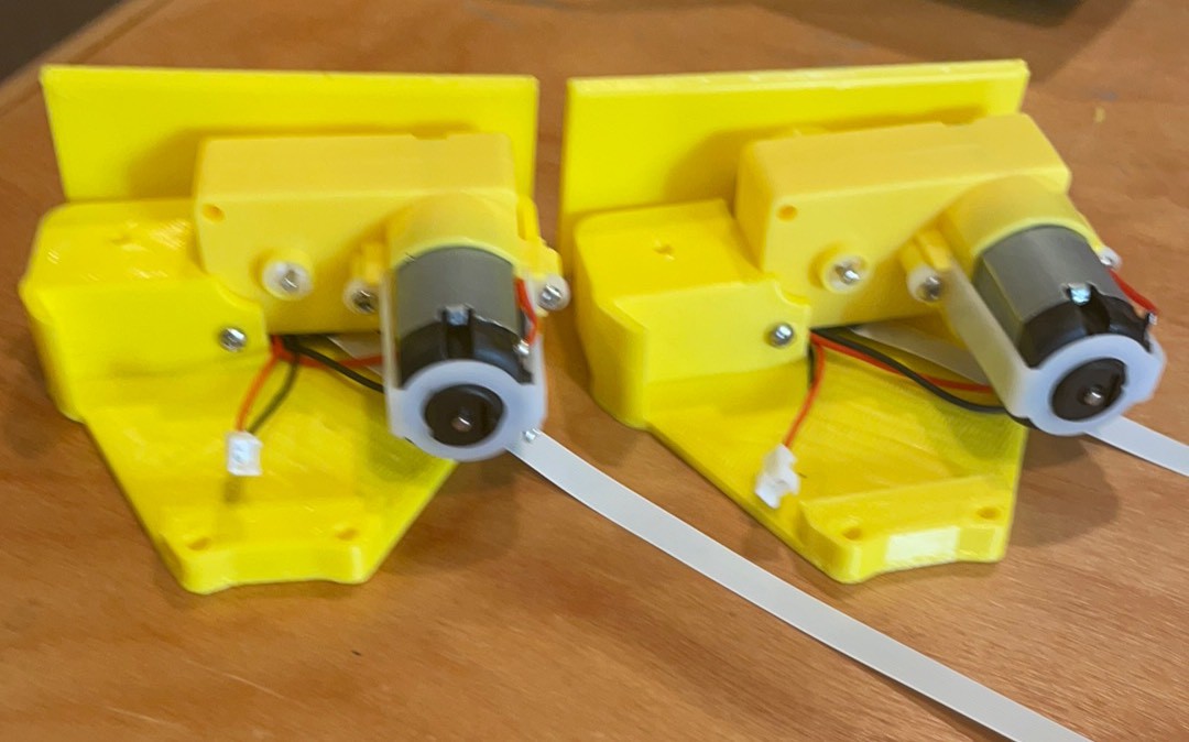
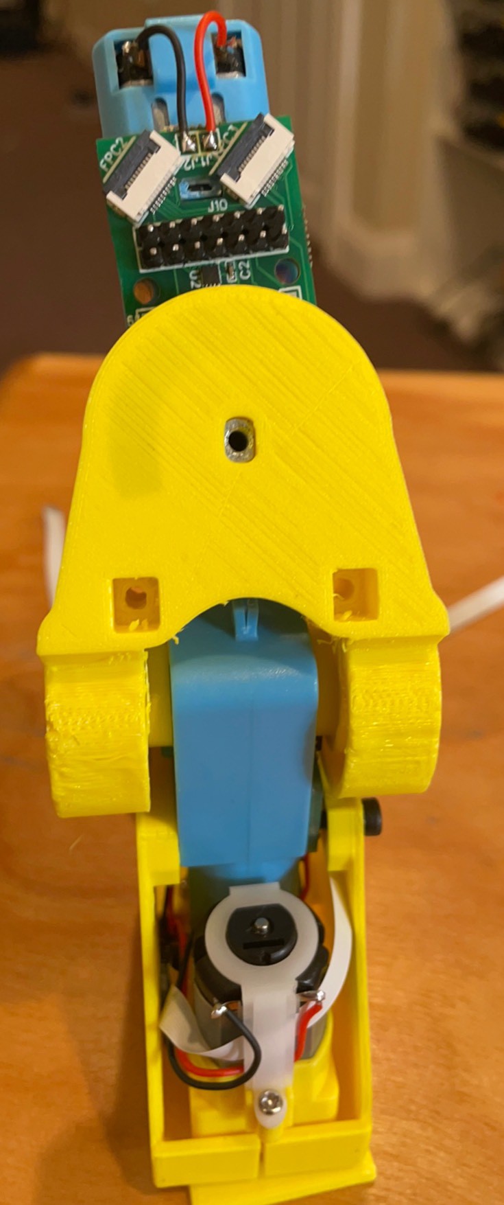
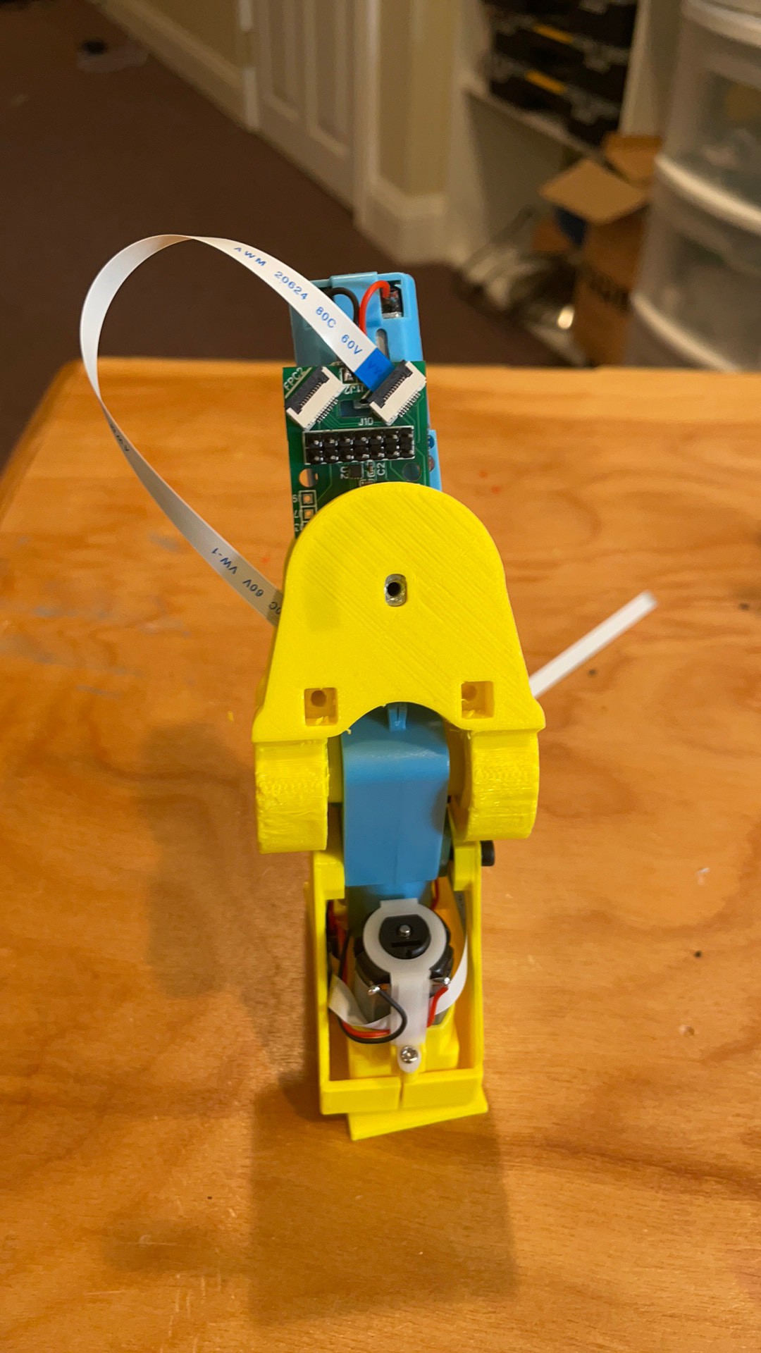
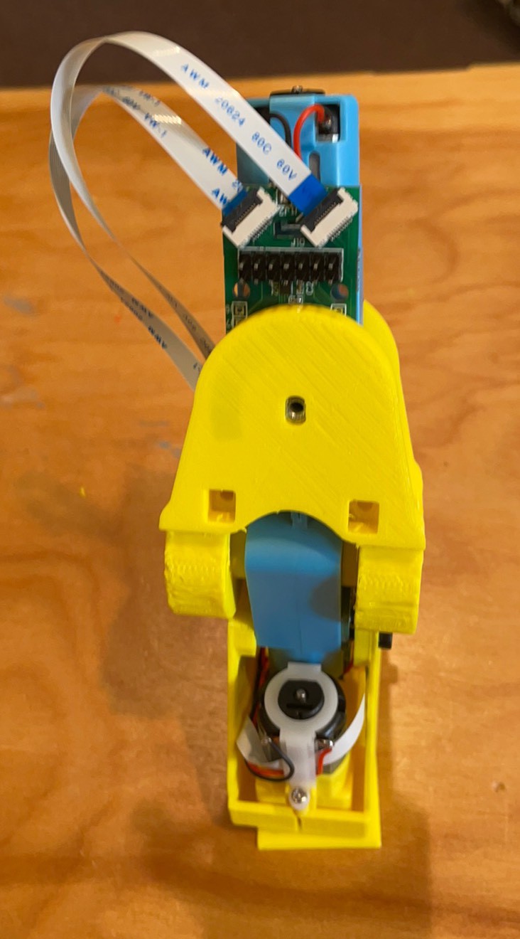
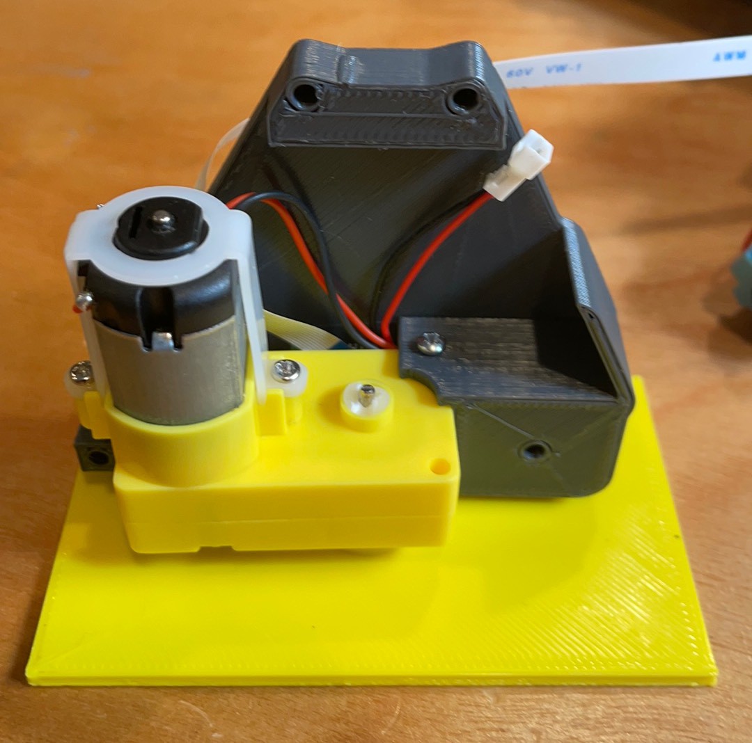
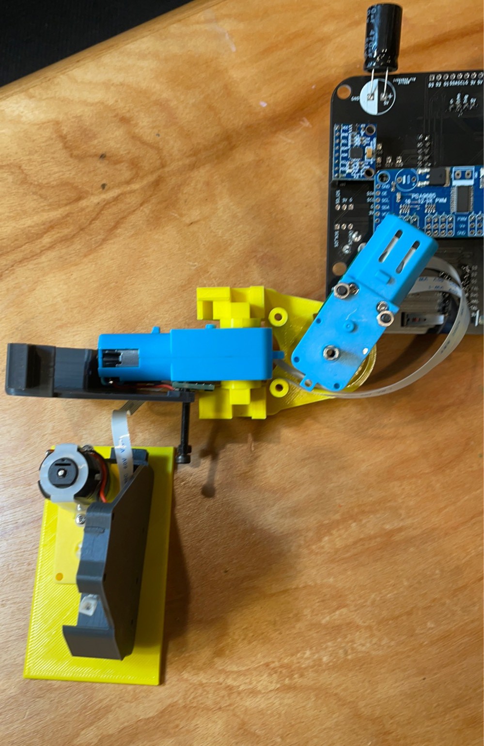
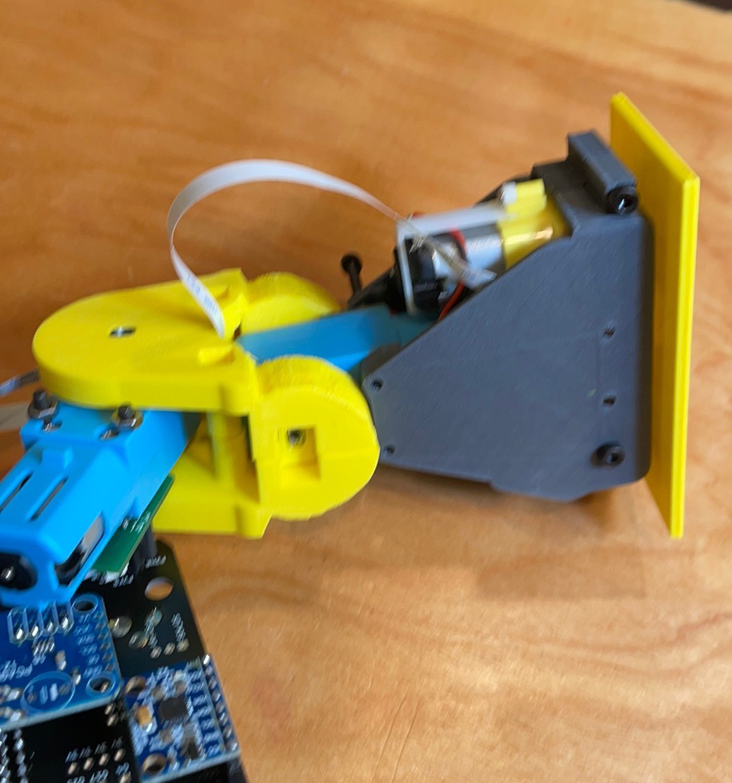
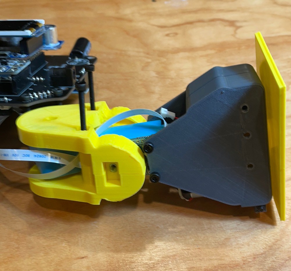
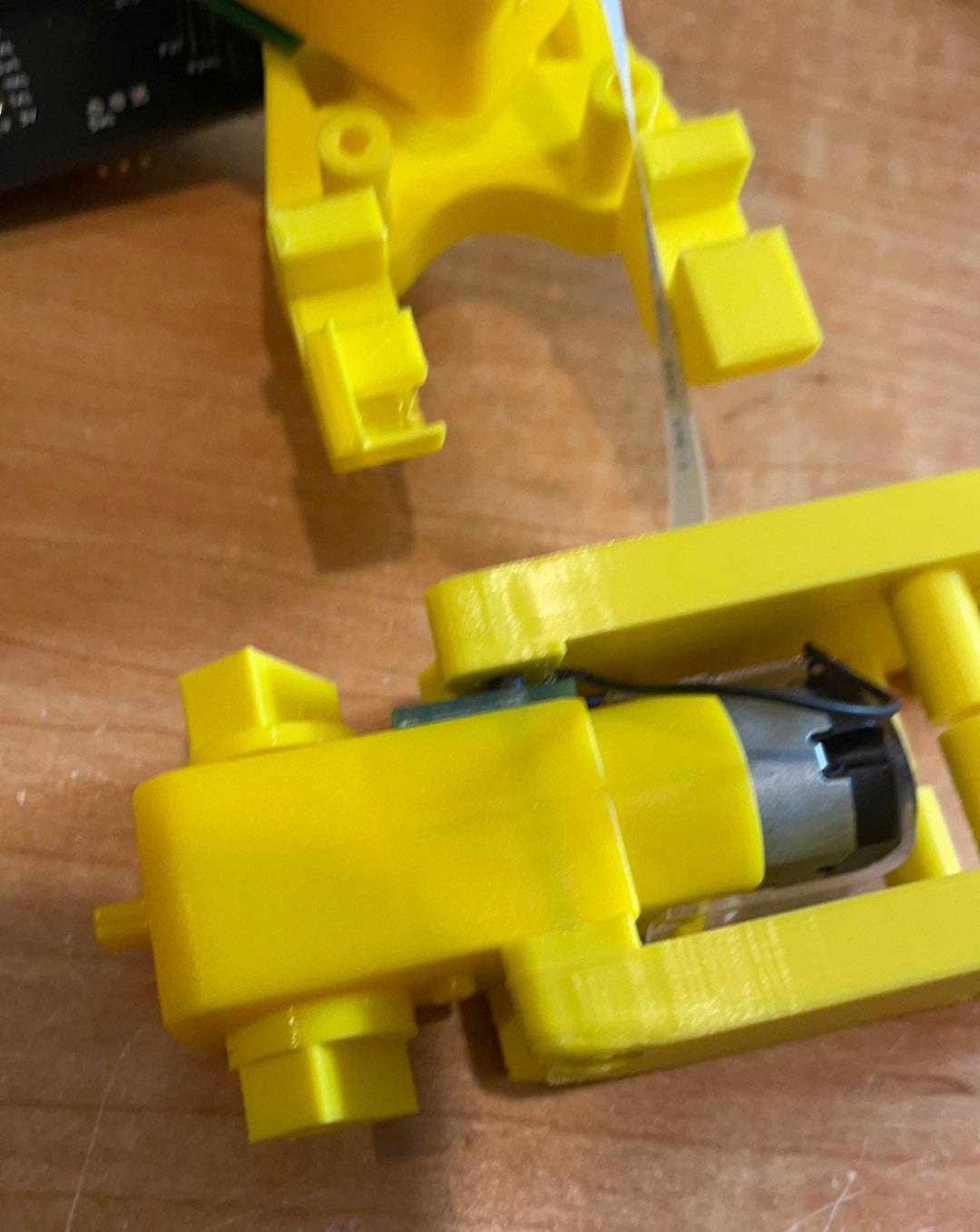
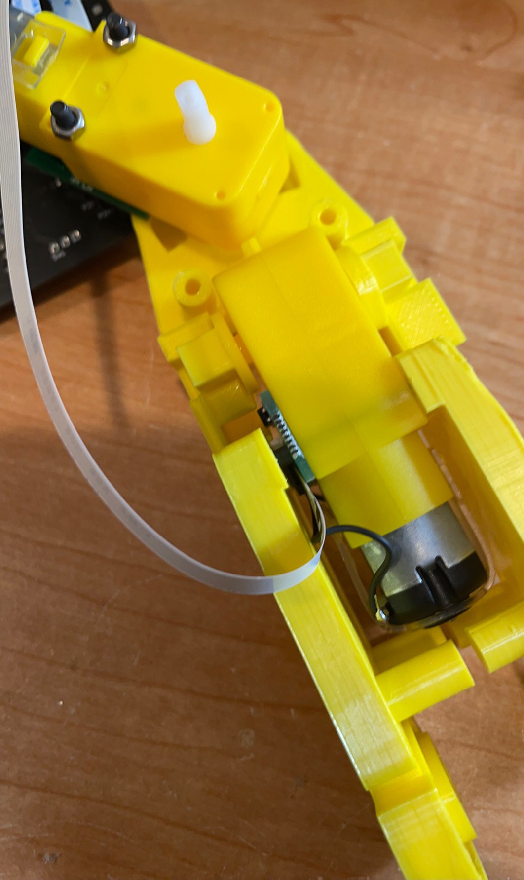
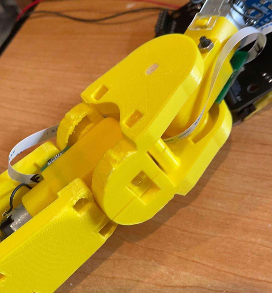
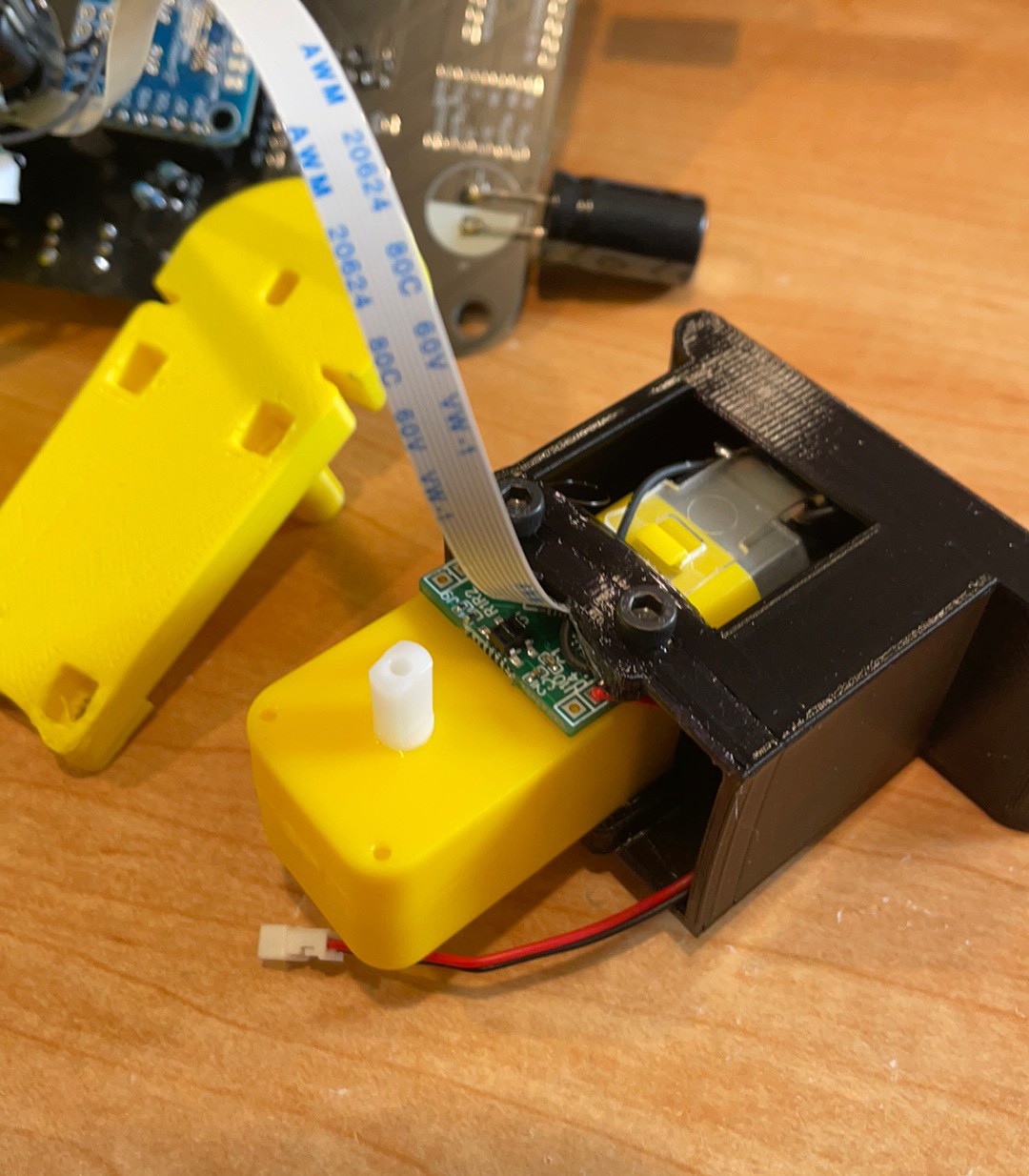
Twisty Shorty Assembly Continued
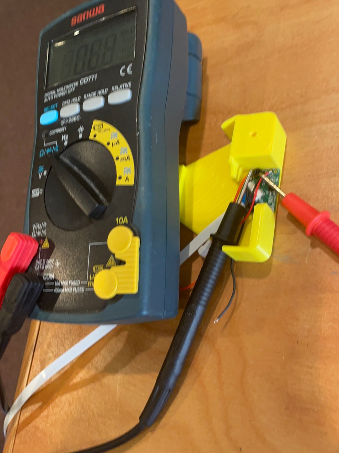
11/20/2021 at 12:46 • 0 commentsSo, after the previous assembly, I found some short comings.
Femur motor was not centered.
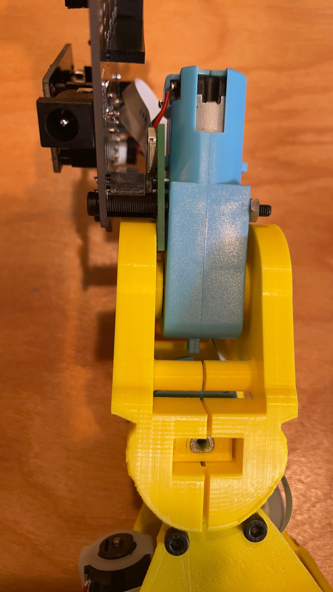
Tibia motor was not sufficiently captured.
Feet were not wide enough to balance well.
Batteries were not held in well.
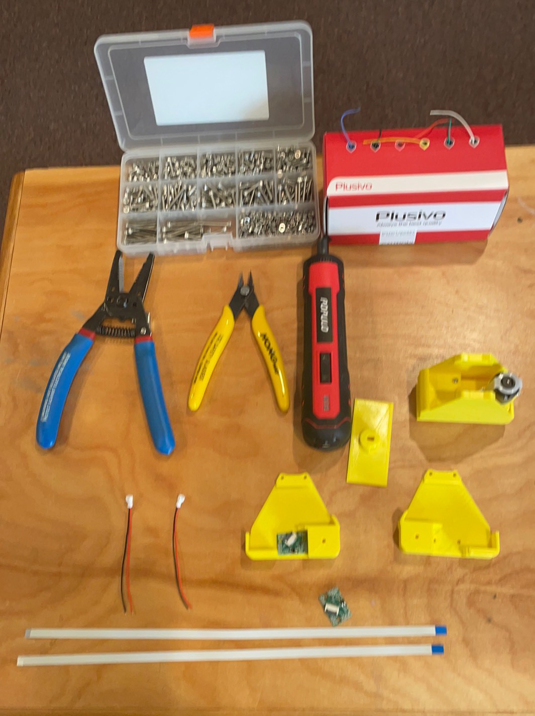
So after an hour of cad and a few hours of printing I am starting my assembly again.
Here are the pics of the process.
-
Building a Twisting Shorty Cya
11/13/2021 at 11:55 • 0 commentsI had designed the original legs for Cya to mimic the joints needed for a quadruped. It needs the 4 legs to be able to turn. They also were a little too tall which made it a little more difficult to balance. So to allow Cya to turn on a dime and show off the unique advantages of continue rotation servos, I designed a rotational stage on the soles of the feet. The Onshape model can be found here.
![]()
The foot can stay flat on the ground and if one leg is lifted, Cya can pirouette. Continuously. Like a roundhouse kick. Next goal, build it up and get a video of the pirouette. After than my next adventure will be working in Micropython.
Here are some assembly pictures for posterity.
Ready
Bat positive
Battery negative
Cut off top shaft.
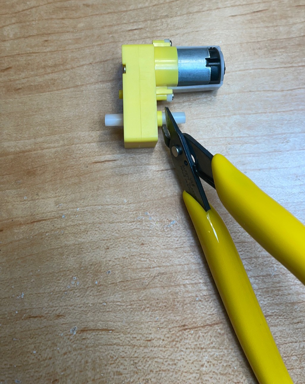
Cut complete
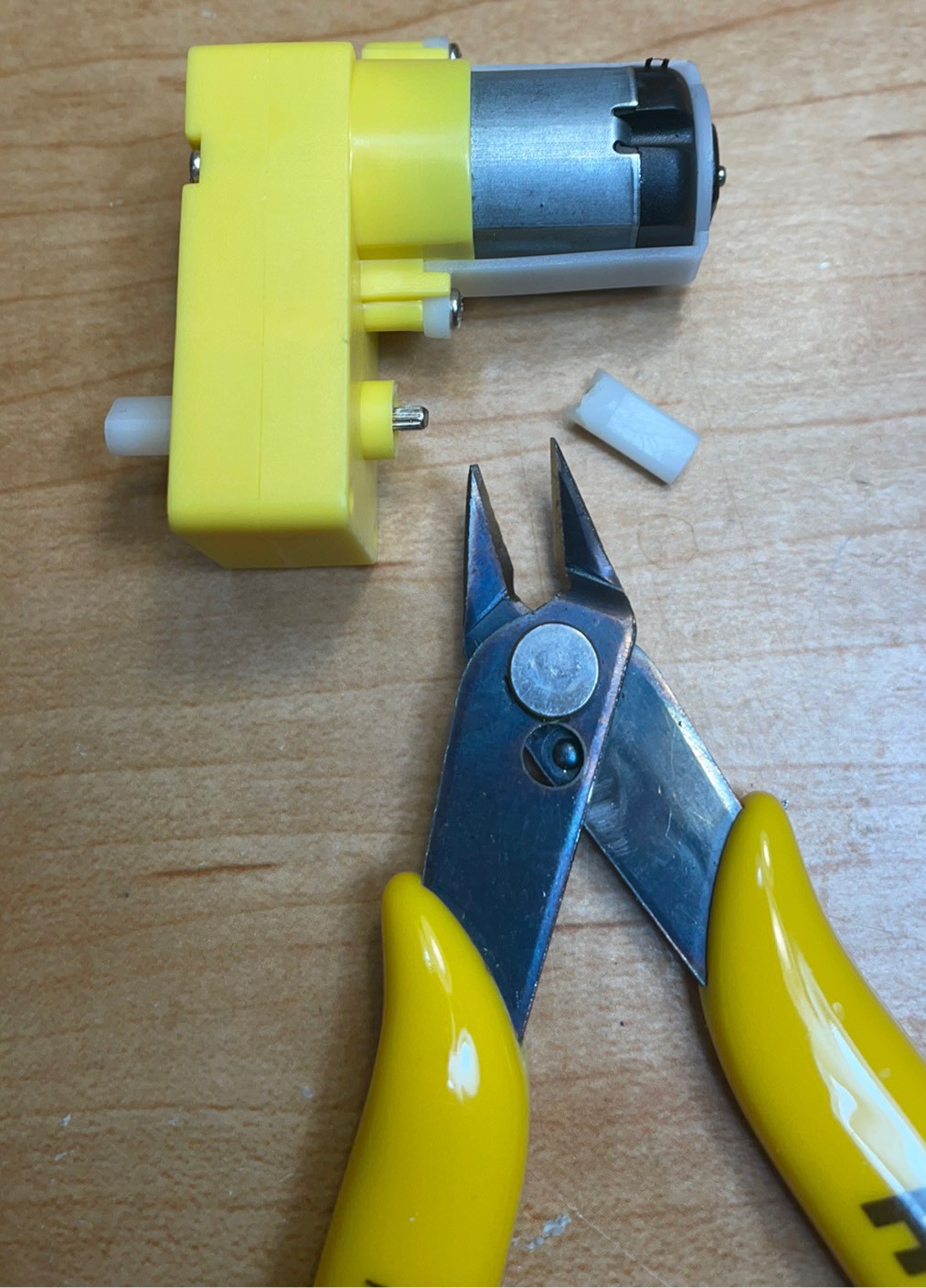
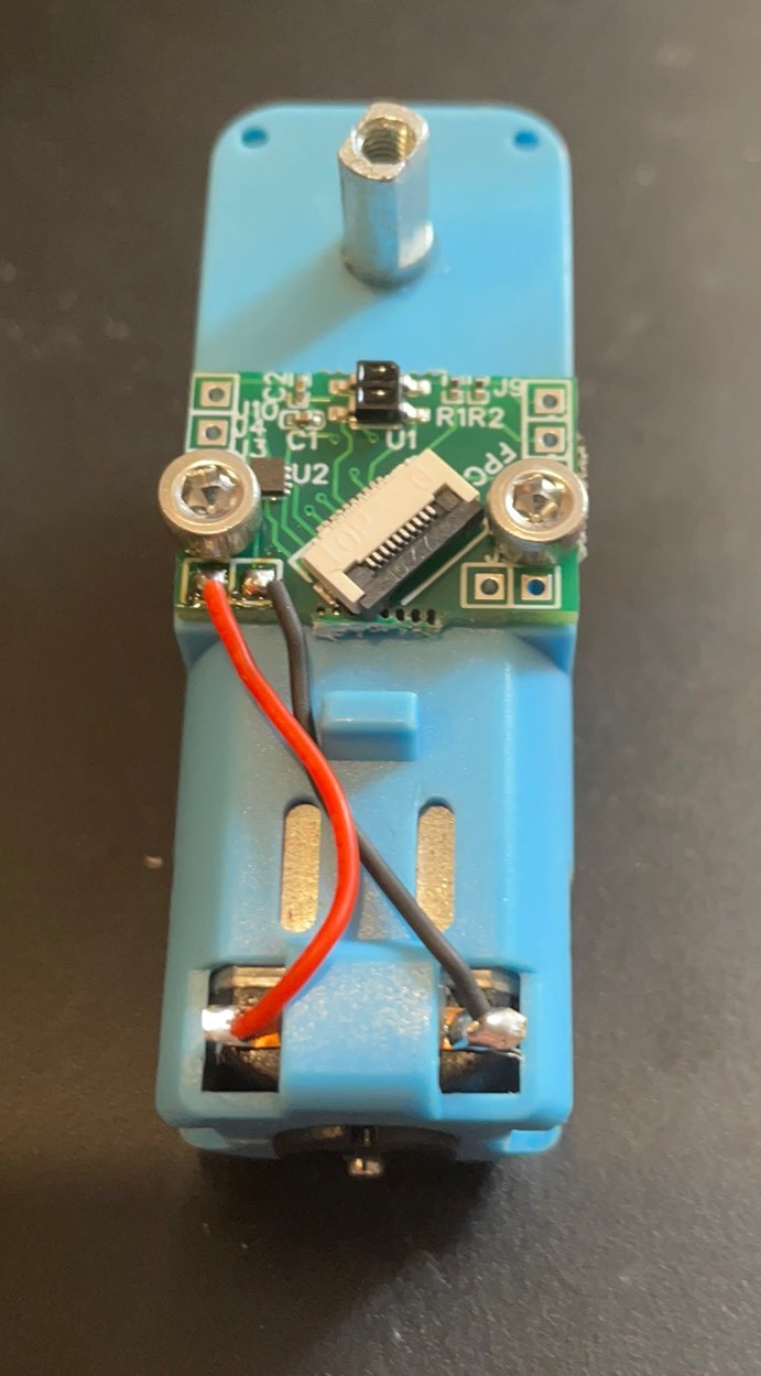
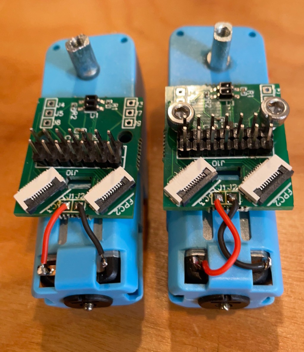
Solder on motor wires from the top to keep the back flat.
Front of boards done. Turn boards over to remove the excess solder to allow it to sit flat.
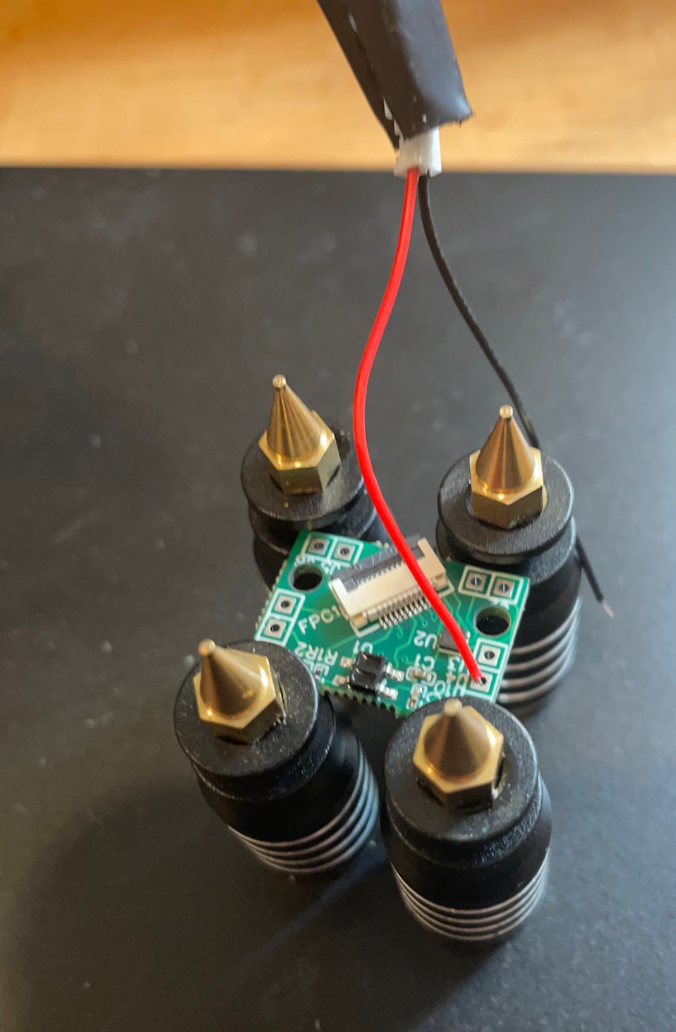
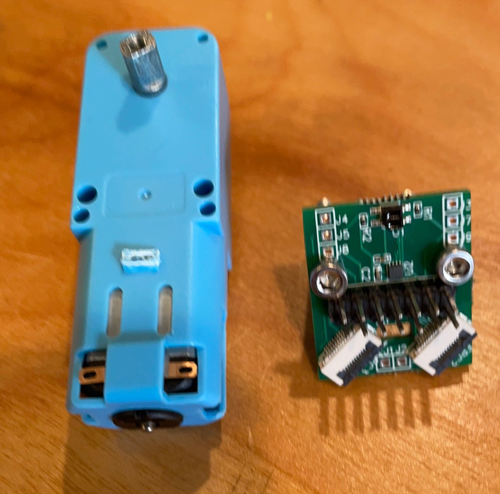
Insert cables blue side up, terminals down. Trying 25 cm. 20 cm works but is a little tight.
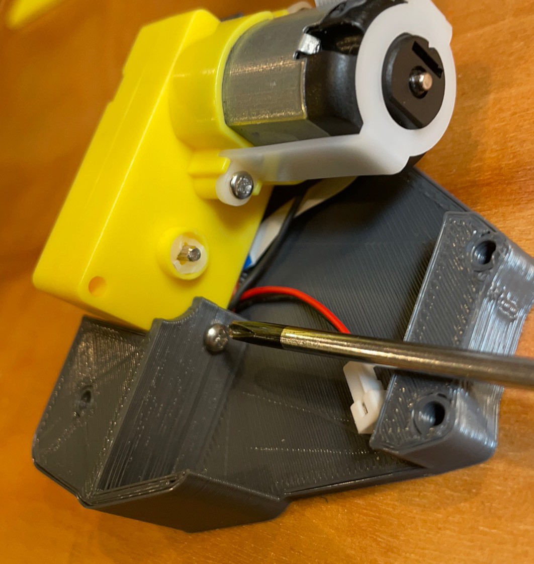
3x4mm flat head screws into the housing.
Check to make sure screw does not short To bat neg or motor positive or worse both! Use a washer if it does and a longer screw.
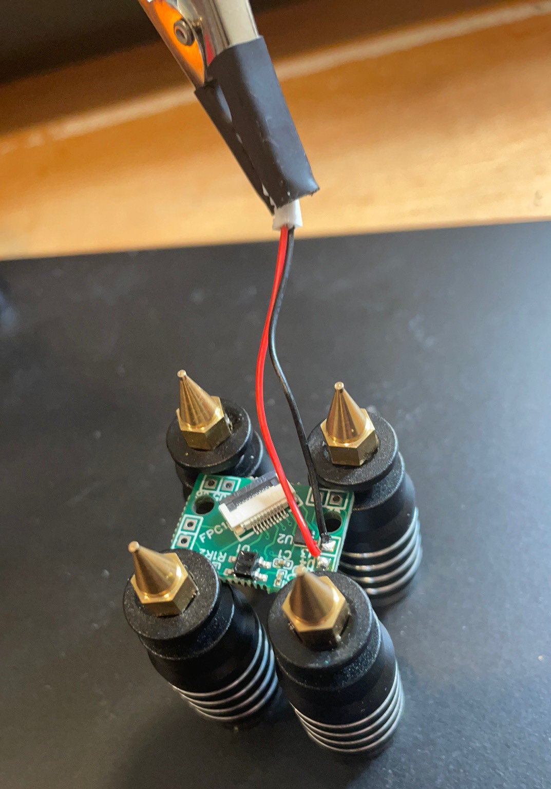
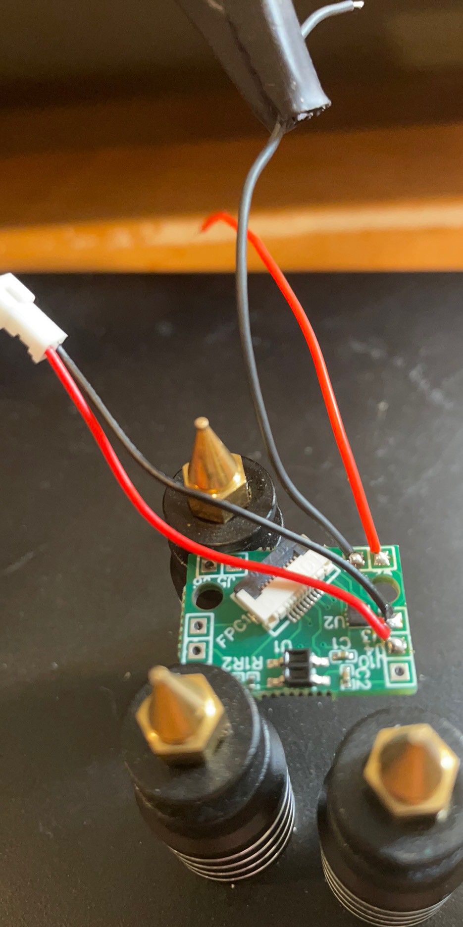
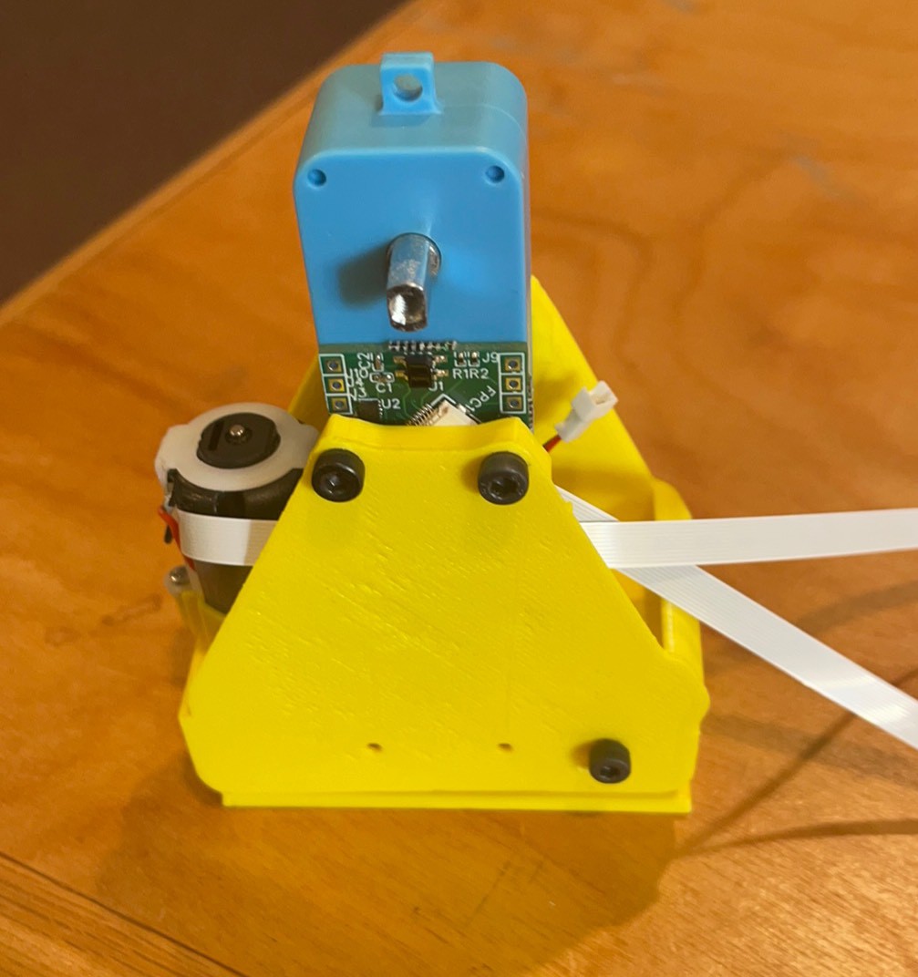
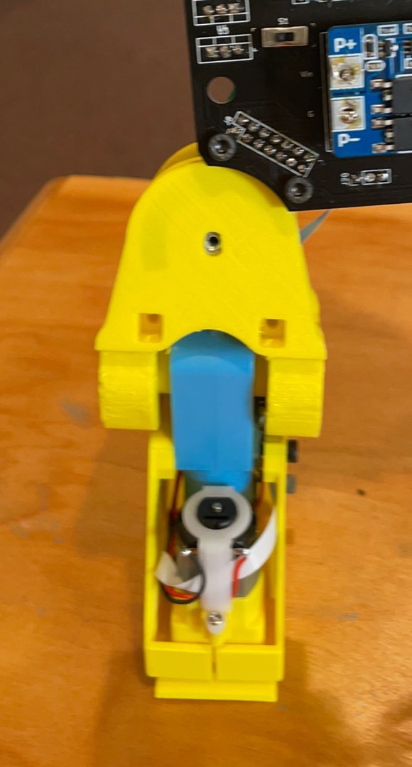
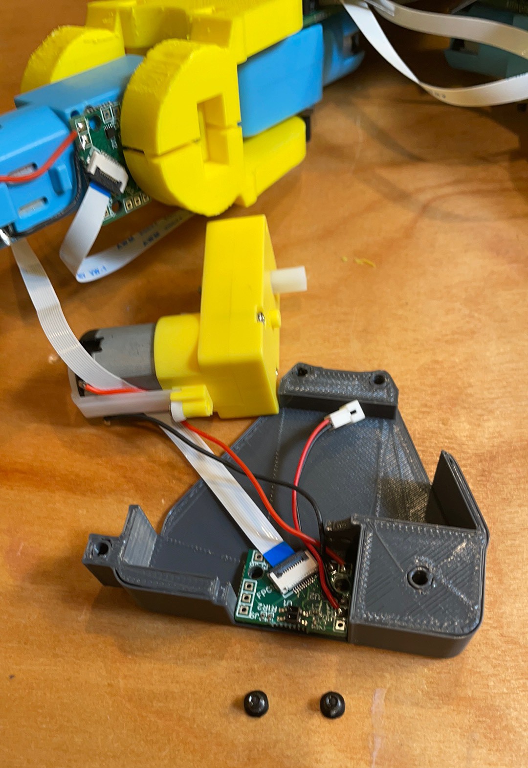
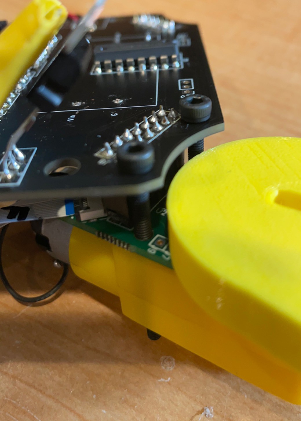
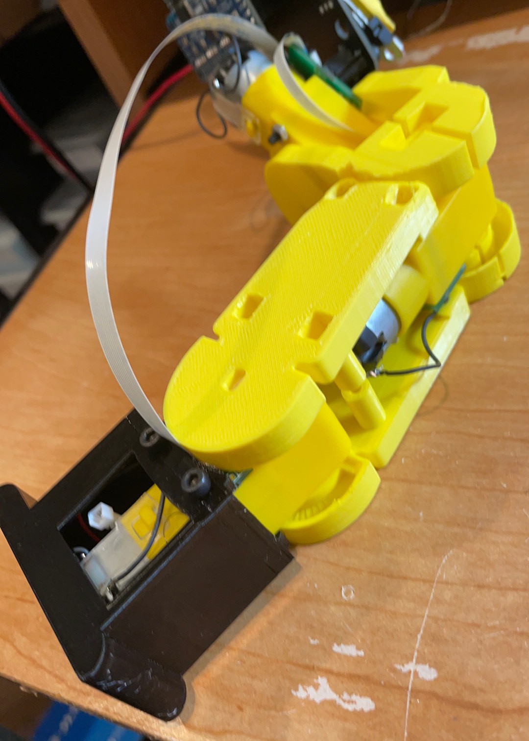
Route wires beside the FFC connector. It is line to line with the foot housing so wires above it will be squished.
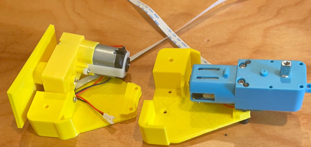
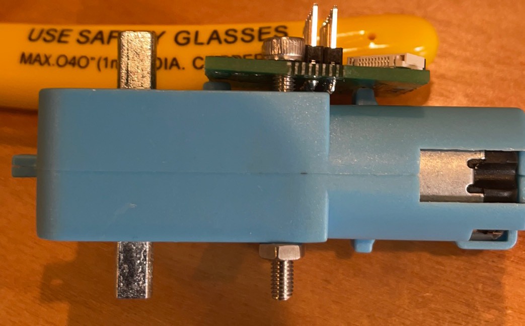
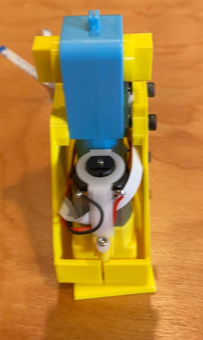
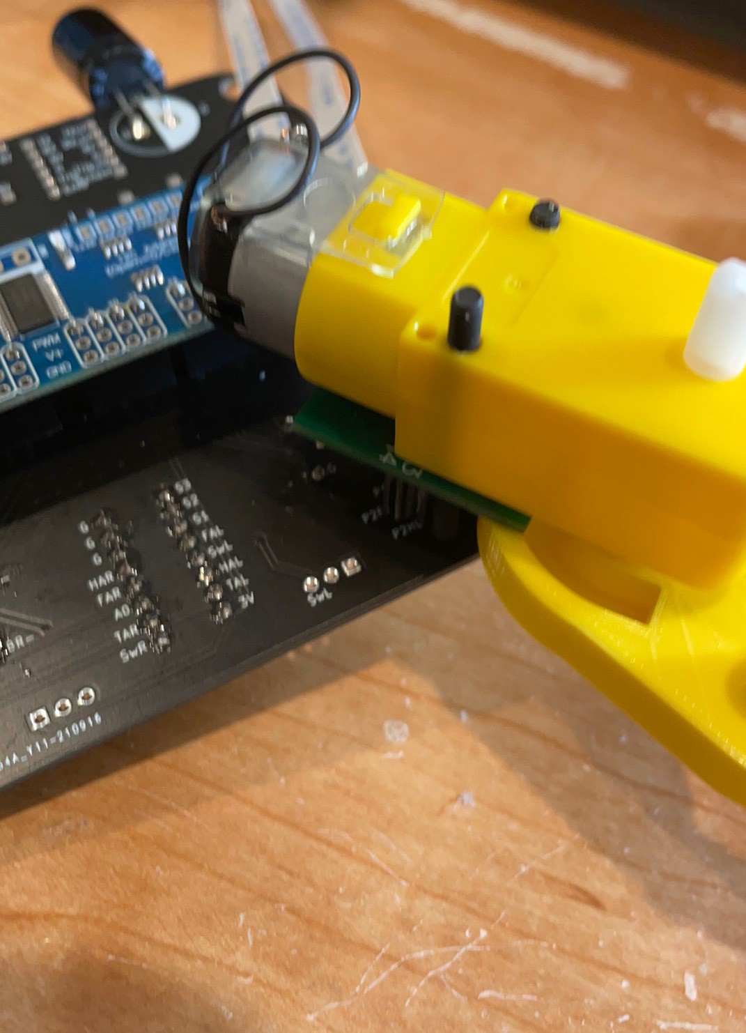
With and without the foot. Motor sits on the FFC connector and shaft boss is cradled buy the90 degree cut out.
Was designed for the shaft to be flush with the bottom but if they are even and the foot is secure it might be ok. If it is not pressed on enough the sensor will miss the reflector. Too tight and it will rub. This is a point for optimization. Fit is an elephant foot issue.
Put in the somewhat optional 2 mm screw in top of gearbox.
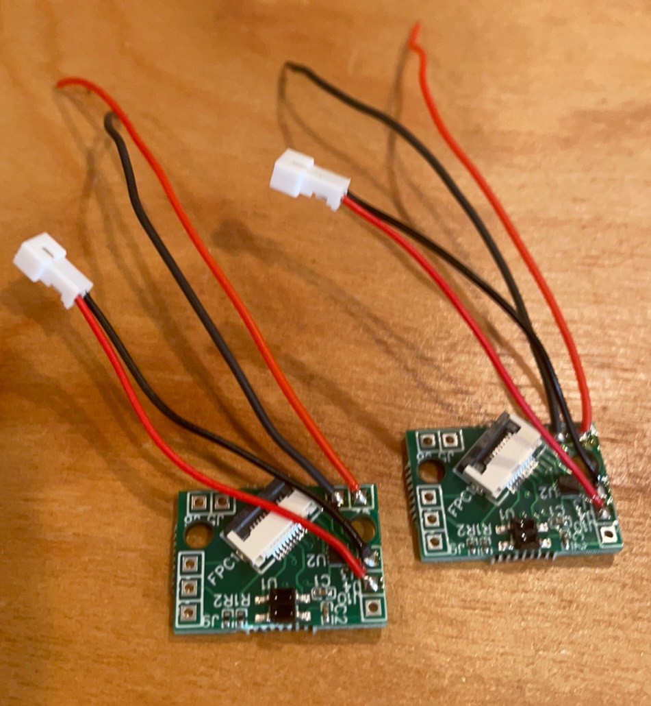
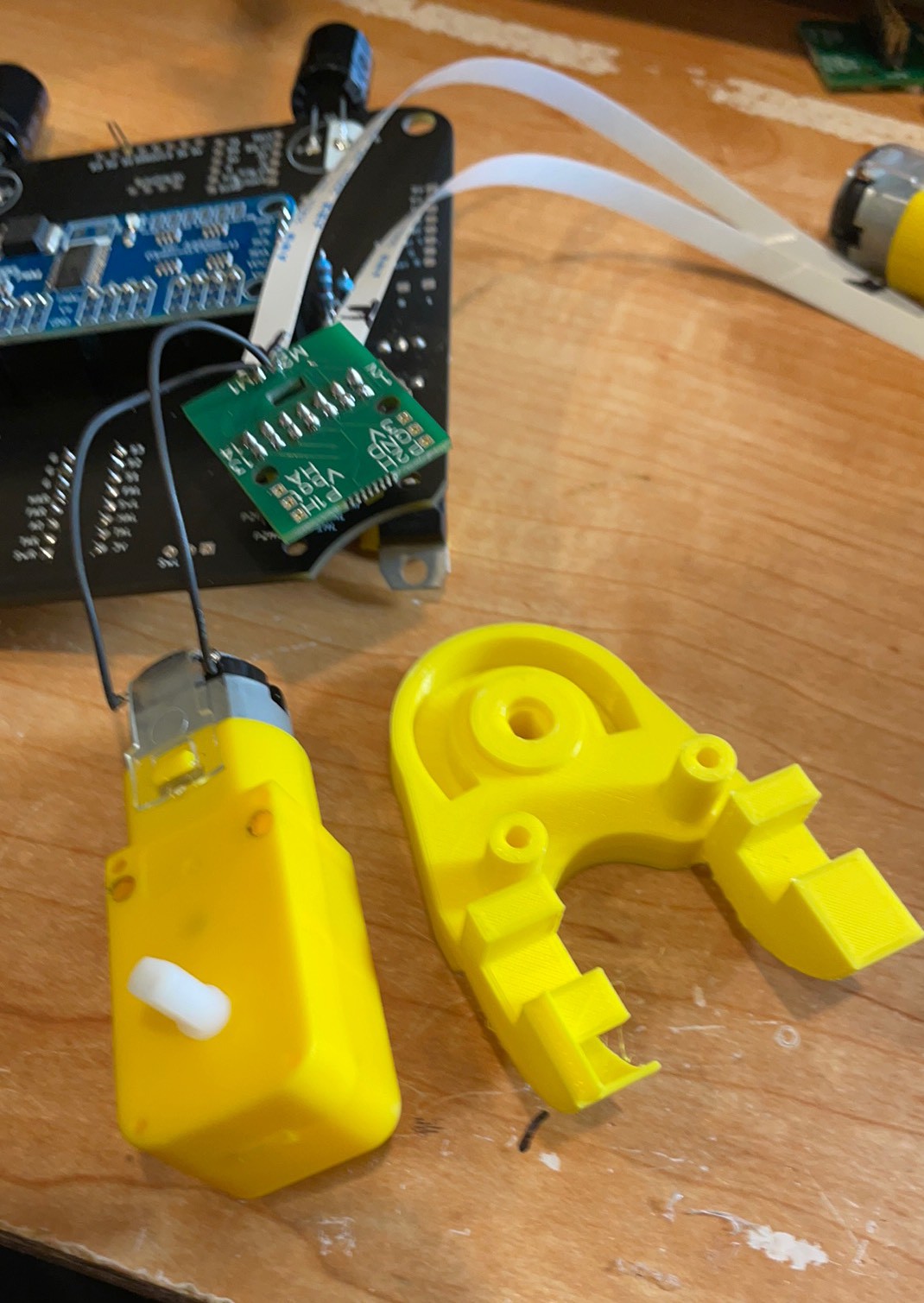
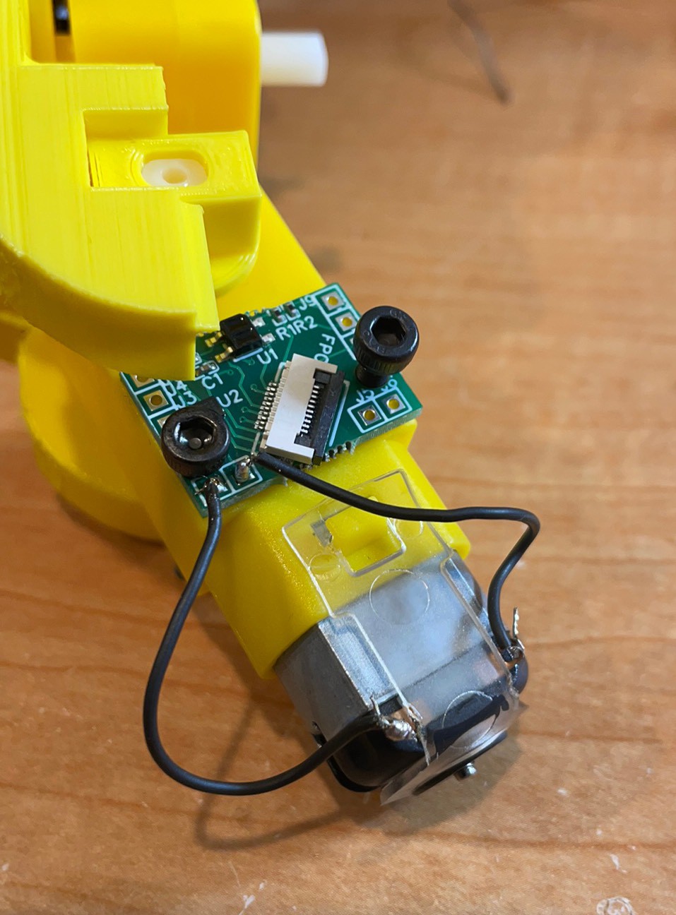
Black does the reaching here. Polarity is arbitrary until you try to use someone else’s code. Let’s standardize!
With 20 cm FFC and motor wires connected. Screws were just to hold it to solder.
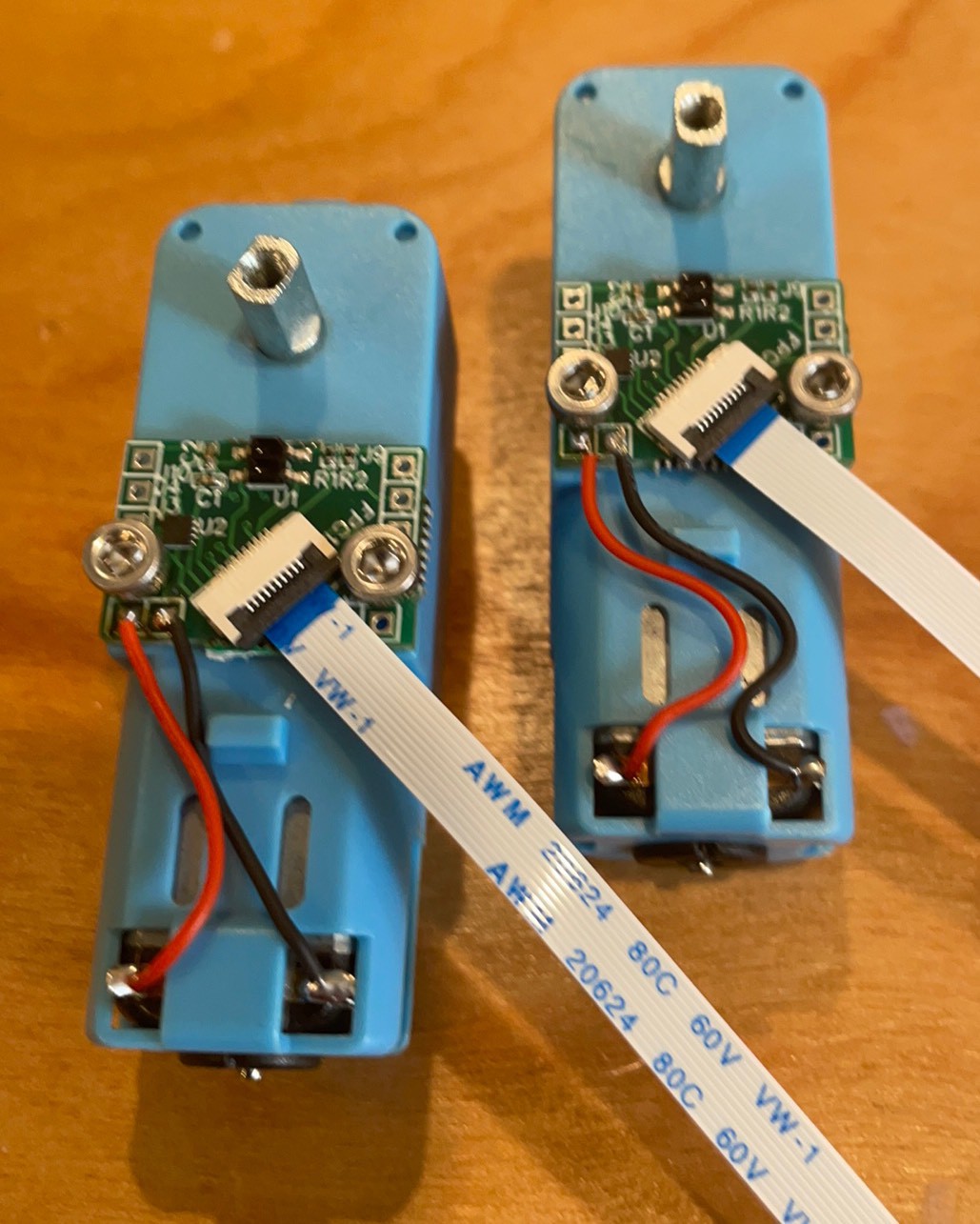
Assemble motor board and screws to other ankle.
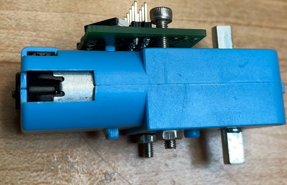
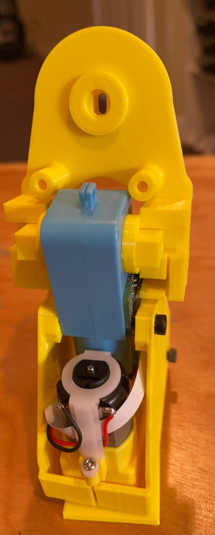
A finished foot.
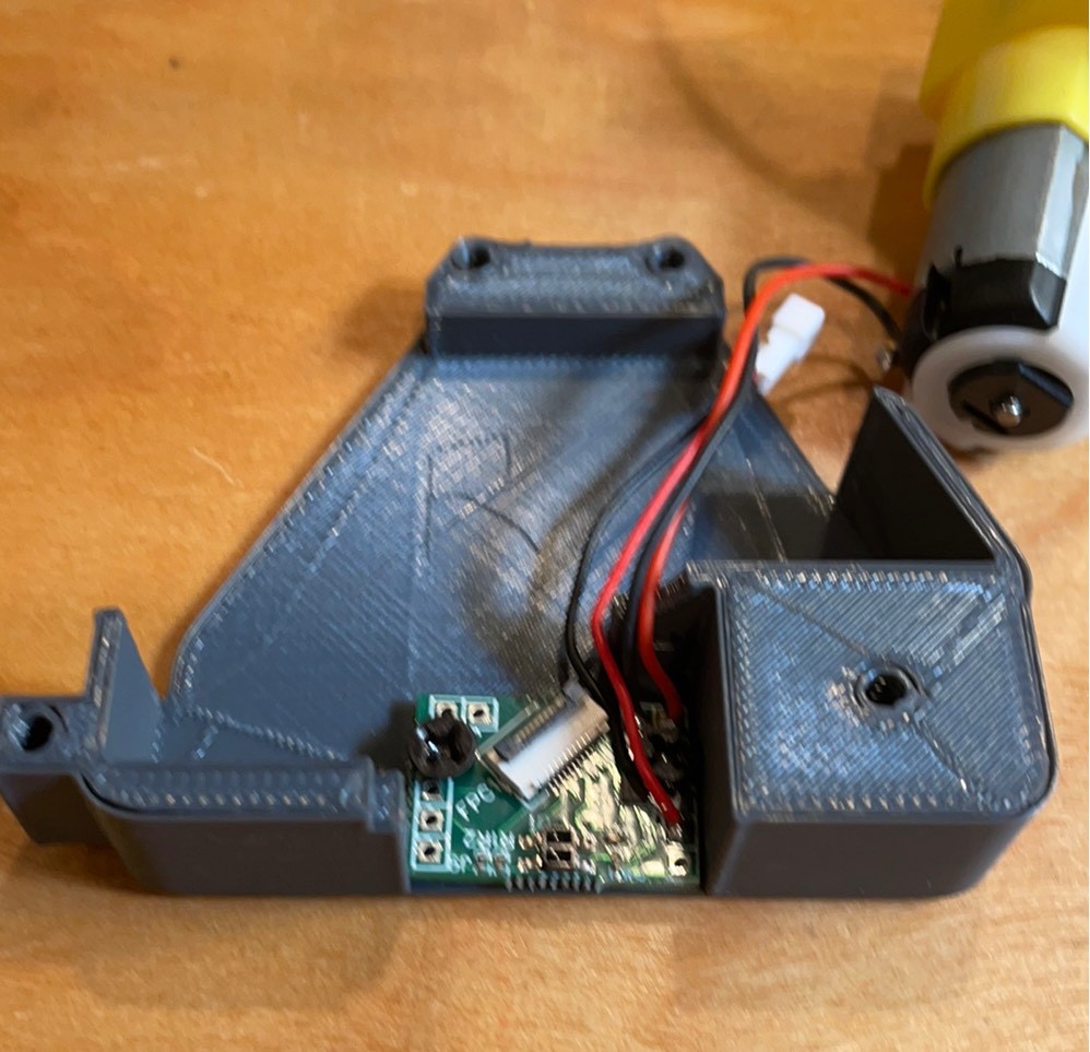
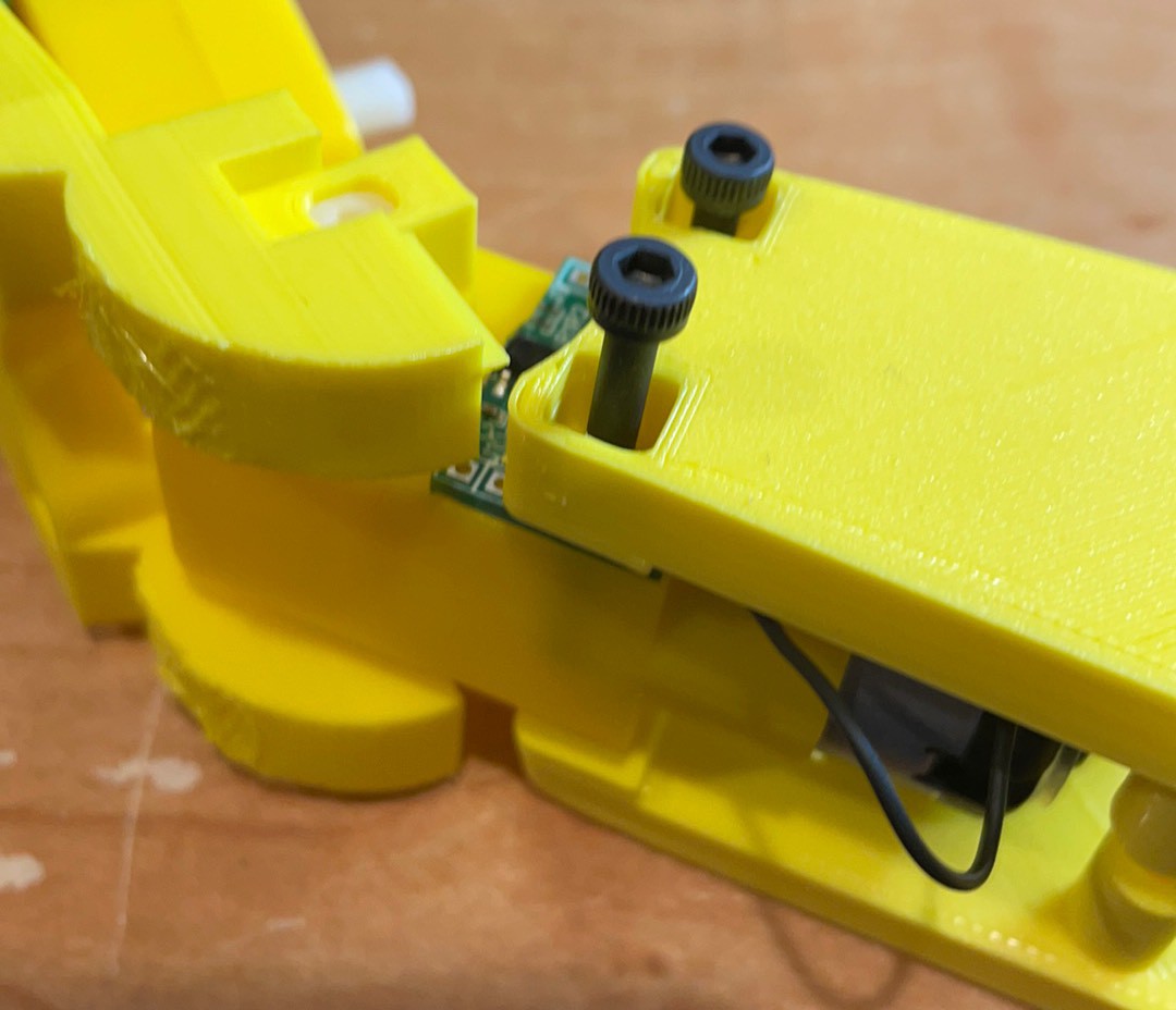
Gap at the back comes together with pressure. May need another screw boss. Not sure if the FFC against the motor will cause problems but it sure is tidy.
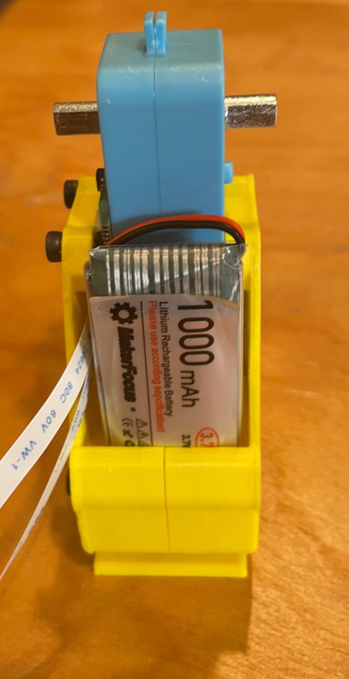
Need to pull the battery training wall up further. I guess it is zip ties for now.
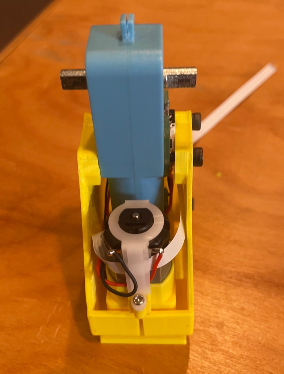
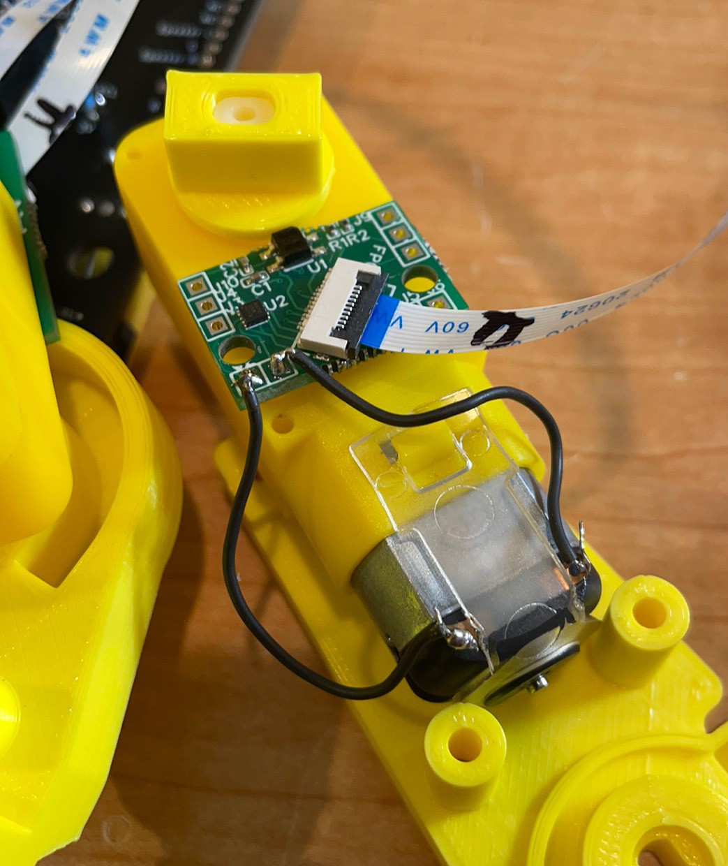
Finished. The rotation motor can slip out of its pocket. Needs a little better fixation but it functional. The 90 degrees around the shaft boss need to be opened up by 0.25 mm and a mother screw boss is needed.
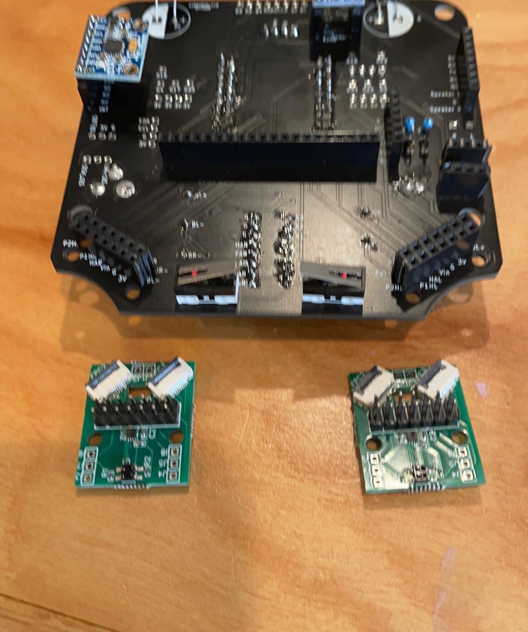
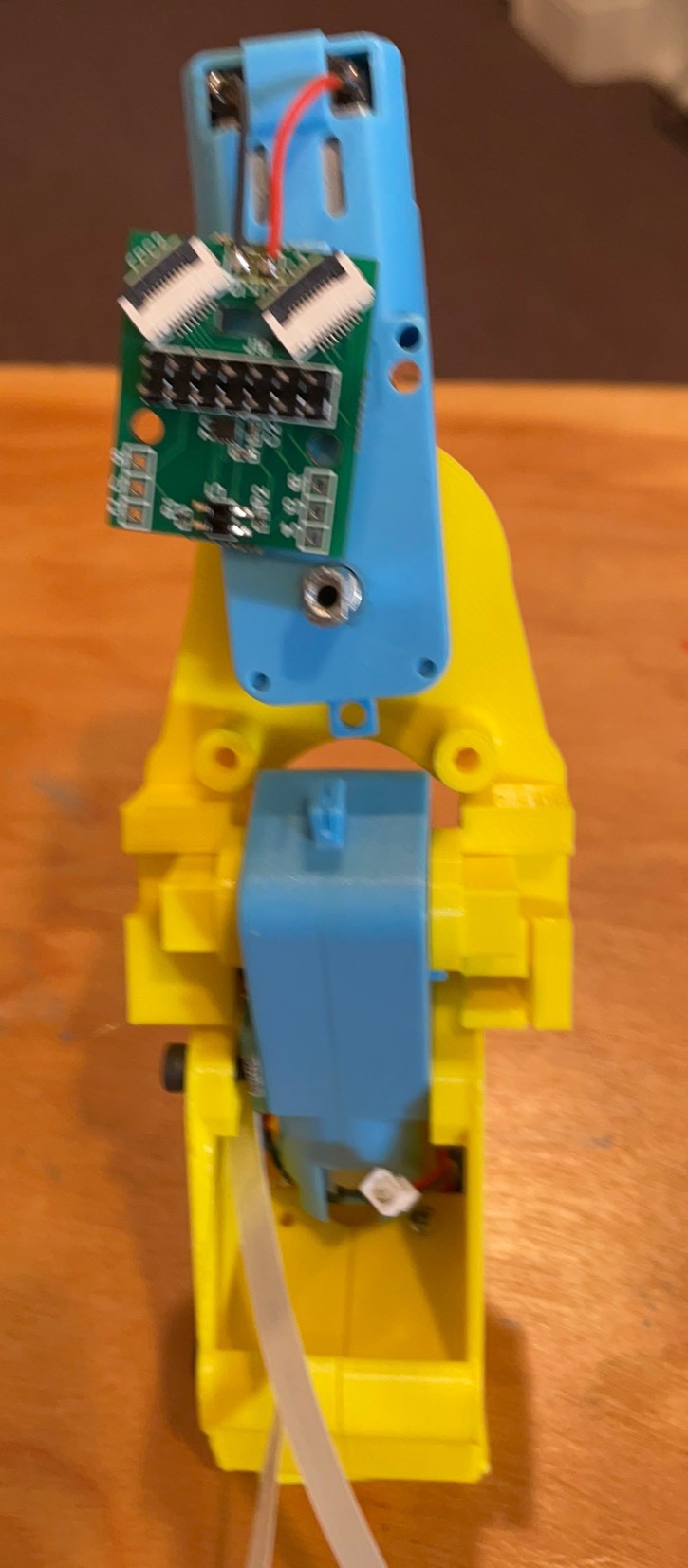
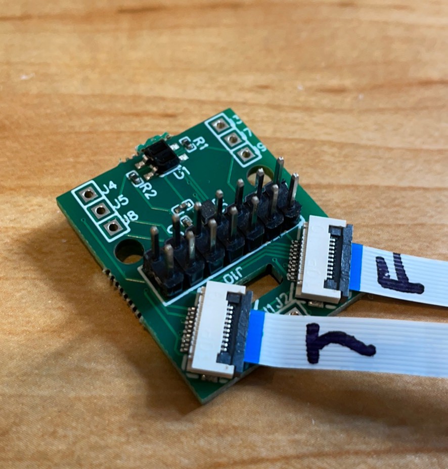
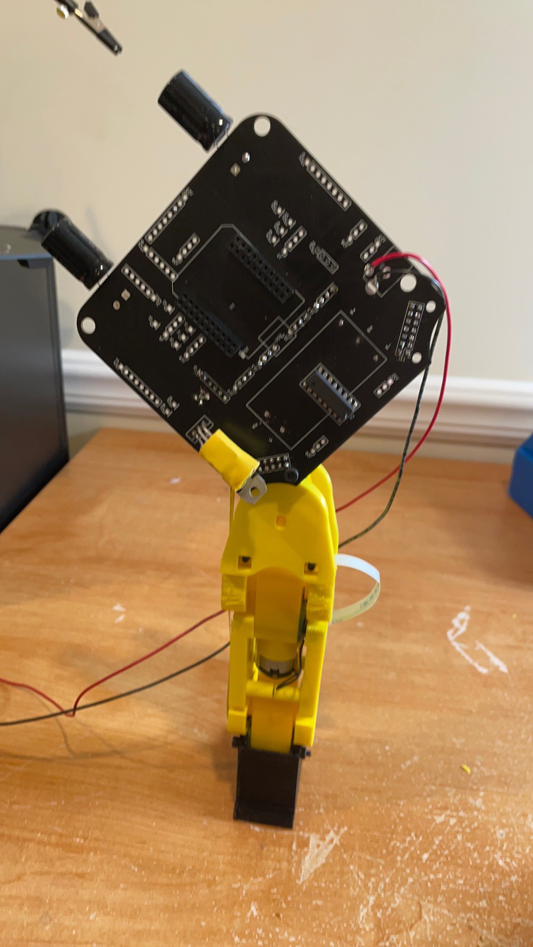
Female 2x7 headers on the back of the board and 2x7 male headers on the front of the hip boards. Be careful about the orientation because headers are hard to rework and if you can but it on backwards there is a better than even chance you will.
Three wrongs make a right? The pins need to move 2 mm down, and the rectangle window needs to be a 1mm bigger. Then if you cut way the boss it would sit flat. Now it is 2nm proud but I think it still works. Try to get it flat.
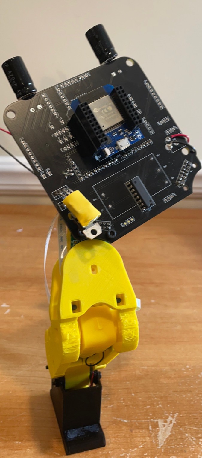
Moved it to the side with no boss and it is flat now. This keeps the motor terminals on the same side as the board which is a little cleaner.
Trimmed rectangle to height of header pins
Wires on.
Step 1 put on shaft adapters
Step 2 Hip on. Match the sensor with the slot.
Step 3 Board Forward!
Step 4 Add other hip.
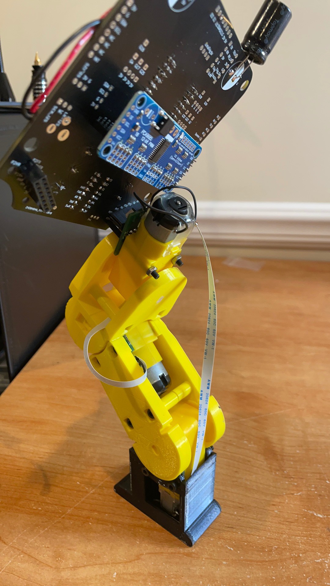
Route and attach the bottom tibia or rotation FFC.
Route and attach the femur or middle motor.
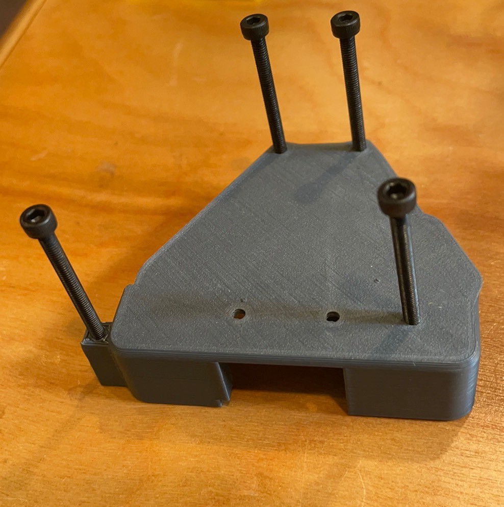
Plug one leg in and attach with 40mm m3 screws.
Which lead to backwards feet! I guess I need to turn them.
Tobi…

1 Add the Tibia board. Need to add labels to the 3D prints. Will scratch them in for now.
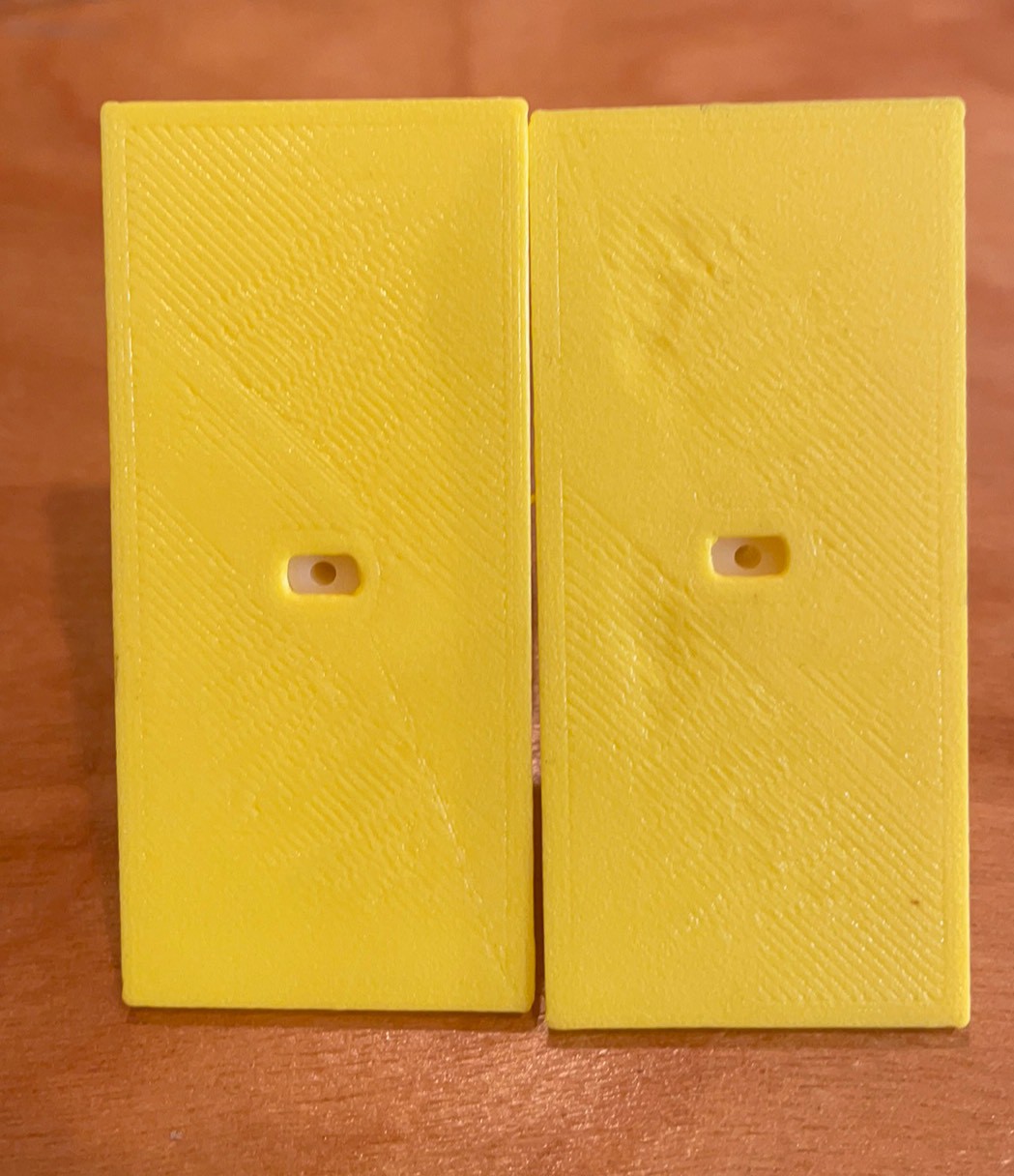
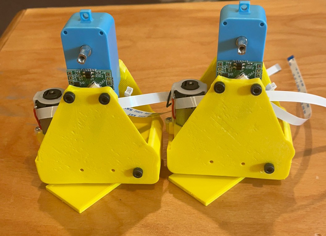
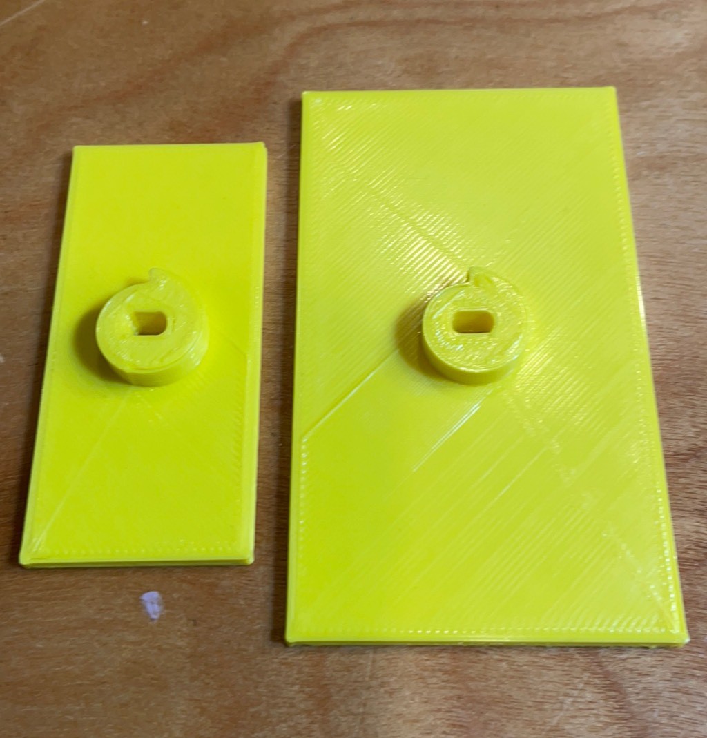
Old versus now feet. Let’s make this easy!
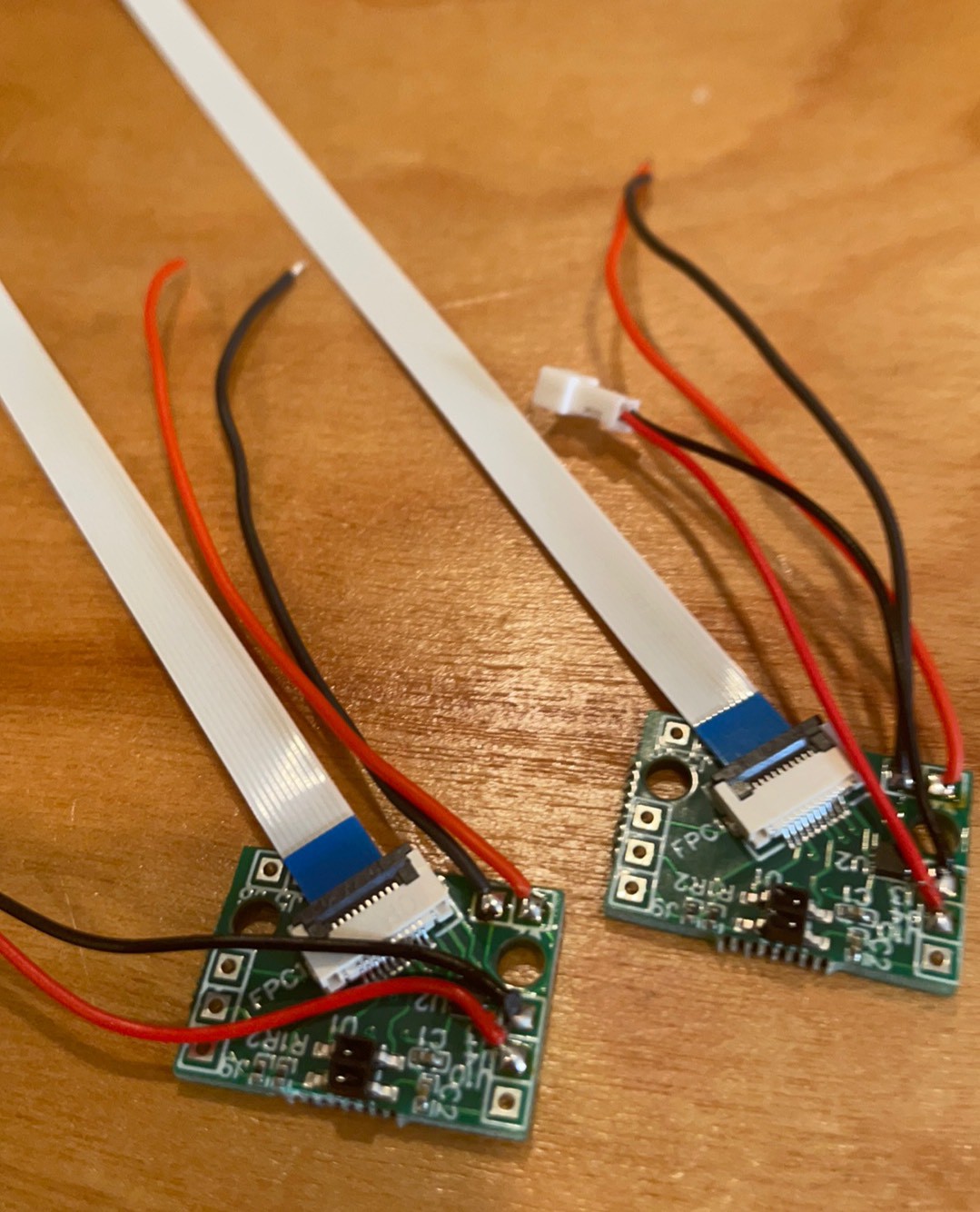
Attach FFC
Assemble and add 2 mm screw. I want to replace this screw but will keep it for now.
Board on femur motor facing the right way. To left when facing forward.
Add bottom screws first
Add screw at top of feet
One down. 9 screws all together. Preposition the screws when possible and save a half hour by using a cordless screwdriver.
Other foot.
Add 2 mm screw in top.
Pre-position screws on opposite side
Not quite how I planned it but it can not be changed without a reprint. Wanted the tibia motors in the back but I need to reverse the offset on the top of the ankles that makes room for the pcb to do that.

Trying again to flip the direction of the feet motors. 30 mm screws started.

Insert Tibia motor

Add 2 mm screw

Screws prostrated enough to pop into pcb holes. Deflect the plastic to do this.

Ended up putting in the screw from the pcb side because I could use the shorter 30 mm screw. Need 35 from the non pcb side.

Back to the design intent. Still can go a little higher on the batteries to hold them in better.

-
Super Mailbag
11/06/2021 at 10:17 • 3 commentsI received two big shipments for parts.
First my parts I ordered from Ali Express arrived. This is first time i have gotten parts since the pandemic started and shipping started to suck. Took about a month which is about where it was pre-pandemic so that is awesome. I got the following parts in:
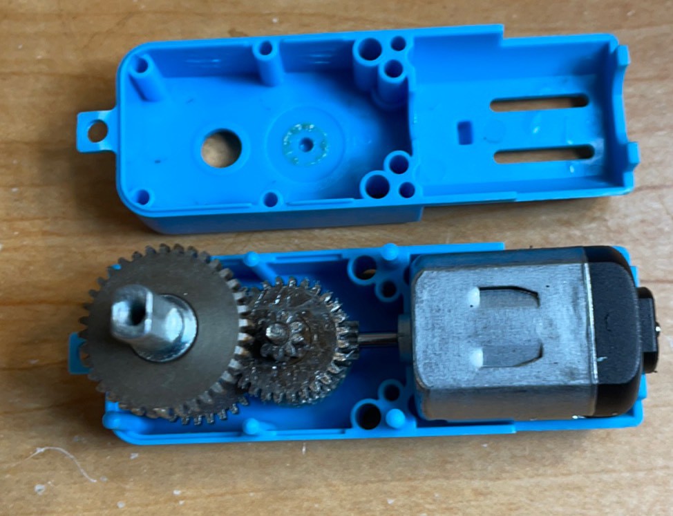
Blue metal gearbox motors. - I have been overpowering the 1:120 gearbox with the new 7-8V design. I am hoping the 1:90 metal gearbox motors stand up better.
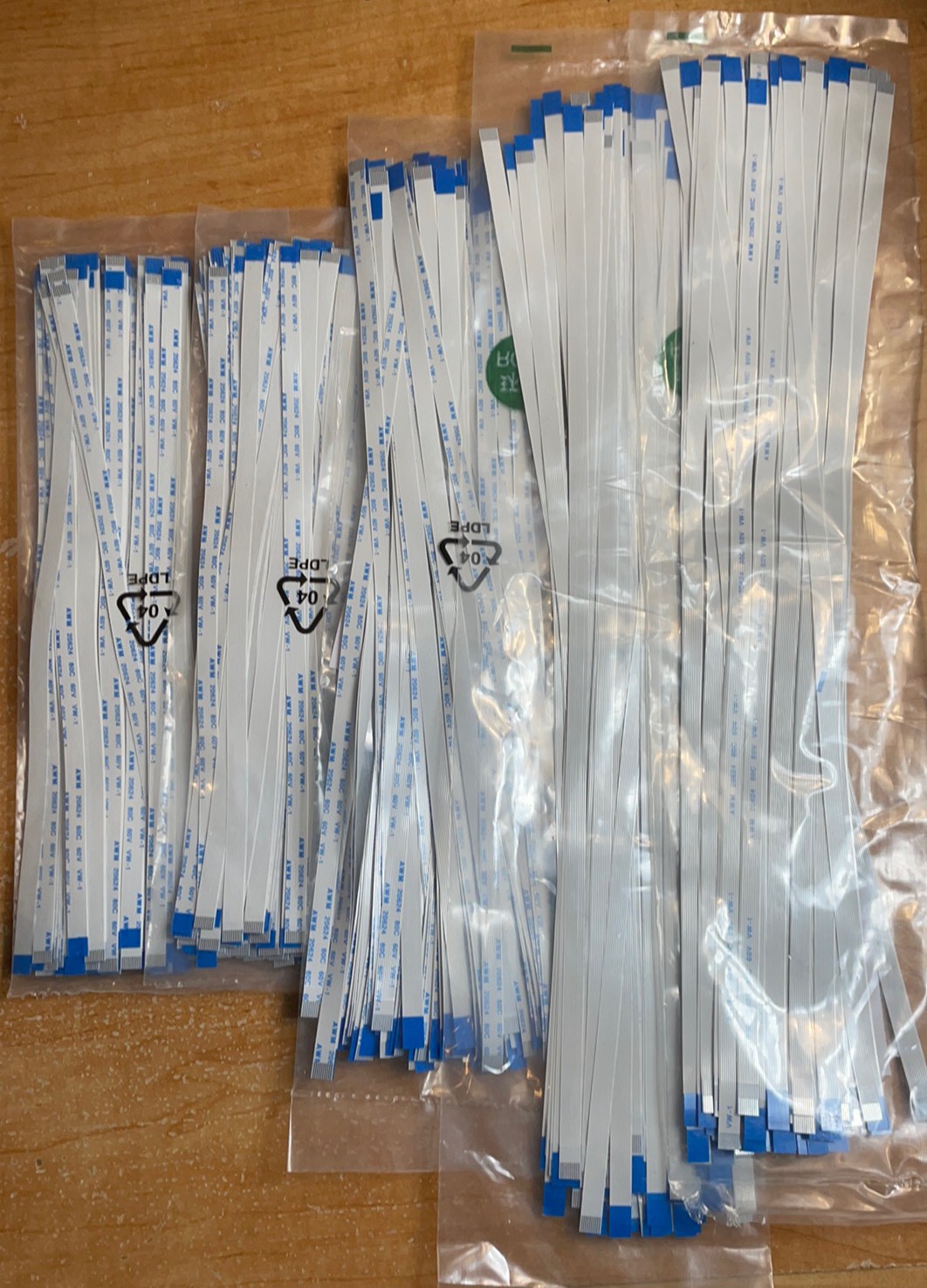
Longer FFC's - I could not get anything longer than 8 inches on Amazon. I got some 10 and 12 inch versions so I can go back and make the full sized version now.
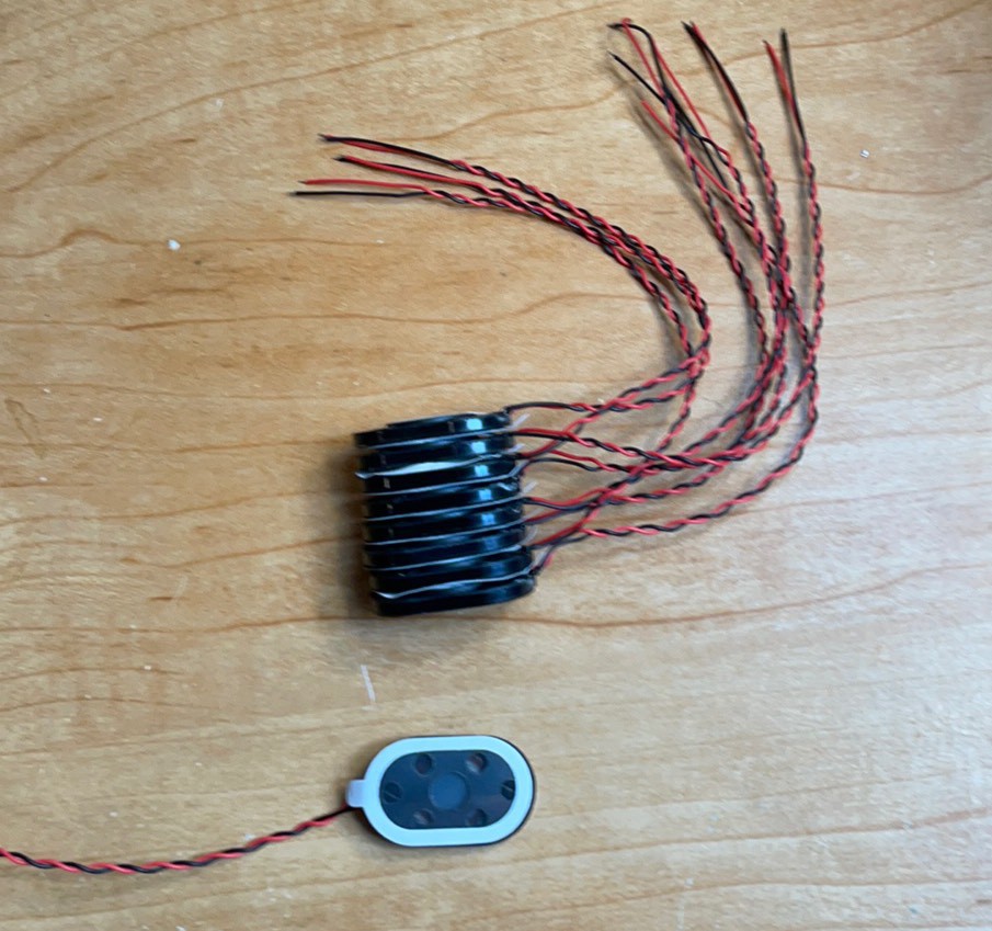
Tablet speakers - I got the speakers in the description with the adhesive front and back. I think this will easily double the sound. They are twice as big so that is logical right! Actually I think it has more to with controlling the front and back cavities on the speakers and having a adhesive mount will make that easier. I am looking forward to experimenting with these.
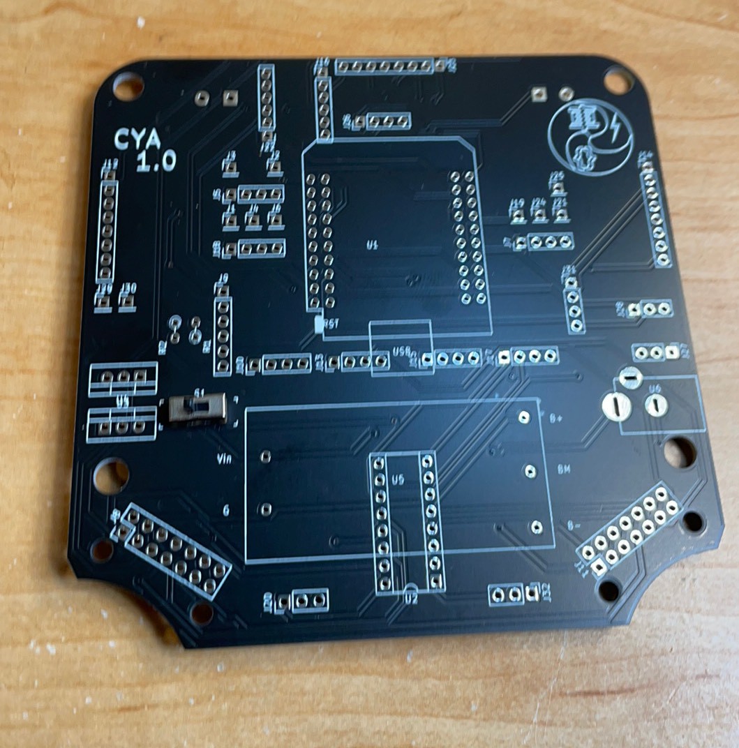
The second shipment was new PCB's. Cya 1.0. The improvements are:
1) Added a switch between the BMS and the rest of the circuit. Now you can charge without the robot being on. Also the BMS can come up to voltage before it starts powering the regulators. When I did not do this, the regulator when to 1V instead the 7-8 expected with two batteries in series.
2) Corrected polarity on the power jack.
3) New silk screen with the SCL and SDA positions corrected on the battery and the new version and logo.
Here's hoping that my power circuit is finally done and dusted.
I got twenty of them so if anyone is interested, leave a comment and we can connect so I can send you one.
Blue motor
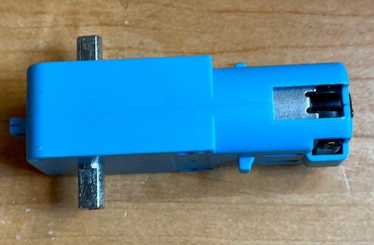
1:90 metal gearbox.
200, 250, and 300mm FFC’s.
Tablet speakers
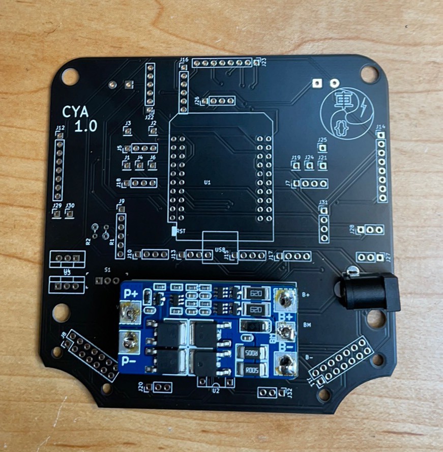
New PCB with switch
Power jack and BMS work.
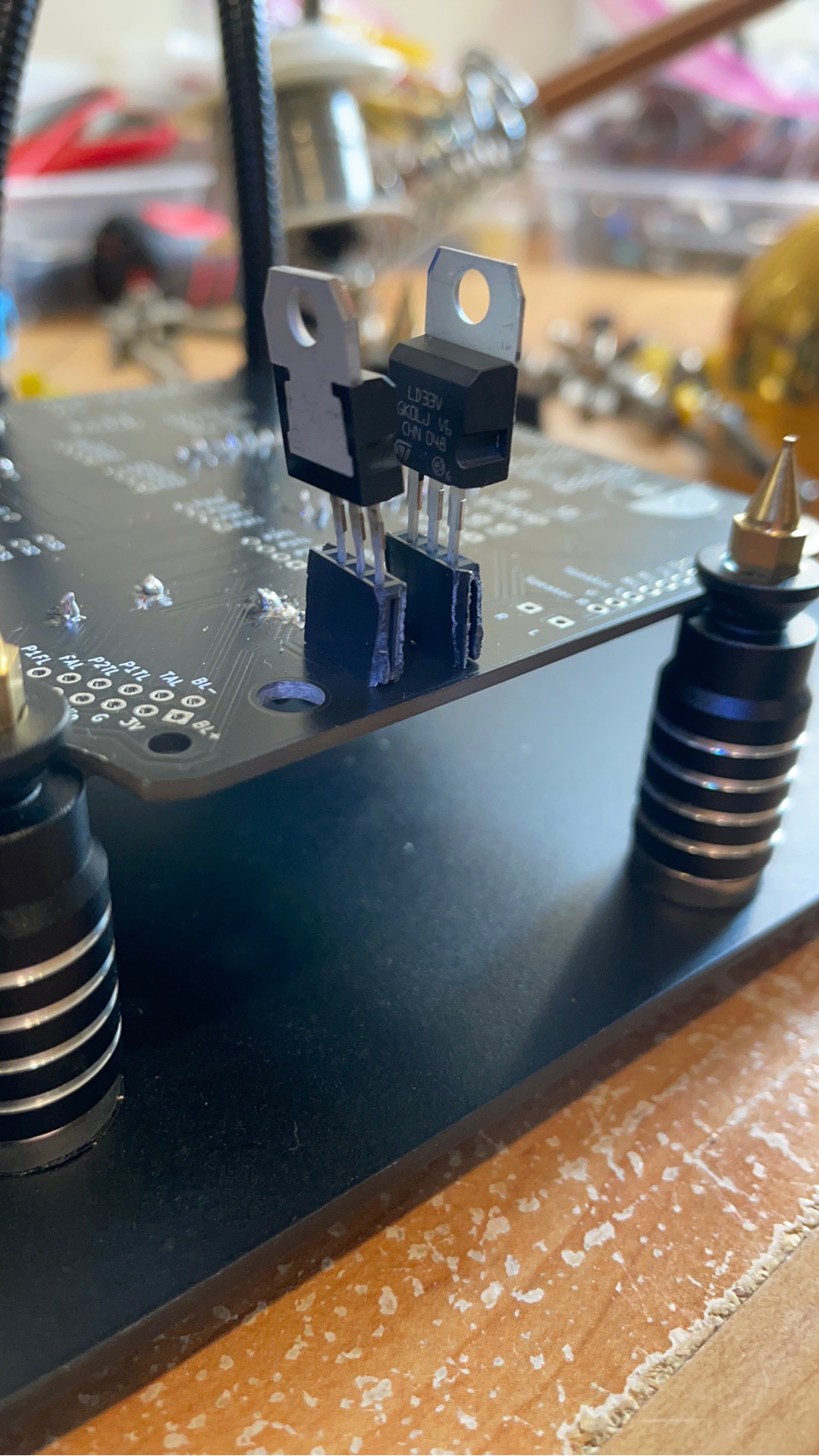
Regulator orientation
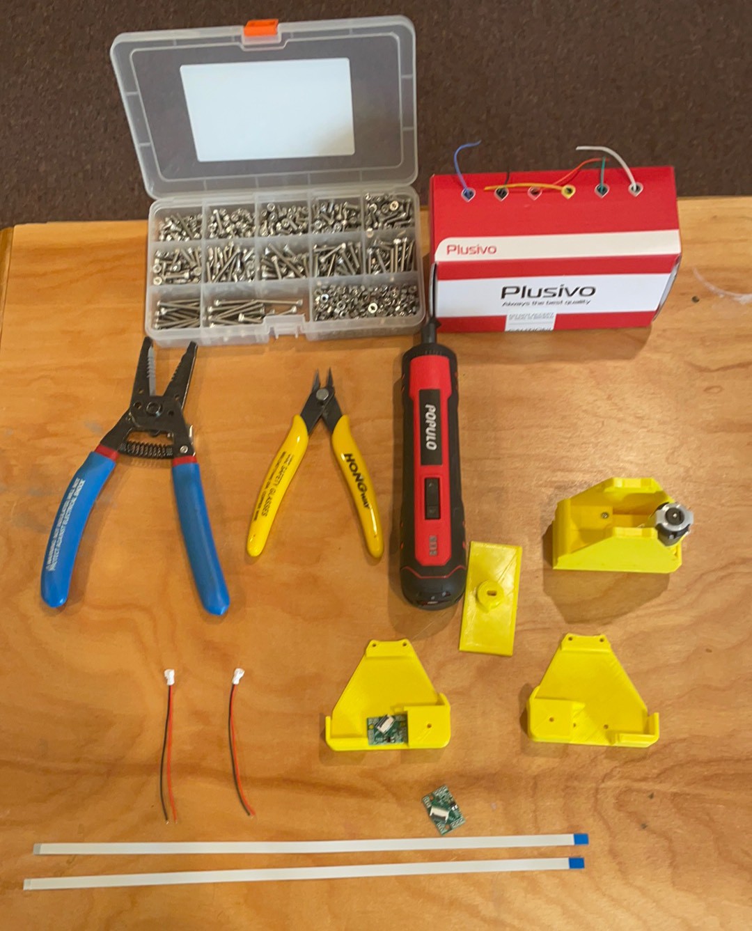
Getting ready to rumble.
-
Move or bust.
10/31/2021 at 15:36 • 0 commentsSo yesterday I got my care package from Ali Express. I have the blue metal gear motors, an abundance of FFCs and some tablet speakers. So before I jump to the next level, I need to take care of getting the basic movements from the device.
Goals
1) Define pins and movement directions.
2) Make the mapping work for 1-100.
3) Make hip motors work.
4) See if hip motor activation can make Cya stand up from a split.
First, because the PCA 9685 board is symmetric, I can put the headers on with the LED to be back or the front and it will work. However, the pin definitions are all reversed as Pin 0 is now Pin 15 compared to when I had the lead facing the board.
For the shorty, there is no Tibia so if using the C2 connector for the Femur motor the following pins needed to be activated to move the motors.
When facing the front.
Right hip Pin 8 CCW
Right hip Pin 9 CW
Right Femur Pin 4 CW
RIght Femur Pin 5 CCW
Left HIp Pin 14 CCW
Left Hip Pin 15 CW
Left Femur Pin 10 CW
Left Femur Pin 11 CCW
Broken trace next to the left hole stopped the motor from running.
-
Assembly
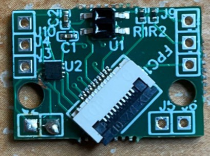
10/16/2021 at 11:52 • 0 commentsPins on top. Note Tibia and Femur locations. Silver traces down, blue spacer up.
Solder wires to motor.
Sandwich motor, sensor board and hip joint with 40 mm screws.
Sandwich from the front.
Temporarily attach with screws and solder on the wires.
Sandwich motor and board again. Slight three handed operation.
Back up one and attaché the FFC first.
Finish motor sandwich.
Put motor adapters in hip. Using one skinny and one fat.
Put top of hip on and thread the FFC through the middle.
Attach the motor wires to the Tibia board and the FFC. Screw it in the boot.
Attach motor to Tibia sensor and put the top back on. Screw it down. I do not have the right FFC here so it is not routed yet.
Boots on backward!
Turned the boot around. Should be able to test the sensors as I wait for the longer FFCs?✌️
From the back.
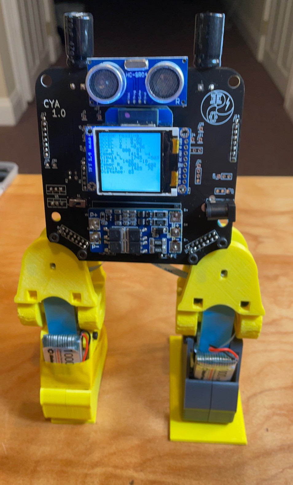
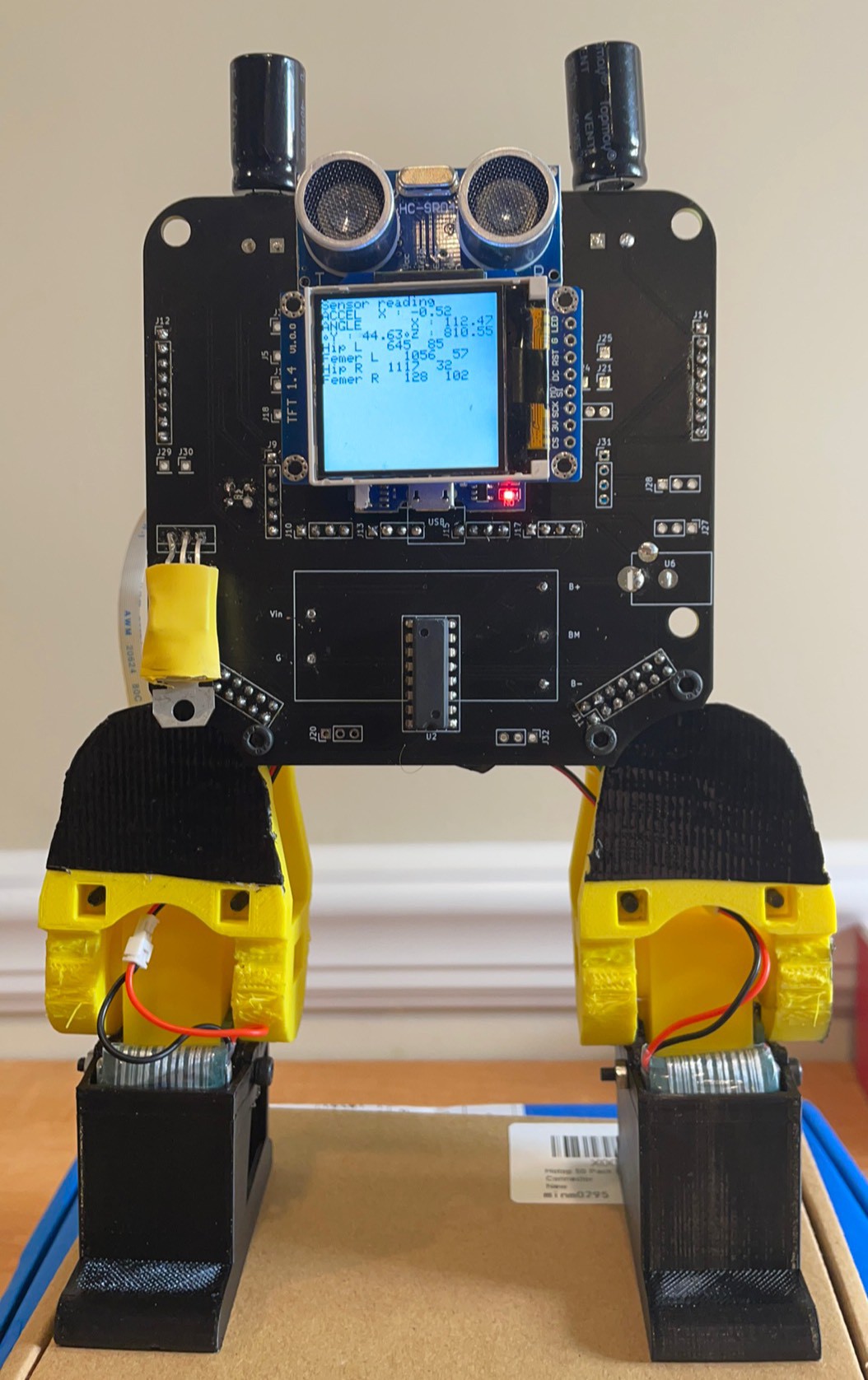
Confirming electronic function of Cya Short
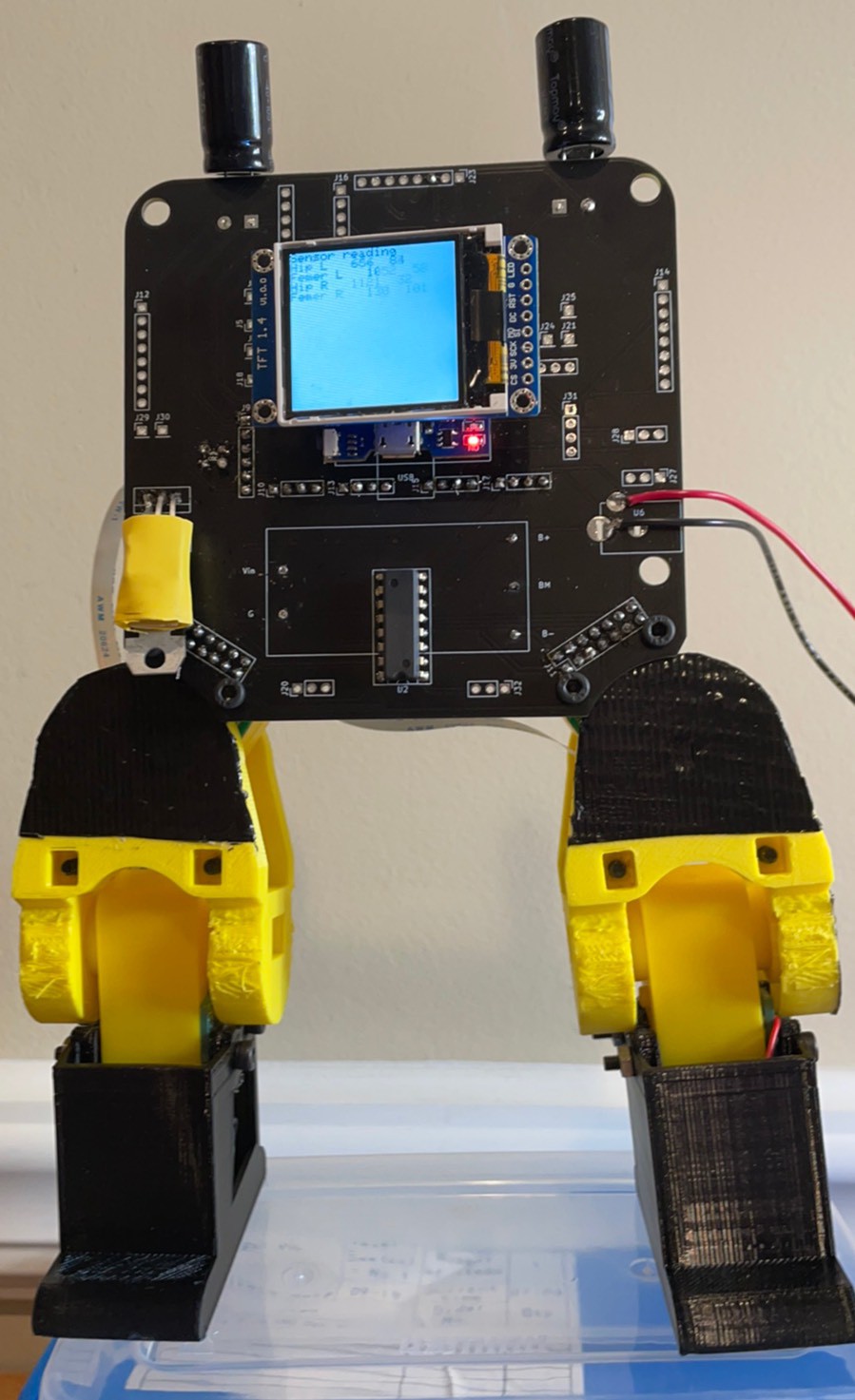
Showing x g,s and angles.
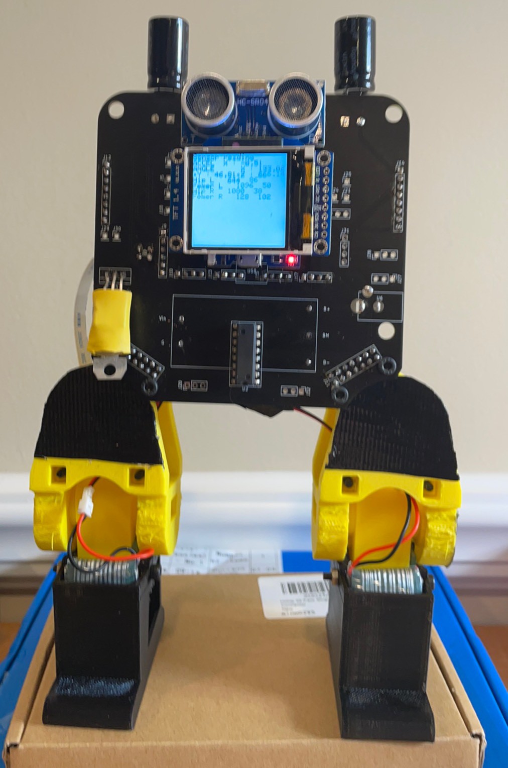
X g’s moved to 1.48
G’s moved to .34.
Added ultrasonic distance at the bottom
-
Hip Repair
10/09/2021 at 11:15 • 0 commentsIn the last log, I detailed the issues with the Femur joint sensor. The face was not in the linear range and the last half of the travel was not linear. There was a step where the gap is between the parts and the last half was not sensitive at all.
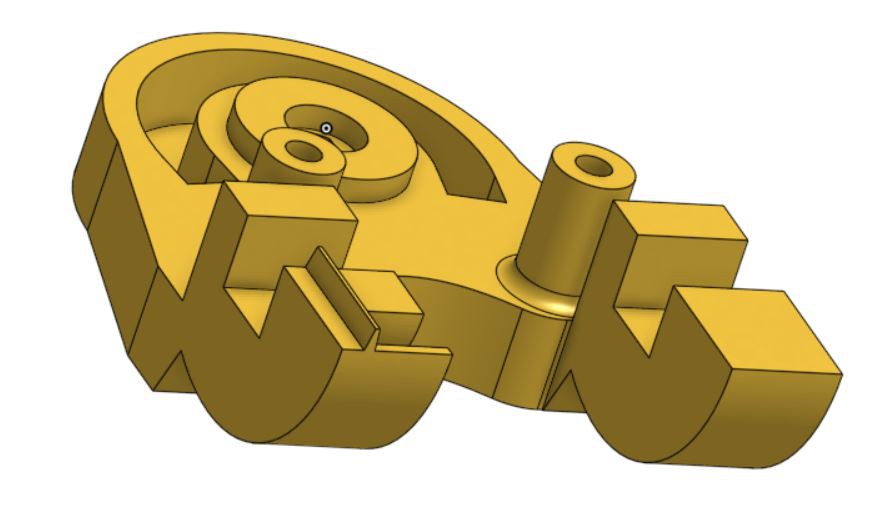
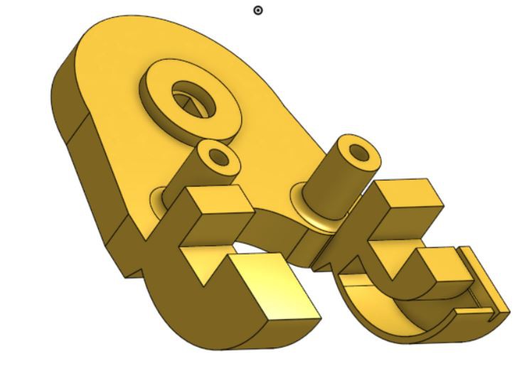
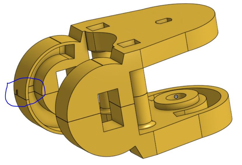
So I fixed three things in the model below.
1) Added 1.5mm to the thickness and pushed the reflected surface out by 0.5mm. This should get it more into the linear range and reduce any weird effects from the outside being too thin causing it to reflect a different color.
2) Added a tongue and groove feature to prevent a big gap from showing and causing a discontinuity in the sensor output.
3) Changed the hard stop location to increase the range of motion. This may allow Cya to be able to sit up. Presently limited to about 120 degrees total travel.
Lastly I made them symmetric because they were starting to look ridiculous.
![]()
![]()
![]()
I will get these printing and see how they work out. I will post some pictures were they are done. I made them pretty much line to line so we will see how it works out.
I also want to make full 1 pcs TPU feet. I am going to try that next.
Lastly, the hip board I made last weekend just shipped. Pretty good for a holiday week. Last week most Chinese companies were 100% shut down for the national holiday.
-
Deep dive on the sensor
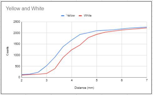
10/03/2021 at 14:55 • 0 commentsI had some basic questions that needed answering. Firstly, how linear is the sensor. Secondly, what is the optimum distance between the sensor and the reflector ramp.
For background, I am reading full scale 0-3.3V with 12 bit resolution or 4096 counts.
![]()
You can see for yellow, I have a roughly linear window from 2.66mm to 4.33. This is measured against a flat surface with cardstock as 0.33mm increments.
I am slightly embarrassed to admit took this data today, after working on the project for 9 months. When I started the project, I played with some different resistors but because the sensors were not mounted to anything it was hard to measure the distance accurately. i saw that the voltage changed a measurable amount with the resistor combination I chose and I moved forward to make some boards.
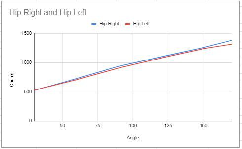
Angle measurement
![]()
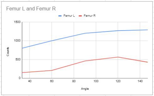
Femur measurement
![]()
Unfortunately, my first design had the white PLA too close. I played with grayscale shading on paper and had good results so I tried grey. They reflectance was terrible there was almost no change. I then switch to yellow and saw much larger changes with angle but often on the last half of the rotation. I reduced the slope of the ramp and made it a bit further away and got good results. Here is a graph showing the counts versus angles for these 4 versions.
After seeing the good response on this profile reprinted the ramp for the to the hip joint and got this response.
![]()
Now if the other axis was similar, I could call it a day but I am getting some weird responses.
![]()
There are 5 things that are different with this axis.
1) The reflective wall is printed vertically so it does not change in defined steps like the horizontal surfaces. The horizontal surfaces look like a staircase because of the layer thickness of a print which actually work quite well.
2) There is support printed in the channel and remnants may be causing strange reflections.
3) The outer wall is so thin, it looks darker from the inside as you can see the tape on the outside.
4) The outer wall is thinner than the other two parts.
5) It is made of 2 parts so there is a seam that lets light in and it reflects differently.
Looking at it more deeply, I have noticed there is a large axial play in the shaft. This axis is not trapped very tightly. This was because it was trapped tightly and I had to almost deflect the hip to put it on. I reduced the model by a mm off the adapter on each side and now there 1-2mm of play. Looking up the page at the first graph we know that we only are working with 1.67mm of liner range and being two close does not do us any favors. By shifting the shaft back and forth axially, I can change the output by 500 ticks. No wonder I had such a hard time to measure it. When I measured the left, it was biased away from the sensor, when I measured the right, it was biased toward the sensor, reducing the gap.
I also see the sensor board is on an angle due to proud solder joints. This also makes it hit the side of the wall instead of the back and bouncing off. Combine that with a little support and that might explain why the end is wonky.
I will make the shaft adapters taller again so that it is line to line. The new boards with sit flat so proud solder joints will not be a problem. I will make the part 1.5mm thicker and push out the ramp by 0.5mm. The response does not have to be completely linear but it has to be continuous. If the slope change to negative my control algorithms will not work.
Too much play
![]()
Hip joint
![]()
Part progression
![]()
-
Lots to do
10/02/2021 at 09:28 • 0 commentsWhen its 4 AM on Saturday and your dreams are you punch list, there nothing to do but get up and live your dreams! I have some interesting challenges to work through this weekend.
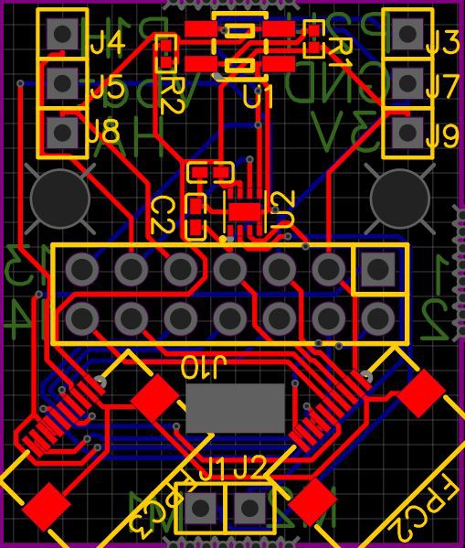
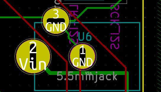
1) Remake the hip boards with the correct pinout on the header. Add better silk screen. Check for the stock of the less expensive motor driver. Order the assembled hip boards. Order the longer FFCs from Aliexpress. Fix the connection on the brain board to the 2.1mm plug. The ground and Vin are reverse which would not make for a good day. I should make the files available for the boards incase anyone feels ambitious.
Well I used the auto router for the first time in Easy EDA. The last auto router I used was on Eagle and it was not great. I then changed to Kicad and it does not have one native to it. So I was shocked to see the following really nice layout.
![]()
The only thing I will change is the bottom trace that goes close to the mouse bites.
I confirmed I need a B type FFC with pins on exposed pins on the opposite sides.
The pin layouts are updated here.
Files I used to order the boards are also in the file list.
I also tried publishing it on the Open Source Hardware Lab.
The integration is super smooth between Easy EDA and JLCPCB. It is not so important for bare boards but for PCBA assembly, I do not think I will go back to Kicad. If you have a self made footprint. I am not sure how you would upload it. They need a footprint defined in the BOM. I am not sponsored by JLCPCB but I will shill for them anyways as it is so cool to see the minute by minute progress updated live. I have ordered populated PCBAs now 4 times and 8 days later I have been getting them. This order is about $3 each on a quantity of 20 and half of that cost is components.
For the Jack output I swapped the power and ground that were mistaken. When I created the symbol I made the pin numbers differently than in the footprint. Power should be at the back of the Jack.
![]()
I put the archive file in the files section for the Brain Board. I am still struggling with libraries although I did archive the libraries before I archived the project. I will have someone try to download it and see if they can do it without getting library errors.
2) In depth study on the encoders. Answer the following questions.
a) Graphically compare the output from before and after I moved the ramp out by 2mm.
b) Look into the femur joint which does not have a linear second half.
c) Investigate if tape color will change the output. The tape blocks the outer light to make it more repeatable but may also affect the reflection.
d) For counts over 1000 should I pull the ramp back a bit? Remodel, print and retry.
e) Make sure the Onshape model is updated with the latest parts.
3) Debug the issue with the batteries, BMS and regulators. Presently the regulators drop the voltage to 1-2V when used with batteries in series and the BMS. DC power supply voltage is fine. I expect high frequency effects are tripping the regulators. Maybe when Doug comes back from vacation he can look at it on a scope. For now I will breadboard it and reproduce it to ensure it is not a layout problem. I will then add some capacitors to see if I can filter it out. Last resort is to swap out regulators or the BMS until I find a combination that works.
4) Solder up a new flex to replace the one I put a screw through last time. The goal is to get a robot working with each leg operational in each direction. First thing I want to try is to make it stand up. To make it pop up from full splits, just using the hips. Next would be to get to full splits from lying on its back. I can hand manipulated it to do it but I am not sure if the motors have enough power to do it. Additionally I would like to see if I can use the 1:48 motors to do these things with the new higher voltage. This would so much improve the accessibility.
5) Once I have all the joints working and the encoders debugged, it is back to implementing closed loop proportional control of the joints. Once the basic motion is covered, I want to be able to use the robot itself as a teaching pendant. You could record key points by manipulating the joints to points in a sequence and then the firmware should be able to replay the motion. Bonus points for a com interface where it would output the key point sequence for future programming references. This will unlock the power of this servo motor configuration. Each motor has an absolute encoder and the position can be checked at any time. This is a very high end feature for servos.
6) By now I am well into next week/month but I would like to fine tune each of the joints mechanically. Make sure I have the right range of motion. If I could increase the motion of the femur joint I could sit up which would be nicer. In any case, I should make deliberate decisions on the range of motions and limiting geometry on each joint. I should republish the files in STP and IGS format. I would like to update the Onshape assembly and then bring it into Solidworks. In Solidworks I can make some more fluid animations. I should also work towards tutorials on how to model each part in Onshape, Solidworks and Freecad.
Future work:
Micropython - Doug has worked through the modules. Work through his tutorial and publish.
Native C - Ground up programming.
Accelerometer and balancing - Include the accelerometer in as active control for balancing.
Voice control - Get the microphone working with a wake word.
Voice confirmation - Set up canned responses and get Cya to reply to commands.
Arms - Implement a backpack with the the motor controllers on the back and smaller boards with sensors and FFC connections.
Second set of legs. - Make the seconds set of legs to make this a quadruped. Once the BMS/regulator issues are worked out this should be a subset of the existing brain board. Just the lower half with the top board to board connector.
Now that I have outlined a years work of work, I should quit dreaming and live my dreams!
-
Lessons Learned
09/27/2021 at 10:17 • 0 commentsI have a friend that has been telling me that is not what I do that is important but it is what I learn. Well I thought I would explain the three things I learned this weekend in 20 hours of robotting.
It is not always the things that you worry about that bite you.
My boards came in as planned on Friday night and I was ready to assemble.
I was worried about 3 things. First that the FFC would not be tight enough in the connector and they would fall out as the legs moved. - Absolutely no problem on this point. The connectors were great and I could use the FFC as a handle to pick up the robot. - No problems here.
I was worried about the 0.5mm pitch FFC not having enough current capacity. I connected the wires and got a toasty FFC. Then I realized that I had designed in the B type connections and the pins were reversed. I changed the FFC to the one with pins up on one side and down on the other and this took care of the heating - No problems here either.
The third thing I was worrying about was that I was regulating 3.3V and 5.0 and putting them both into the ESP as inputs. I usually only put in 5V. It seemed that in the end, it would with both 5V input and 5V and 3.3V inputs so it was wasted cycles thinking about it.
I hooked up the batteries in series, got my 8.2V at the BMS output and I thought I was off to the races. I soldered in the 7805 5V regulator and the output at the BMS dropped to 2.0V. I thought I burned out the BMS and I took it off the board and it still worked. I put a new one on and got the same thing. I cut off the regulators and everything worked. I tried the regulators separately and they worked. I tried with just the 3.3V, double checking the pins because it is different from the 5.0V regulator but nothing there. It did not work when it was on and worked as soon as I removed the regulator. I finally removed the BMS and ran voltage from a power supply at it was fine. I put the BMS back on and it was still fine. I tried with another different type of BMS and it did not work with batteries but did work with external voltage. My conclusion is the BMS and the voltage regulator do not play well together. I guess I will just have to find some that will. The big take away is I need to breadboard more.
The second big lesson came from the next step. I decided to go forward with just the power supply and to finish the debugging. I then found this issue that ended my run with the new boards. My pin definitions on side of the header were different from the other. On the brainboard I was using Kicad and on the hip board I was using Easy EDA. On footprint was using alternating pins and the other was running ccw so even though the schematics looked the same, the pin definitions we totally different. My end pins worked but the ones in the middle did not. Game over, time to order again. The big lesson is a I cannot skip the excel sheet showing the pins on each connection. Also, no more ECAD at one in the morning!
Well I still had some closed loop programming to do and newly printed hips I was dying to try out so I went back to the Flex circuit design. I decided to run with a power supply and I tapped in a 7805 5v regulator to the 5V and ground line. I think ran wires down to the flexes from the input and now I had adjust power for the motors only and a stable 5V for the rest of the circuit. I conformal coated all the flex connections with hot glue and got on with the assembly.
The new prints with deeper pockets worked OK but there are difference between joints that I can not yet explain. I will do a more detailed log with some plots and consider it more. I put a screw through the left legs flex in assembly and lost movement of the left femur but over all I had something to work with. Putting in variable voltage makes it exciting. The joints move fast and with great power. The down side is you can strip the motor shaft/gearbox shaft connection.
And because some movement is better than none, here are some of the comical wild flails of Cya.
-
Stand up and walk!
09/25/2021 at 12:07 • 0 commentsMaybe I should first target moving the joints with a repeatable motion.
To get there here are the logical progressions.Confirm the correct voltage is running through the system.
I made some big changes with regards to voltage management. The batteries are connected in series to the BMS that is on the main board. Previously I had a battery charger on each leg which pumped the battery voltage to 5V. This round with the batteries in series, 8.4V is regulated down to 5V and 3.3V to run the lower power processor and sensors. The native 6.4 - 8.4 Li-PO battery voltage is applied directly to the motor drivers for minimum losses and maximum power. The concerns I will have to investigate are:
a) How much does the battery voltage degradation affect the motors?
b) Is it going to be important to monitor this voltage and how can I do it? One idea might be to connect the switches to a parallel circuit to the main battery voltage and have them normally closed.
c) I am sending regulated 3.3V and regulated 5.0V into the ESP. I have only done one or the other in the past and I am not sure if I am going to blow up the regulator on the board. I read that the regulator on the board does not have enough current capacity to allow the ESP to run WIFI which is why I am running 3.3V as well as the 5.0V but this makes two 3.3V sources to the same power input to the ESP. For now, I will hook it up and hope for the best. If my ESPs start blowing up, I will remove the 3.3V pin on the module.
Hardware Debug
1) Get all the power components in place.
BMS - Check
Leg headers on board - Check
Leg headers on hip board - Check
FFC to leg boards - Check
Connect batteries to Tibia board.
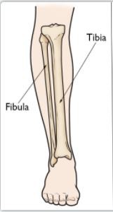
(I just realized I named by lower joint as amalgamation of the Fibula and the Tibia. I called it a Tibula. I will go back to Tibia)
![]()
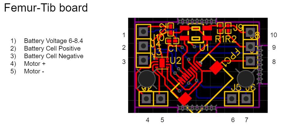
I need to but more silkscreen labels on the board next time. To help with understanding, I made a pdf which all the pin definitions for the legs. I remembered one key point. This robot will only work with B type FFCs where one end has the exposed pins up and the other has the exposed pins down. It essentially transposes the pins in the cable. I designed for it, forgot about it and rediscovered it in my QC of the boards upon receipt. Now that the world is straight and I know which pins to connect the battery to, I can go about confirming the power layout is going to work. Here is the layout. Pin 2 is Battery + and Pin 3 is Battery -.
![]()
2) Once power is measuring good, add the ESP and make it blink.
3) Add the screen.
4) Add the PWM board.
5) Read some sensors.
6) Move some motors.
Choose your own adventure bot
Ultra low cost 3D printed Open Educational Resource Walking Robotic Platform