Close
0%
0%

Hardware Data Logger

Easily extendable data logging platform featuring STM32F103RBTx, WiFi, microSD storage, LCD with four buttons, UART, and pulse counters.

Public Chat
Similar projects worth following
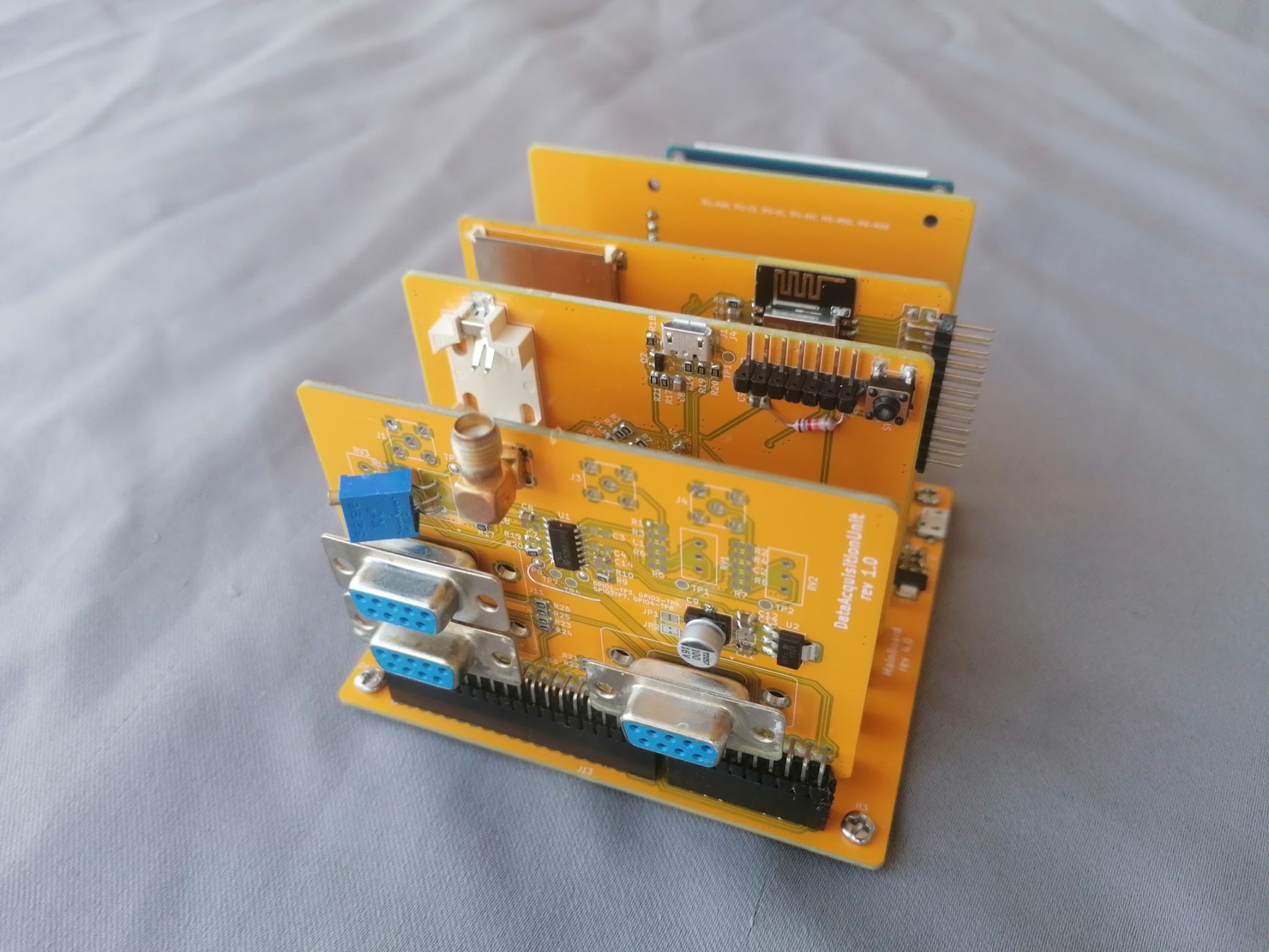
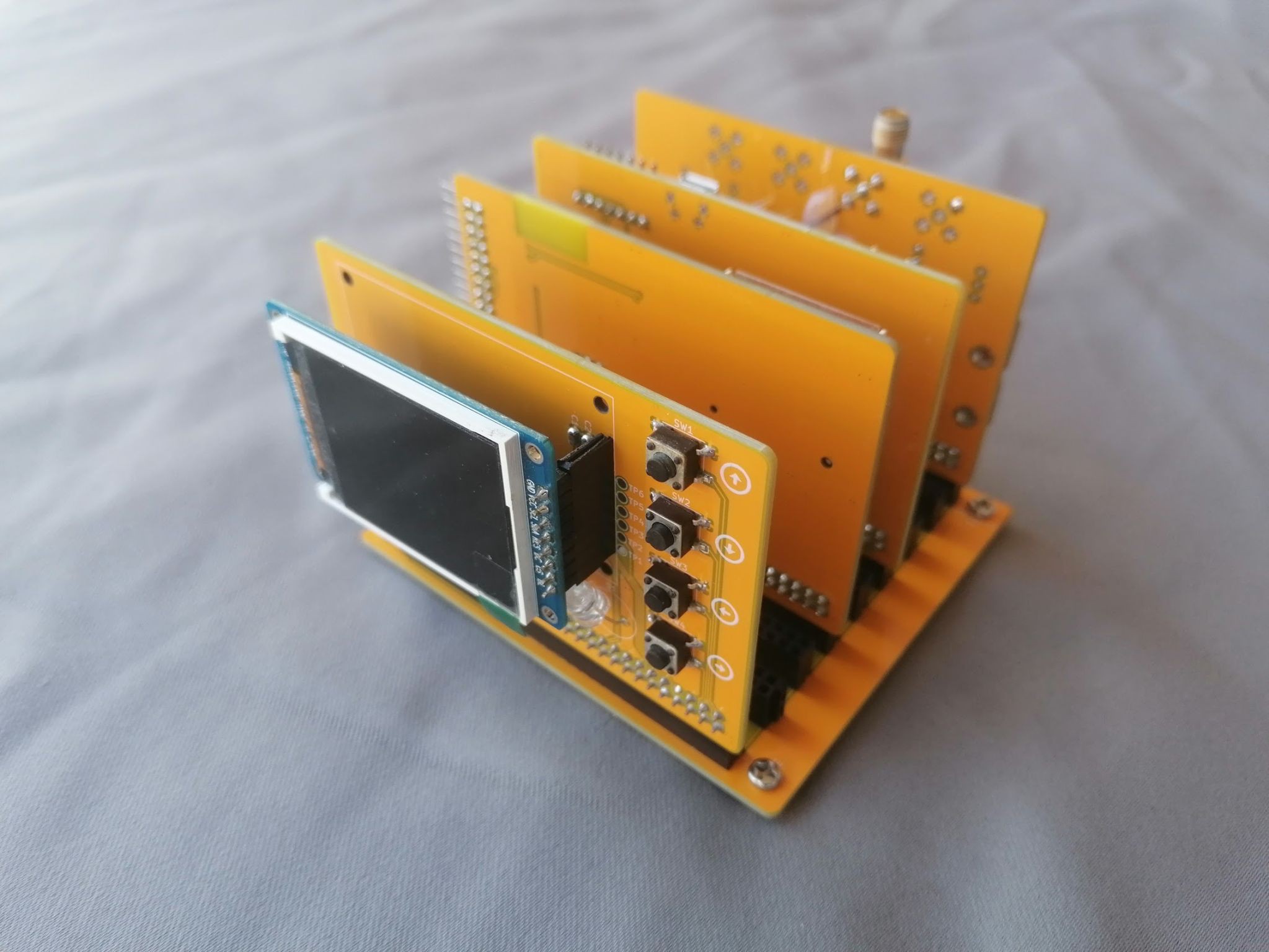
• Modular and Reusable Design: The mainboard features multiple connectors connected in parallel where cards are placed. These cards are used for data acquisition, handling, and storage, but other cards can be added as needed. For example, if a larger MCU is required to handle more processing, only that specific card needs to be replaced, saving time and money.
• The device uses cheap, easily accessible components and is easy to build.
• High-level logic (e.g., layouts with data presented on the LCD) can be completely developed, tested, and visualized on a PC simulation, which is a build variant.
• The development environment is containerized in Docker, meaning faster setup and no need to install tools manually.

GitHub: https://github.com/RobertGawron/HardwareDataLogger/develop

Hardware

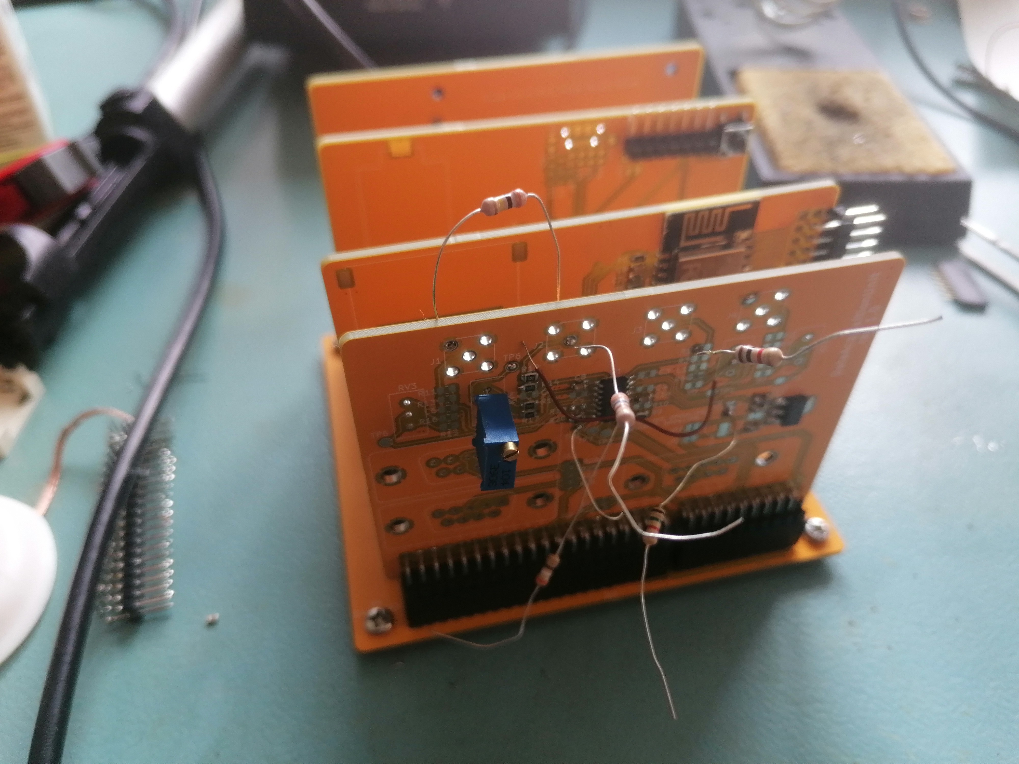
Due to the availability of low-cost, high-quality PCB manufacturing, home-etched PCBs have become largely obsolete. While the PCB design for this project may be difficult to etch at home, it is still possible. Subparts of the circuit can be assembled on a breadboard, making the process much easier, and the modular software design allows for easy reuse of these components.

Software

NUCLEO-F103RB Board

The NUCLEO-F103RB serves as the main microcontroller, handling data acquisition, processing, storage, and user interaction. In future iterations, the NUCLEO-F103RB will be replaced by an STM32 chip directly integrated onto the PCB.

  • Toolchain: C++17, C, STM32 VS Code Extension, CMake.
  • More info.

ESP8266

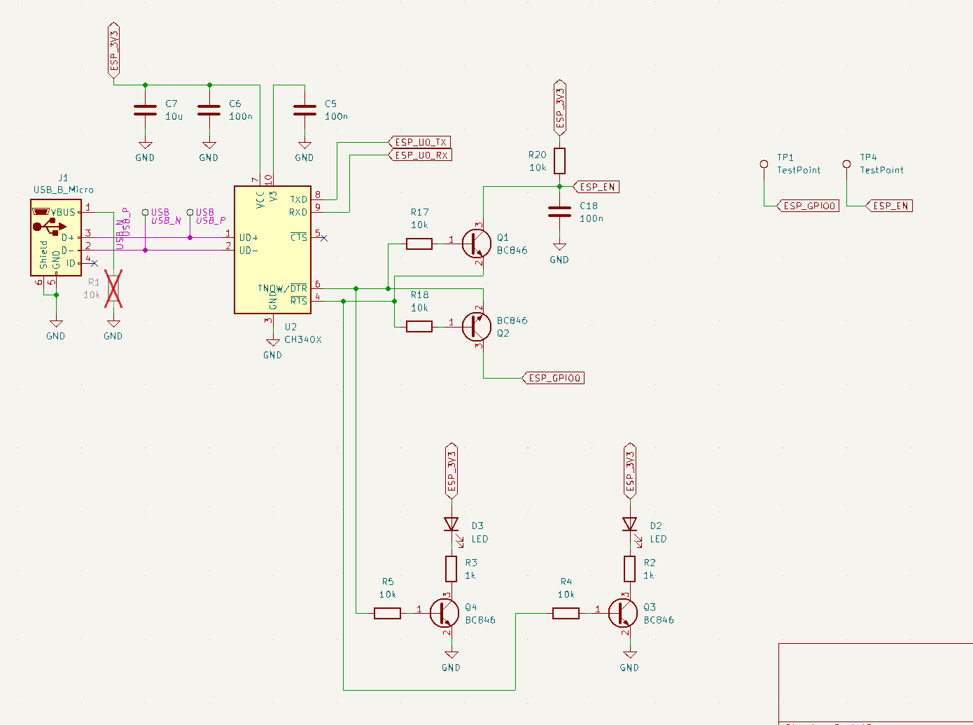
The ESP8266 is currently used for data transfer via WiFi and will support FOTA (Firmware Over-The-Air) in the future.

  • Toolchain: TBD, currently using Arduino IDE.
  • More info.

DevOps

It's good to let the machine handle the tedious work of checking code quality, freeing up more time for the useful and interesting parts of software development.

  • Toolchain: Unit tests (Google Test, Google Mock), code coverage (LCOV), static code analysis (Cppcheck), dynamic code analysis (Valgrind), Docker (for both local development and CI), GitHub Actions (CI).

Simulation

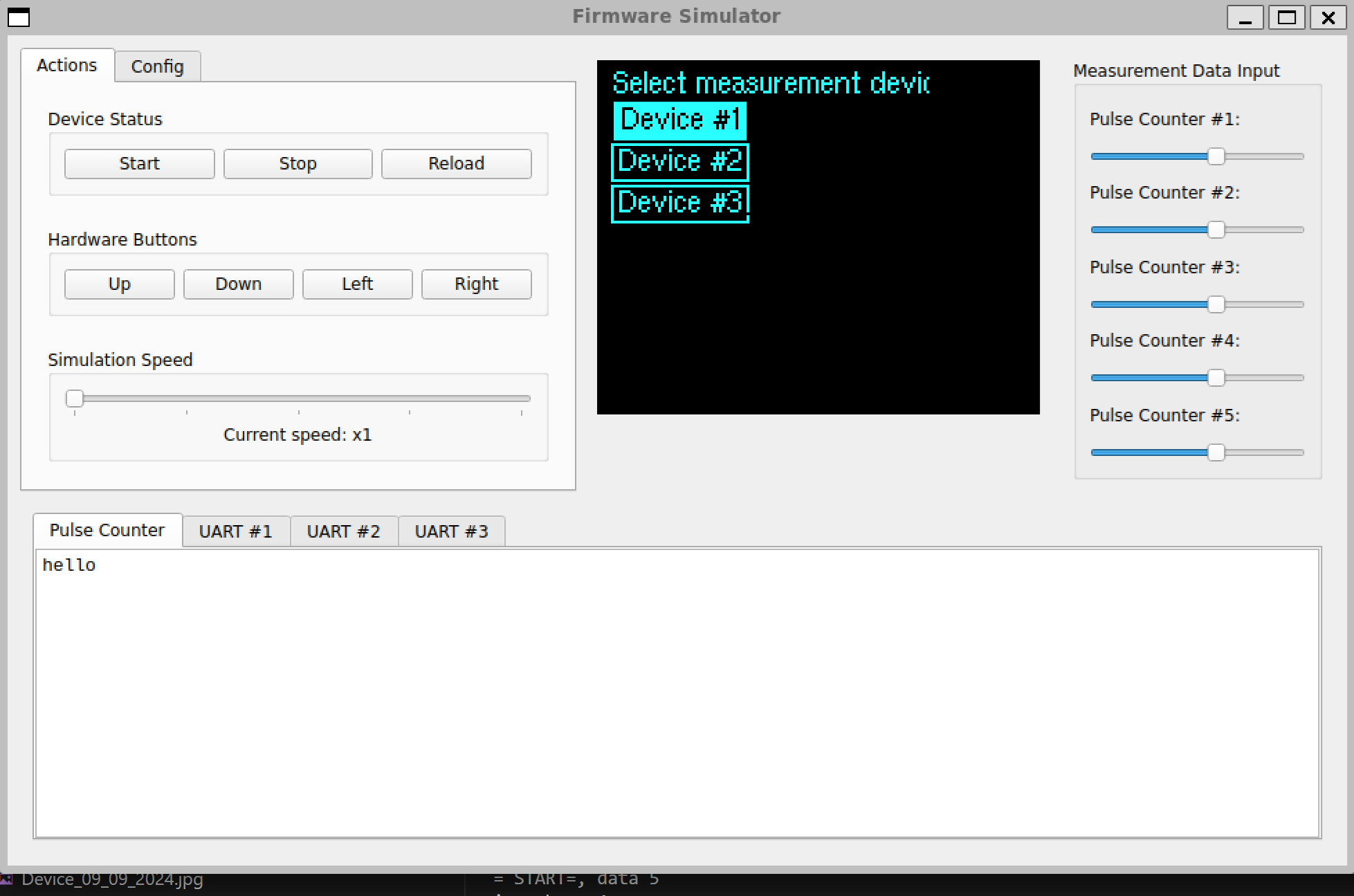
Embedded development is cool, but constantly flashing the target device for non-hardware-related logic, like the human-machine interface, can be time-consuming and frustrating. To streamline this, a simulation was developed that isolates the firmware not directly tied to hardware, adds stubs for drivers, and includes a GUI. This allows all high-level aspects, such as what’s displayed on the LCD, user interaction via buttons, and data parsing, to be tested without the need for hardware.

While this simulation handles the firmware, speed of execution isn't a concern since it focuses solely on high-level logic. For hardware or driver-related issues, traditional methods like using an oscilloscope or logic analyzer are still necessary, as the simulation cannot be used.

Below is a screenshot from the simulation. Note that this is from an earlier version when the device was designed to work exclusively with a Geiger counter. The current simulation doesn't work.
Documentation

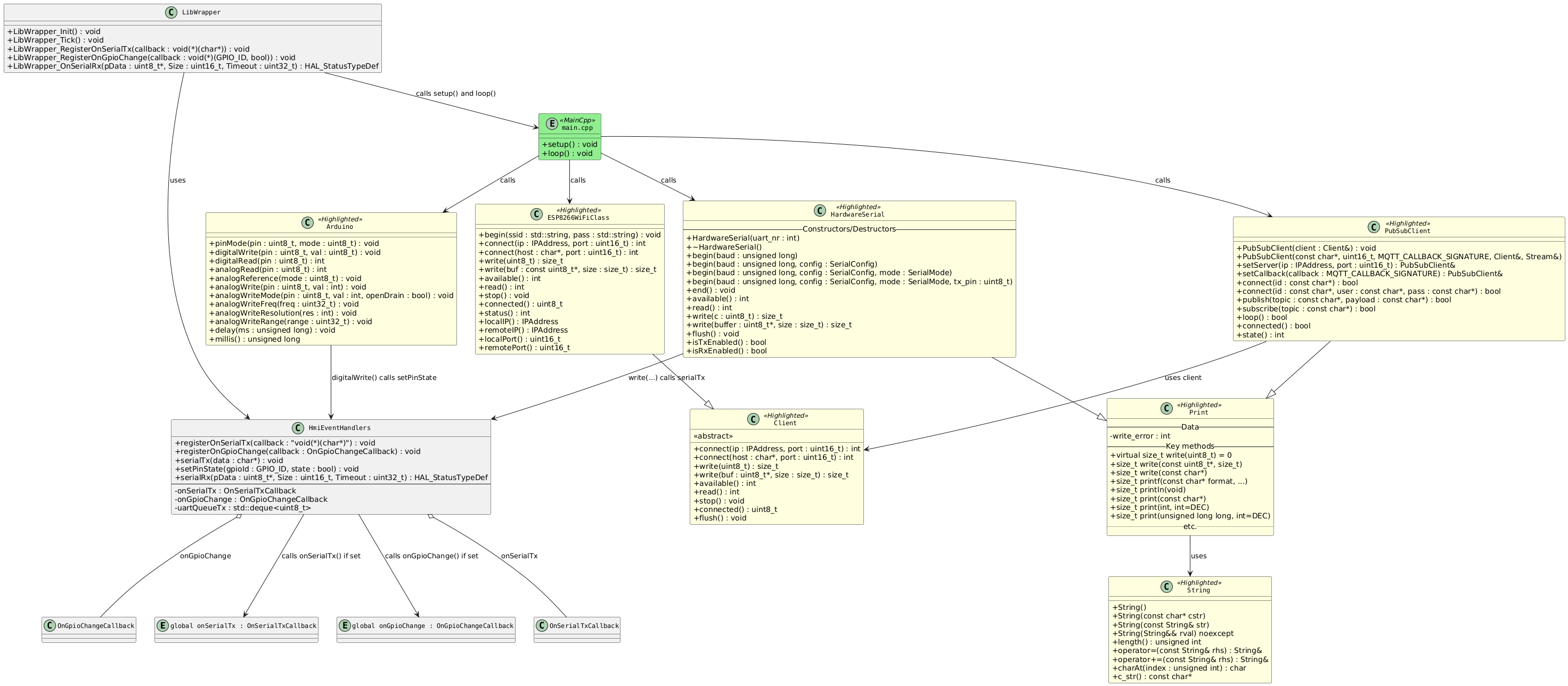
UML diagrams will be added later using PlantUML.

  • Thoughts on Display Libraries and Text Rendering

    Robert Gawron3 days ago 0 comments

    When I searched for a library to handle the ST7735 display in the project, every link in Google pointed to stm32-st7735. The library itself is simple and easy to use, and it has this nice function in its API (slightly modified example from the author’s blog):

    ST7735_WriteString(0, 0, "Hello World", Font_7x10, ST7735_RED, ST7735_BLACK);

    This method sets the initial position, text to display, font, and colors, making it easy to display some data and get things started. However, later on, it's easy but not really good:

    • Fonts are hardcoded in the library: Changing the font requires modifying the library itself. I'm not a big fan of this because it usually means that either I’m doing something wrong, or the library has limitations.
    • PC simulation problems: I plan to have various layouts to display data and allow the user to configure the device. Constantly flashing the device to test layout changes takes time, so a PC simulation would be great. However, the binding of high-level logic and SPI data-sending (the chip driving the display is quite complicated IMHO) makes it tough. One option would be writing an SPI HAL driver (the one generated from CubeMX) mock to extract data, but that’s a complex task.

    Fortunately, the library also includes this method:

    void ST7735_DrawImage(uint16_t x, uint16_t y, uint16_t w, uint16_t h, const uint16_t *data);

     With this method, font rendering can be managed directly in the user code and passed through ST7735_DrawImage, so the library doesn’t need to know about it, it just do it's work to ONLY send the buffer to the display's chip

    No high level logic not related to being a driver library. For a PC simulation, the entire library can be mocked, making the extraction of display data easy. I have the *data with the pixel content and x and y with the position I can just store this and then present it in my app (see the screenshot in the project description).

    Even more, yesterday I found another library (ironically with the same name) for handling this display. It also has a similar method but is written in a much cleaner way. I’ll use it instead but the idea stay the same.

  • Turning KiCad Designs into Realistic Renders with pcb2blender and Blender

    Robert Gawron6 days ago 0 comments

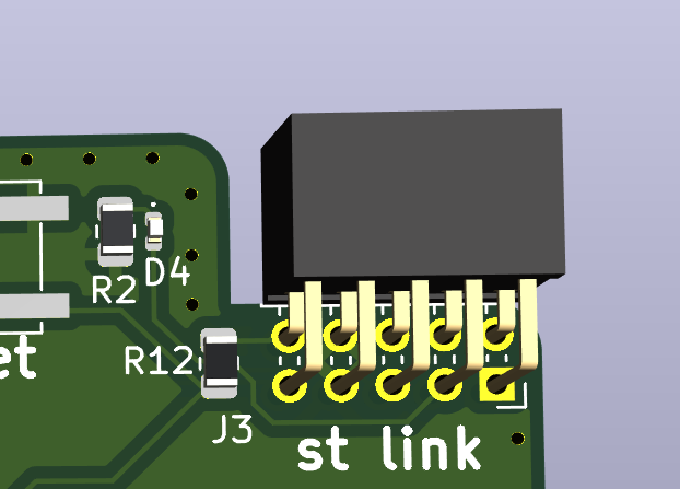
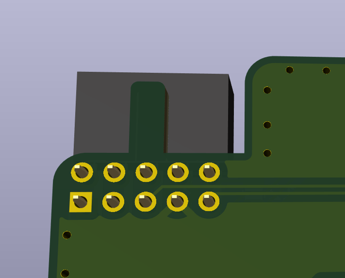
    Recently, I found a great open-source tool for creating realistic PCB renders in Blender, and I decided to try it on my project. The tool is pcb2blender, and you can find its GitHub page in the link, which includes installation and usage instructions. You just need to install its plugin in both KiCad and Blender. Usage is simple too, you export your project from KiCad and import it directly into Blender.

    What’s awesome about this tool is that it automatically assigns textures and even adds tin to the pads, making the PCB look like it’s actually soldered. I tried Blender a couple of years ago, and it has this weird way of handling textures by connecting blocks, kind of like programming - it’s interesting, but I didn’t like it (I’m not really into graphic design). With this tool, though, you don’t have to deal with any of that.

    There are still a few things you’ll need to do manually in Blender, like adding light sources, setting up a background, and configuring the camera. However, I managed to figure it out in one evening, so it’s pretty easy.

    Below, you can see some of the renders I made. They’re not perfect since I’m new to Blender, plus I limited the rendering samples to speed up image generation, so the output’s a bit noisy.

    I’m really impressed with this tool!

    Design of below PCB is not finished.

  • Diving into CMake and Docker (and a few other tools)

    Robert Gawron09/29/2024 at 18:48 0 comments

    Last week, I was working on cleaning up the CMake files and setting up Docker. It was quite difficult because I don't know either of them well, but in the end, it works pretty well.

    Personally, I really like the idea of Docker because, in a file, you can configure your environment and - here’s where the magic is - this file is treated as configuration/code. Meaning, it’s parsed and checked by a machine. It’s not a README that’s never up to date, but something that gets “compiled,” and you get errors if something is wrong. Some DevOps guys would probably laugh at this description, but it’s true :)

    I’ve also experimented a bit with hpp2plantuml, a tool to generate UML class diagrams based on existing code. I wasn’t happy with the results as it omitted a lot of connections that exist in the code, but the setup is easy, and what it generates is accurate (it’s just not complete). I even have a build for that!

    Another tool I checked out is include-what-you-use. Setting it up isn’t trivial, at least on Linux, as it needs to be downloaded and compiled manually - the old-school way. It also requires, AFAIK, Clang as a compiler, meaning you need to have a build version using Clang. I haven’t yet paid much attention to what it generated, so I can’t say if it’s useful for embedded projects. BTW, it was developed at Google.

    I also removed the build for Valgrind because I intentionally don't use either the standard library or dynamic allocation, so it was kind of silly to include that tool.

  • HW rev3.0 (but the project is still unfinished)

    Robert Gawron09/14/2024 at 13:00 0 comments

    I have made a new version and it was working (well, not all of it was/is working but major parts yes). This is also the first time the project has its PCB so it looks much better than previous version.

    What you see is NUCLEO board (white PCB at the bottom), my PCB (red one) and the LCD with its own blue PCB (LCD comes with this  blue PCB but I think that maybe I will desolder it and solder it directly into my board, I don't know).

    The NUCLEO and the logger PCB are connected via SMD pin headers that.. I forgot to buy. I've used standard troug-hole pin headers, but I didn't solder them quite well (it's a different footprint) and that make a lot of problems with missing connections. I've sped three hours at least on that.

    ESP8266 and STM32 talsk to each other via UART, that's make me happy, that was my main goal for this version. I can dim the LCD, although the algorithm is rather primitive. Buttons works too. I will add debouncing in the software later.

    The LCD doesn't work now, probably because some pins did unconnected again, but it was working so I know that HW design is good. Same with SD card.

    I won't have access to my tools, so I made a small PCB with an SD card and a connector for the LCD display to overcome the current problems with the PCB. It's based on the existing Arduino shield, fun fact it's red too. 

    I tried to use a lot of modern features in the code (which doesn’t compile, by the way). I have unit tests (Google Test, Google Mock), static analysis (Cppcheck), and dynamic analysis (Valgrind, though it doesn’t really make sense for this project, but the diagrams look cool). I’ve got test coverage, and I’ve also added docs and docs coverage. The downside is that CMake (yes, I’m using CMake now too!) looks like garbage. I’ll have to take a look at that.

    I’ve switched to Visual Studio Code. It’s 2024, no more Eclipse-based garbage.

    What do I plan?

    I want to get rid of the NUCLEO board and use the STM32 chip directly on my board. This will solve the connector issues and make the device smaller and cheaper.

    My second goal is to use Grafana for result visualization. It’s an awesome open-source tool for displaying measurements, with a web API, and it can run on a Raspberry Pi.

  • Draft of support for ESP32

    Robert Gawron09/03/2021 at 12:57 0 comments

    This is the latest hardware version (rev 2.0). The ESP module has been added, and it has been successfully flashed. Several hardware changes have also been made to the PCB design.

  • SD card support

    Robert Gawron08/30/2021 at 20:49 0 comments

    SD card works OK, here are interesting things that I've learned:

    • There are two protocols to communicate with SD card - SPI (slower, but easier) and SD bus, some cards will not work with SPI
    • The SD card can draw up to 100mA when writing data!
    • As usual, it's good to add small resistors in series to all pins that are accessible from external, user can insert or remove card, so all data ports can be considered to be accessible from external. This is to prevent ESD damages. For SD card those resistors are in range 40-50R.
    • It's good to add pull-up resistors to all data lines, otherwise some cards will not work. There are chips on the market with pull-ups and in-series resistors.

    Info from: [1], [2]

    The prototype is now a bit bigger than before, because I've decided to cannibalize data logger board for Arduino - back when a shipment from China was for free (in Europe) I'v bought a couple of them - just in case. I don't really need therm since I don't do a lot of Arduino, and this saves me on buying SD card slot and RTC clock. I will add an RTC clock to the design. 

    The SD slot was a bit problematic, finally I've de-soldered it to see bottom side and how the card is really connected. It's weird for me because they didn't ignore pin #9, it's accessible even when AFAIK it's unused. So the pinout is like this 9, 1, 2, ..., 8, extra pins for check write protection. 

    In the next step I plan to setup ESP32, it will involve probably soldering new breadboard to the prototype :)

  • Reduce amount of elements on PCB, but keep functionality

    Robert Gawron08/27/2021 at 16:39 0 comments

    I've got a small success in  reduction of  amount of components on the PCB, I tested it on the breadboard -presented before- and i works fine.

    First, I tried to remove the pull-up resistors for switch buttons, below is the original diagram. BTW note that on this schematic there is no low pass RC filter, the filter is used for key de-bouncing, it's used in many open hardware projects, but this can be done in software too.

    Below is actualized version.

    This is possible because STM32 has possibility to configure GPIO as having internal pull-up resistor (it can be an internal pull-down too), so this resistor is still on the schematic, but now I'm using the one build-in into the microcontroller.

    Below you can see it on CubeMx.

    Note: I still didn't decide to which GPIO connects the key-left and key-right, so those are not configured.

    Another IMHO cool optimization is in setting the brightness of the LCD, originally I've planed to use discrete solution that would be driven by PWM.  The ST7735S LCD module has a separate pin for LCD brightness, I was thinking that the actual current for backlighting is needed to be provided to this pin. This is not true, it's just a logic signal, that goes to the SOT-23 chip on ST7735S. 

    The previous version is presented below.

    All the bottom part might be removed, because very little current is in real taken from GPIO port and there is no need for buffering transistors Q3, Q4. The buffering is done by small chip on the LCD module. Below is the current version.

    I've also been able to communicate with the LCD.  Fun fact is that initially I used this lib for ST7735S, but I didn't notice that it's for 80x160 displays. Mine is 128x60. Fortunately, I've found this lib for ST7735 - this one handles my LCD well. From the other side, invocations of HAL functions are a bit hardcoded with business logic, so in order to bring my PC variant for simulation of the device to live, I will have to do a bit of refactoring. 

    My next steps will be checking circuit for SD card.

  • Bread-board circuit for testing LCD and keyboard

    Robert Gawron08/25/2021 at 14:51 0 comments

    I've created a draft of the device using bread-board to check if I correctly connected LCD to stm32 nucleo and to have something to do driver development before ordering PCB. In addition I've added to the board up/down/left/right keys.

    Connections changes to original schematic:

    LCD connection:

    • RST - PC7
    • DC - PA8
    • CS - PB2

    Keys:

    • up - PC3
    • down - PC2
    • left - PC14 (TODO: move it somewhere else)
    • down PC15 (TODO: move it somewhere else)

    I've also tried to solder the part responsible for dimming the LCD but having only MOSFETs in SOT-23 package, it seems to much to work.

View all 8 project logs

Enjoy this project?

Share

Discussions

Does this project spark your interest?

Become a member to follow this project and never miss any updates