 Robert Gawron
I've created a PC simulation of the firmware to test high-level logic (mainly how data is presented on the LCD) without the need to take time to flash the device. The idea was to organize the code into layers, taking the high-level layer as is, without any modification, while providing mocks for all low-level code (mainly drivers using peripherals like SPI, UART etc).
I've implemented it in such a way that CMake takes all non-hardware-related code along with mocks and generates a .so file (a shared library). A Python application pilots this library as a real microcontroller would and gathers data about what the library does (e.g., what it displays on the screen). All is in Docker of course :)
Here's the simulation in action: in the center of the GUI, the LCD content is visible, showing what firmware renders on the LCD. The content in this example (firmware is not done) is not impressive - just a green line in the corner - but it works!
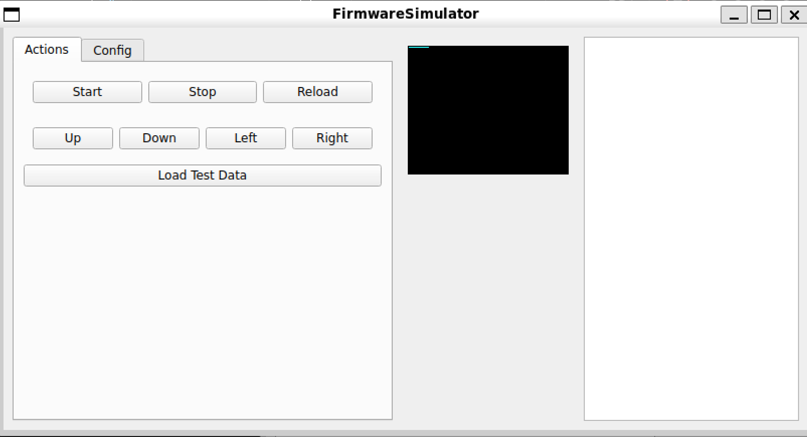
The GUI was built using PyQt6. In the original version, I used some graphic tool (I forgot its name, and Qt has many graphic tools), but it was a disaster due to how complicated it was. In this version, I took a picture of the old GUI and asked ChatGPT to create something similar without using any fancy tools. It looks good enough for me.
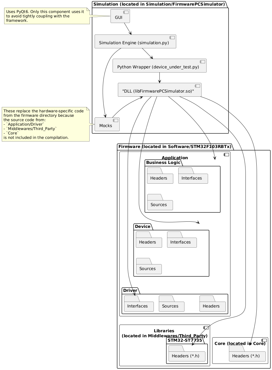
To ensure I don’t forget how it works, I created a small component diagram to visualize the architecture of the simulation. It was done using PlantUML, an open-source UML tool. It’s great because it’s text-based, but one downside I found is that it’s not easy (and sometimes impossible) to organize blocks in an aesthetically pleasing way.
Discussions
Become a Hackaday.io Member
Create an account to leave a comment. Already have an account? Log In.