 Robert Gawron
The new HW version has many minor fixes. Some of them are interesting, so I'll share them in this post.
First, the USB connector used for the power supply ripped off, and I don't have a soldering iron here, so the device doesn’t work. lol. The thing is, micro USB is small, its pads are small (mostly surface-mounted), but the forces when the cable is plugged, unplugged, or moved are huge.
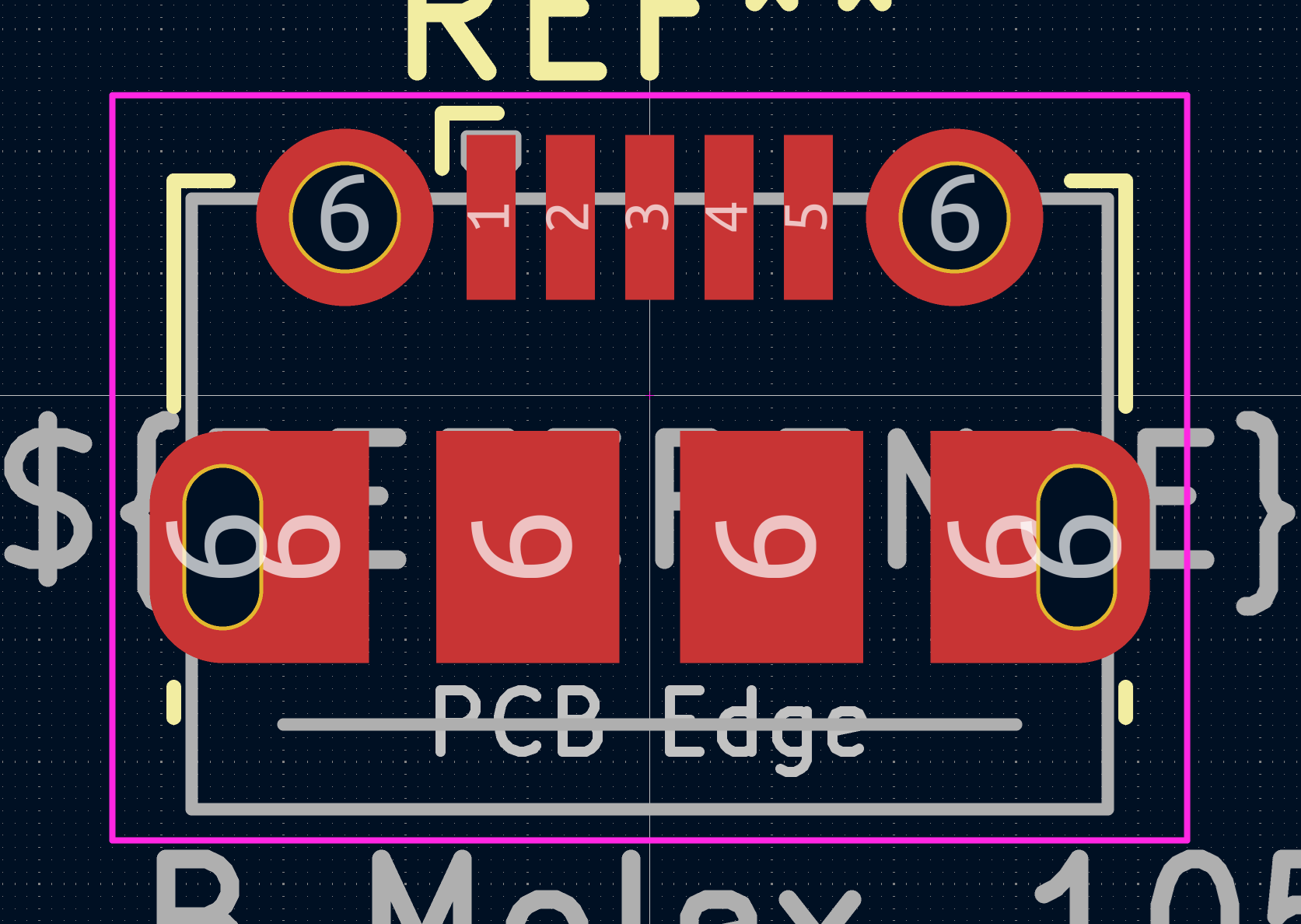
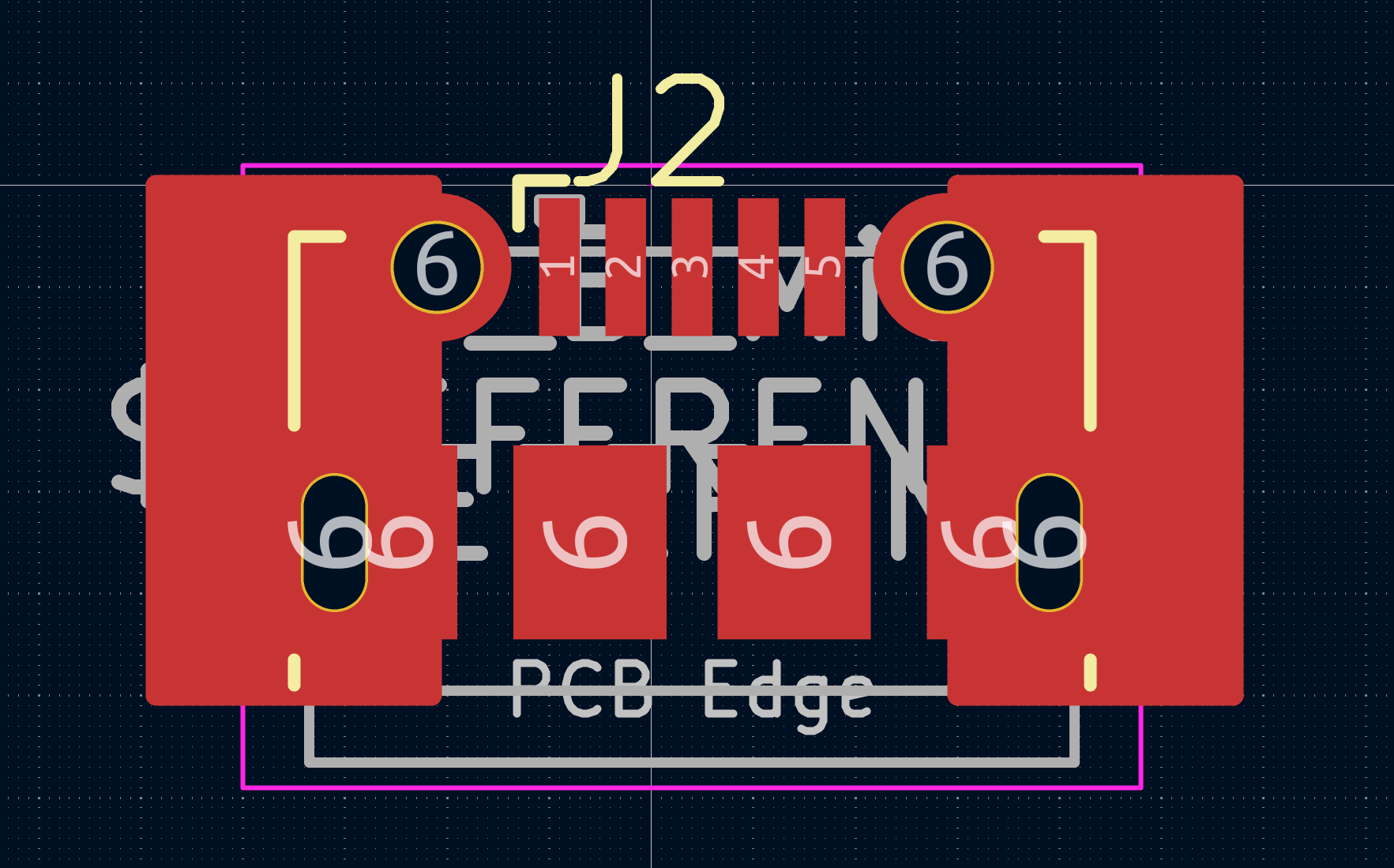
The fix is to make much bigger pads for soldering the shield of the connector, so the mechanical stress is better dissipated. This is shown in the image below (original USB connector from KiCad libraries vs. the new one I made).
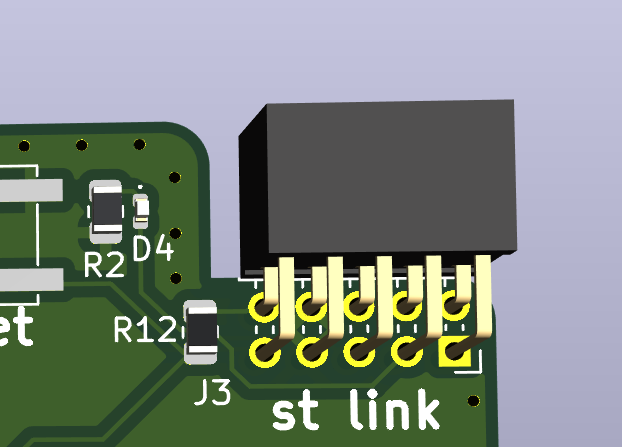
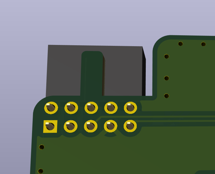
Second, I added a proper STLINK connector to the PCB. In the previous version, I just added a pin header but didn't care which pin was which, so I later had to use wires to connect the device to the programmer. It was annoying and looked lame. BTW, I also added a dent so the STLINK can only be inserted the right way.
The STM chip on the device always uses its own power supply; it's not powered from the STLINK. In case that could be a problem (I don't think so, but who knows-I have a cheap STLINK clone), I added an LED on my PCB between the STLINK's 3V3 and GND. It’s used to simulate the STM’s power consumption and as an indicator that the STLINK is connected.
Third, I switched the ESP. It's no longer an ESP8266 but an ESP32-WROOM-32E. This is because I want to write its code in Rust, and Rust doesn't support the ESP8266 as it's an old chip.
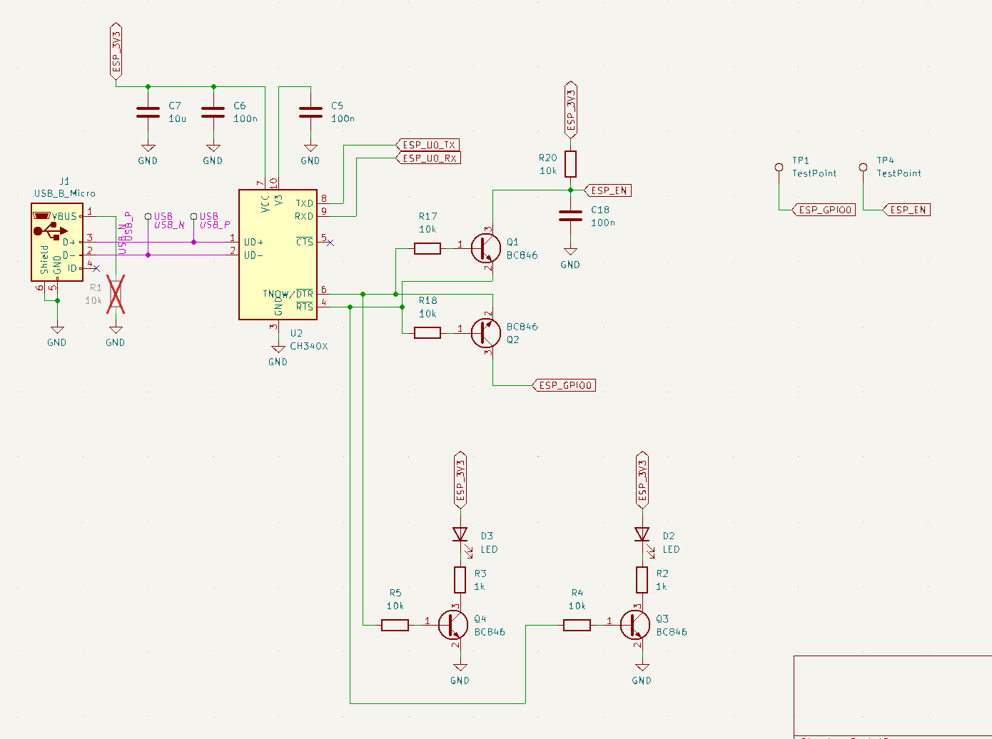
To make flashing the ESP easier (as with the STM, wires are error-prone), I've added on the board a USB programmer for the ESP. It's based on the CH340X, which I find very cool because it's much cheaper than an FTDI chip and easy to get in an easy-to-solder package. An extra feature I added is two LEDs to show the state of RST and GPIO0 - this should be helpful for debugging whether the flashing is working at all.
he circuit is as bellow, it's not tested.
Fourth, all cards are now 1cm shorter while keeping all the previous functionality. I realized all those PCBs next to each other looked so empty - there was so much unused space on the boards.
I also added TVS diodes to ESD-protect the device from whatever is connected via the UART and pulse counter connectors. The diodes are added to all the pins on the SD card as well.
Discussions
Become a Hackaday.io Member
Create an account to leave a comment. Already have an account? Log In.