Close
0%
0%

GNSS module 2.0 - GNSS via Bluetooth

In this project I build a smaller version of my previous GNSS module.
The main features are: LiPo battery, USB, active antenna, bluetooth

Public Chat
Similar projects worth following

This is the second version of my GNSS module which sends NMEA strings via Bluetooth to a mobile device.

The main changes are:

- No antenna reflection backplate, instead of 7x7 cm

- New GNSS patch antenna with > 20 dB gain low noise amplifier

- Smaller battery (18650 is changed to a Lipo 1100 mAh), should still be enough for 12h+ runtime.

- Charging via USB

- Better PCB layout regarding the HF-section (tracks should be the correct impedance now)

- I will try to use NTRIP correction data with a smart phone app

The key featured remain the same:

- GPS, Glonass, Galileo, Baidou support

- 2.5 m accuracy according to datasheet

- Connects old Android devices to a position service

- Low energy consumption

- USB-port for u-center programming and as USB-GPS device

- GPS, Glonass and Galileo configured
KiCAD_global_custom.lib

needed parts, KiCAD lib

lib - 3.63 kB - 08/14/2021 at 07:43

Download

gps-v2.0.7z

KiCAD project

7-Zip - 415.69 kB - 08/11/2021 at 17:25

Download

  • 1 × u-blox NEO M8N GNSS module
  • 1 × HC06 Bluetooth module
  • 1 × Molex 206640 GPS Antenna or Taoglas AGGBP.25B.07.0060A
  • 1 × Serveral SMD 0805 parts listed in the schematics.

  • Assembly

    dechemist11/07/2021 at 20:15 0 comments

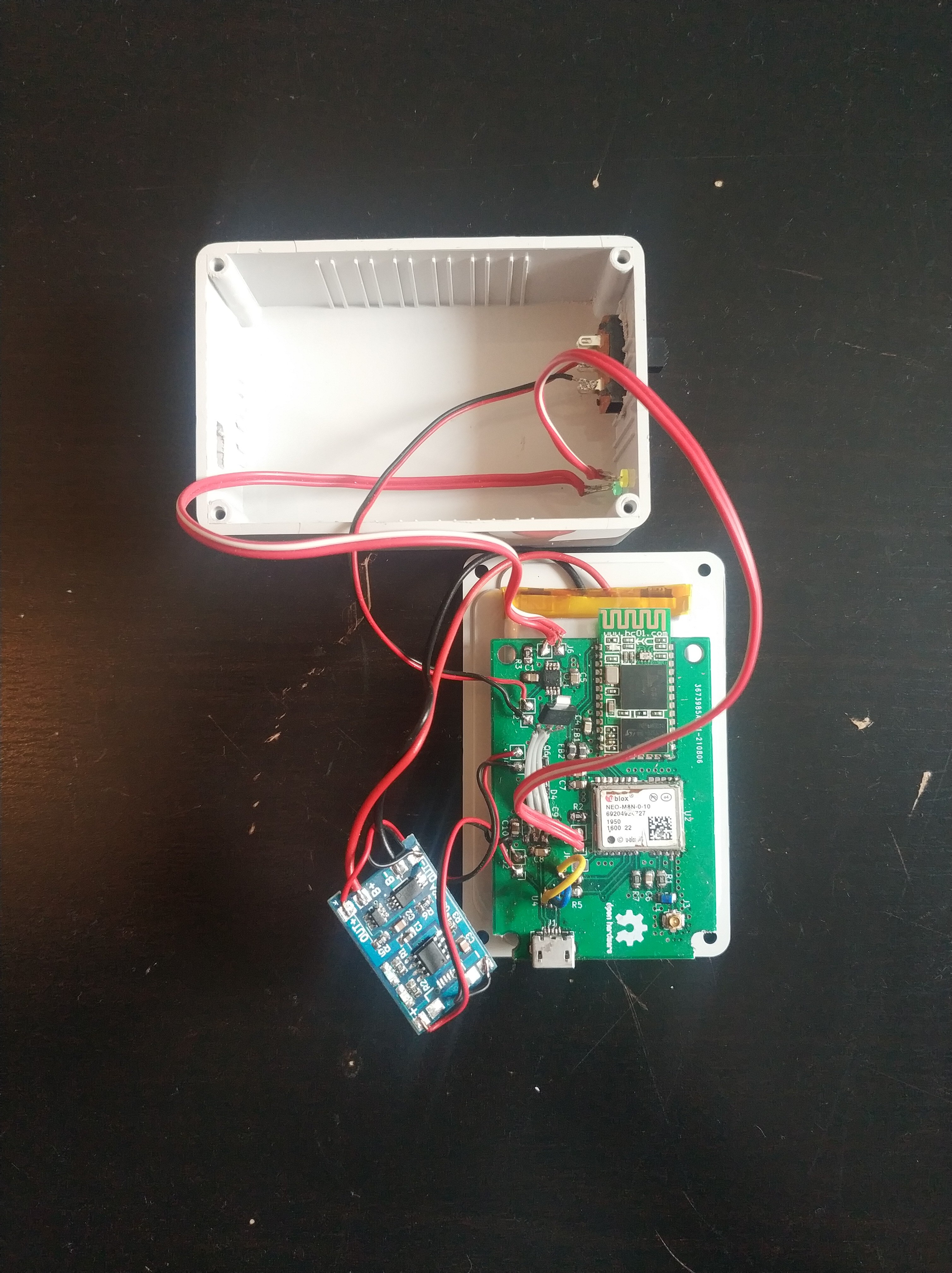
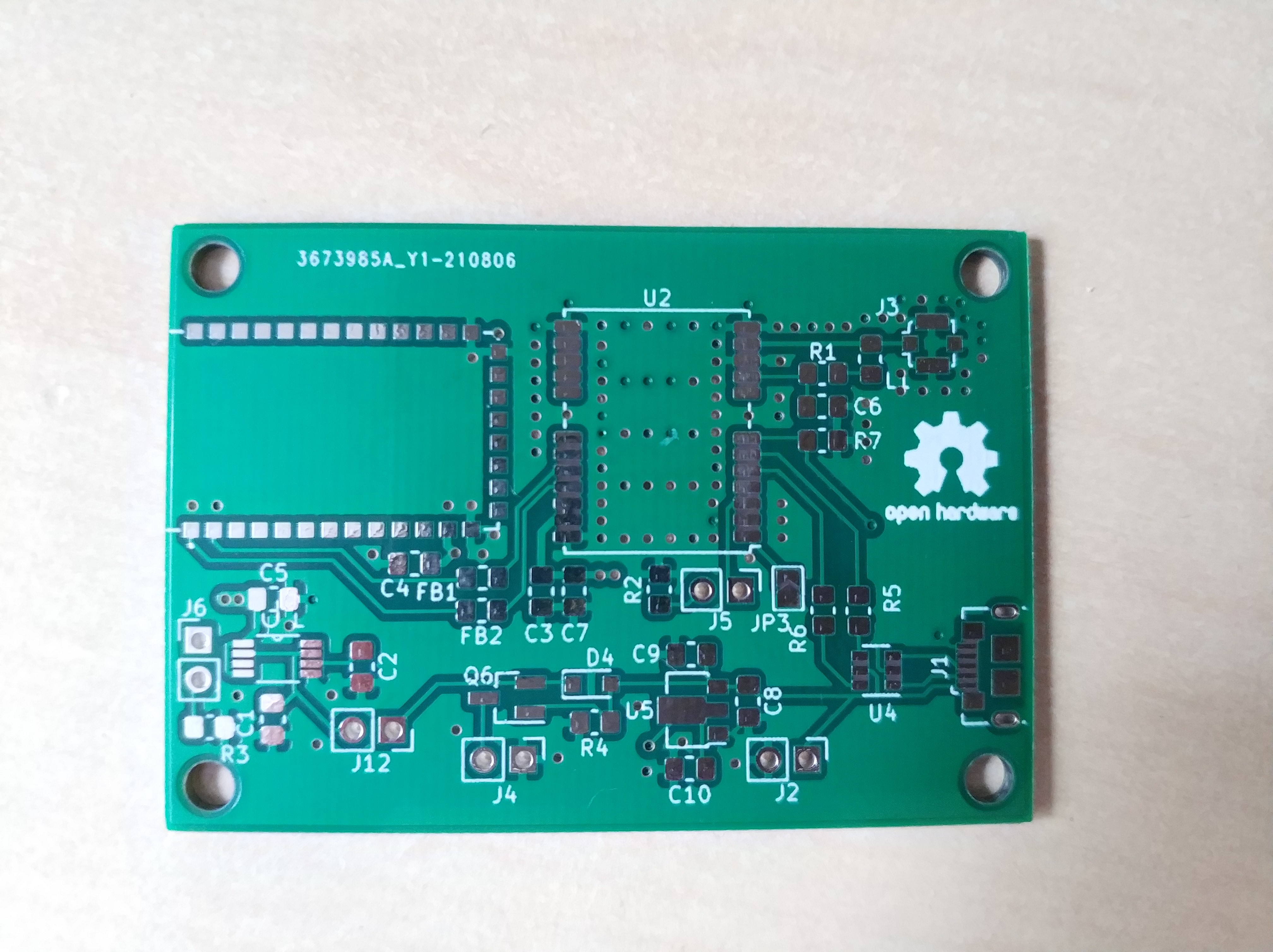
    The build of the module was pretty strait forward...with some complications. Except for one all footprints matched the parts I have. The LDO for VCC_USB was the wrong footprint, a SOT-89-3 should have been a SOT-223. I fixed this by soldering cables to the pads (FYI, this exact mistake was made in the first version of the module).

    I tried to solder the micro USB socket by hand and solder (wire) but could not reach all pins with the soldering iron tip. In the end I cleaned up the pads and used solder paste and a reflow station. To check my connections I connected some wires to a USB-A socket and connected a USB-A to micro USB cable to the module. Thereby I could test the continuance of GND, Vcc, D+, and D- to the PCB through the socket.

    Although the connections were OK, I could not get the PC to recognize the module. Since the connections were definitively OK, I removed the USBLC6 diodes and bridged the contacts of the signal lines. Then a connection could then be established to the module via USB. Once again I have no idea why this is not working although this configuration is recommended in the u-blox NEO8 hardware integration manual. The next design will not have this protection.

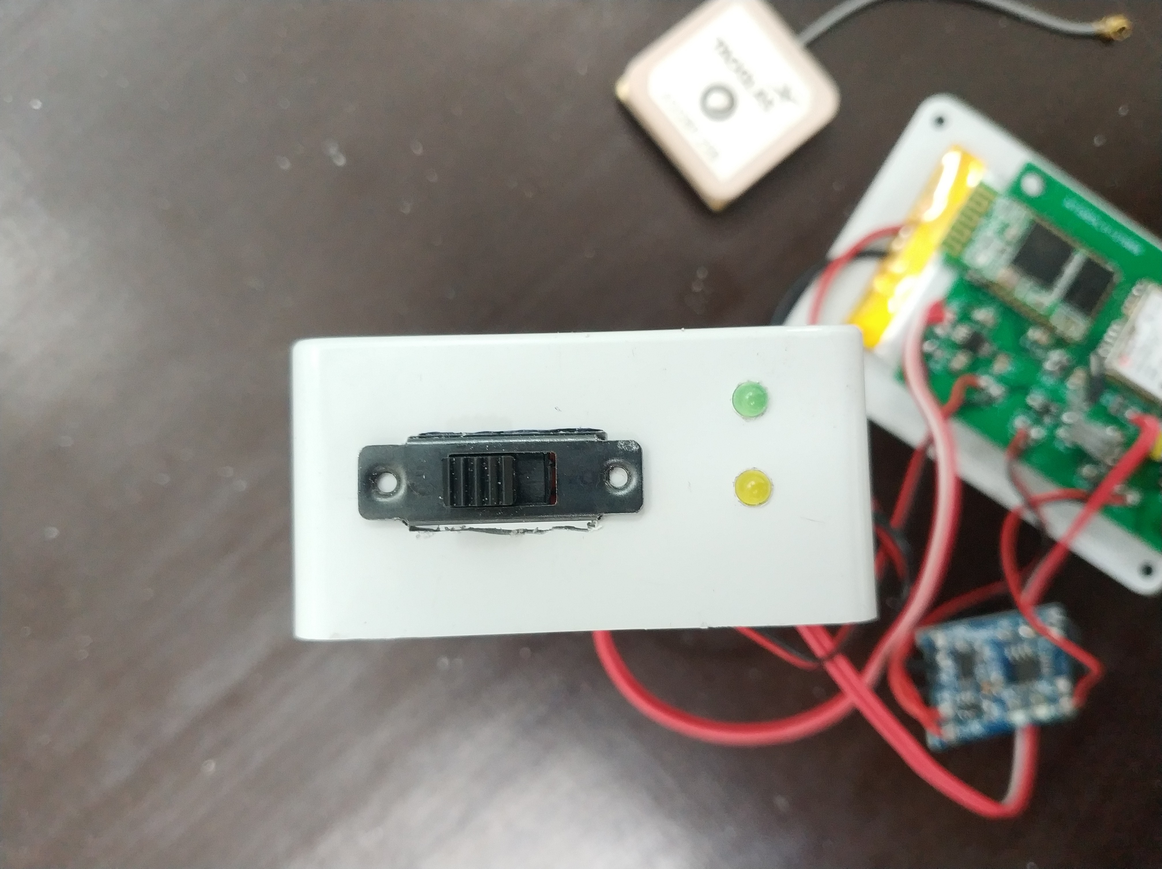
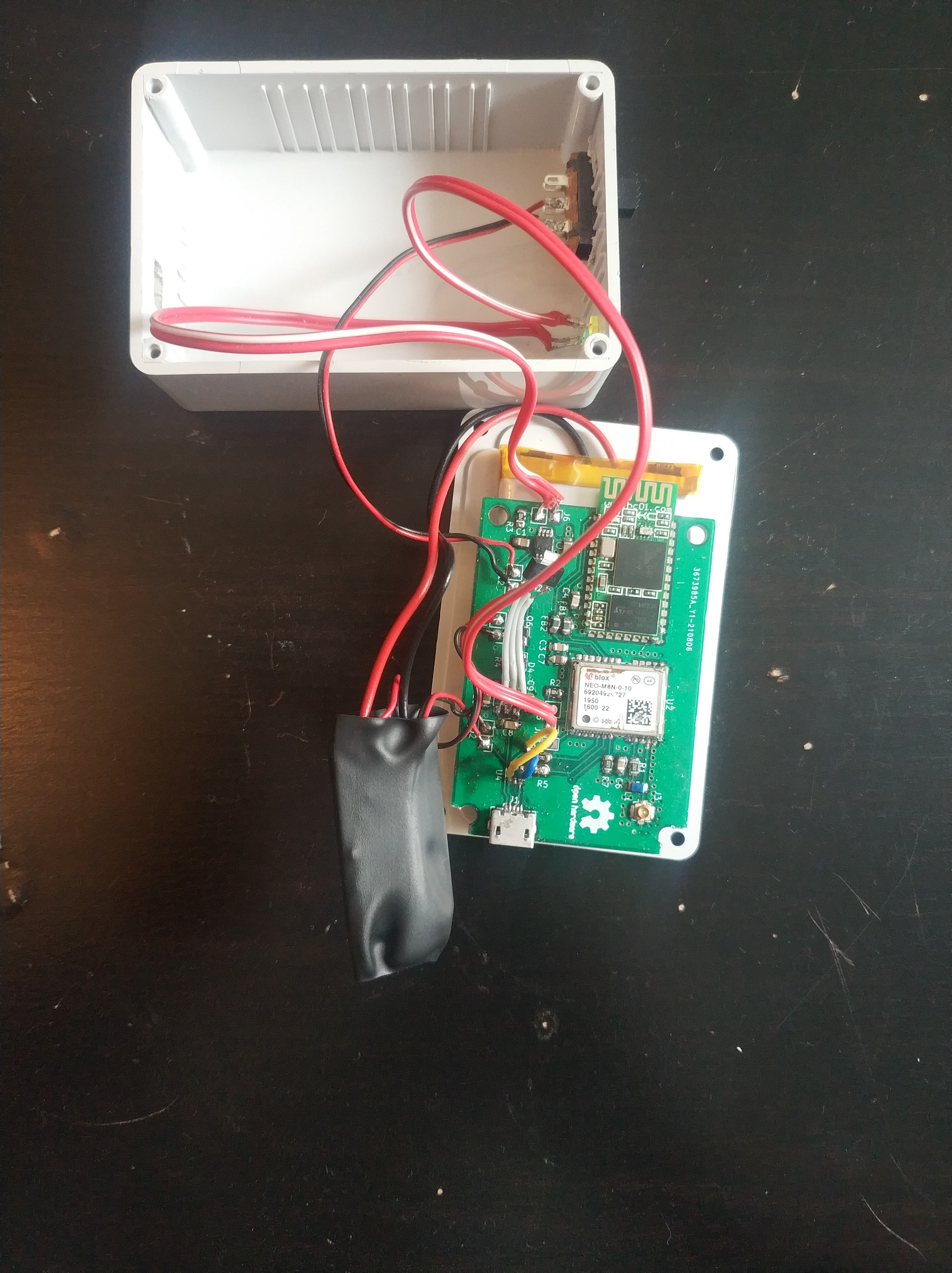
    For the case I used a plastic one this time with outer dimensions of 48x73x23 mm. No more chunky wood box. The USB socket is located on the opposite side than the LEDs and power switch. Most of the internal components are held in place with double sided tape. The battery is taped to the bottom of the box and the PCB is hold on top the battery in the same way. Since the antenna is not that heavy it was also hold in place with double sided tape. The LiPo charger was covered with shrink tubing and stuffed in the box.

  • USB connection problems...fixed

    dechemist09/21/2021 at 18:15 0 comments

    I assembled the board a couple of weeks ago and had some serious problems since with the USB connection. Additionally some private things I had to take care of delayed the search for the cause of the problem.

    In u-blox center the raw messages just arrived sporadically and the config could not be loaded in 'configuration view'. Interestingly with debian the chip was correctly recognized under 'lsusb', in windows however not (device not recognized) WTF?!.

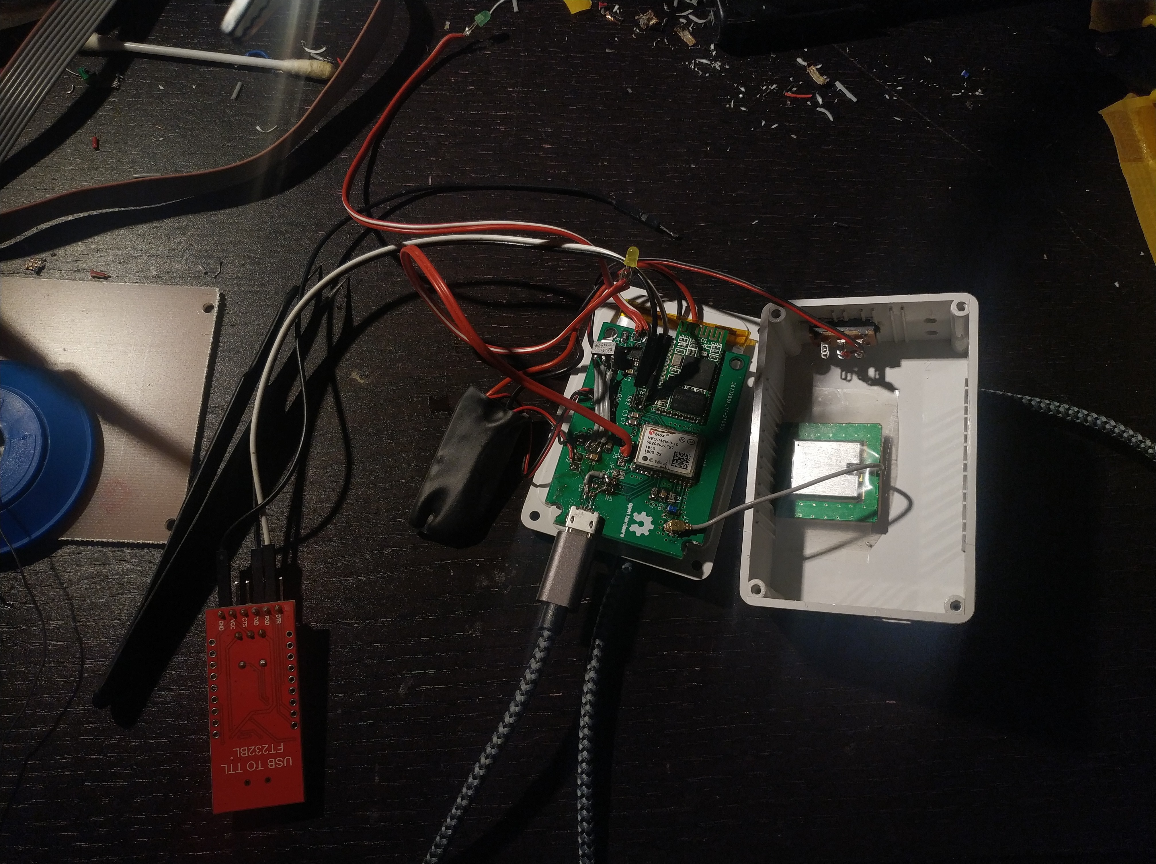
    After some fiddling with a serial2usb converter instead of the bluetooth module I at least could confirm the correct function of the chip! I was sure that I did not destroy it desoldering and putting it on the new PCB.

    [messy bugfixing, a serial2usb converter is soldered in the serial line]

    On the search of the problem I measured the voltages of the voltage converter, USB_Vdd_in and USB_vdd, all seemed fine. After that I checked the signals on the USB data line, they seemed OK.

    Then I remembered a passage from the manual where it states that USB is only activated when Vdd_USB is present (3.3V), so if there is an interruption / instability of this voltage line the USB functionality is activated/deactivated sporadically....like the massages

    I resoldered all capacitors and the voltage regulator for that line and this solved the problem. The chip is now recognized with full USB2 speed without any more problems.


    I already build a case for the device and will upload the pictures and a documentation in a view days.

  • The PCBs arrived...mistakes where made

    dechemist08/23/2021 at 16:33 0 comments

    The PCB arrived and they look perfect, not that I had any doubt when ordering at a big Chinese manufacturer. 

    And of course there are mistakes :/ The voltage regulator for USB power to the GPS chip U5 has the wrong footprint. I used a SOT-89-3 foot print, but the actual part here is way bigger. This can be easily fixed with a few wires, I did the same mistake in my first design and have learned nothing...

    The second mistake is a bit more annoying: The foot print (USB3076-30-A) for the micro USB-B connector does not match the part I have here in my storage (same mistake twice?!). Fortunately the PCB of the Lipo battery charger I am about to use has a similar one on it and I can use this one to make it work even though the very small pins will make fixing this by hand soldering very annoying.

    In the next days I will solder all the parts on, starting with the 3.3 voltage converter.

  • Designing and ordering the PCB

    dechemist08/11/2021 at 18:06 0 comments

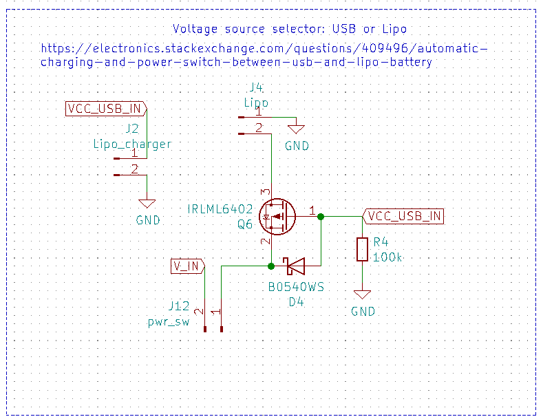
    I designed the PCB in KiCAD with version 1.1 in mind. The main changes here are the power selection circuit. I copied the circuit from a electronics.stackexchange.com post which basically describes a part from a Arduino feather 328p. When USB power is not connected, the LiPo will be used. When the board is powered via USB it closes Q6 and the battery is disconnected.

    Further changes are regarding the proper impedance of the trace to the antenna connector. In the previous version I neglected this completely. The trace was a normal track (0.25 mm) with bends, the impedance (50 Ohms) was properly way off.

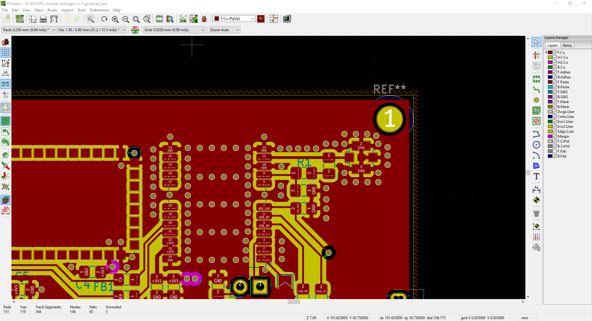
    Using the KiCAD calculator and plugging in the values (h=1.6 mm PCB, f=1.575 GHz) of the track in version 1.1 gives a theoretical optimal track with of 2.9 mm. This is way to wide to fit on the connector. Using the real values of my PCB of h =1.6 mm and 0.25 mm track resulted in an impedance of about 130 Ohm (oh boy...). In this optimized version I took special care to design the HF-section of the board as good as I could (again, I am not an electronic engineer). So I changed the design from 2 to 4 layers with a layer height of 0.2 mm to GND. Entering this in the calculator resulted in a track with of 0.349 mm for 50 Ohms. Furthermore I kept the track straight and used way more vias to isolate the antenna track and connector from any noise. The capacitor in the antenna section was changed from 10 nF (reference design in u-blox manual) to 1 nF according to a friend (electronic engineer) due to the Series Resonant Frequency (?). I hope these changes improve the already very good reception of the module.

    The 4-layer design allowed me to use a Vcc layer for power. An added 10 µF capacitor near the u-blox module should buffer the demand from the chip while searching for satellites. Further smaller changes are the pin headers for the LEDs, LiPO and Lipo-charger as well as way way more vias under the M8N chip.

    I am using the cheap TP4056 Lipo-charger on an external PCB for charging the 1100 mAh Lipo.

    Due to the 4-layers (and the number of vias^^) I send the PCB to a manufacturer in China, the PCBs should arrive with in the next week.

View all 4 project logs

  • 1
    Installing u-blox center on linux

    There is a new version 21 of u-blox center since I used it the last time. I have tried to install it following my own steps but the software crashed every time. So I will use version 20 for my testing on debian 10, which should be fine.

    Installation steps

    - Install wine 6 on debian following this tutorial: https://linoxide.com/install-wine-6-on-debian-10/
    - Install u-center e.g on 'c:\u-center':

    wine u-center_v20.10.exe 

      - Start u-center: wine start /unix ~/.wine/drive_c/u-center2/u-center2.exe

    wine start /unix ~/.wine/drive_c/u-center2/u-center2.exe

     
    Remember to connect and switch on the GNSS module before you start the software. Otherwise the USB-port is not correctly bound in wine. On my computer the chip connects via COM5.

    EDITED

    I just installed u-blox center 21.08 on my windows machine out of curiosity. Apparently you need a u-blox account now for using the software. So its best to ignore this version and use the old one also on windows.

View all instructions

Enjoy this project?

Share

Discussions

Similar Projects

Does this project spark your interest?

Become a member to follow this project and never miss any updates