The build of the module was pretty strait forward...with some complications. Except for one all footprints matched the parts I have. The LDO for VCC_USB was the wrong footprint, a SOT-89-3 should have been a SOT-223. I fixed this by soldering cables to the pads (FYI, this exact mistake was made in the first version of the module).
I tried to solder the micro USB socket by hand and solder (wire) but could not reach all pins with the soldering iron tip. In the end I cleaned up the pads and used solder paste and a reflow station. To check my connections I connected some wires to a USB-A socket and connected a USB-A to micro USB cable to the module. Thereby I could test the continuance of GND, Vcc, D+, and D- to the PCB through the socket.
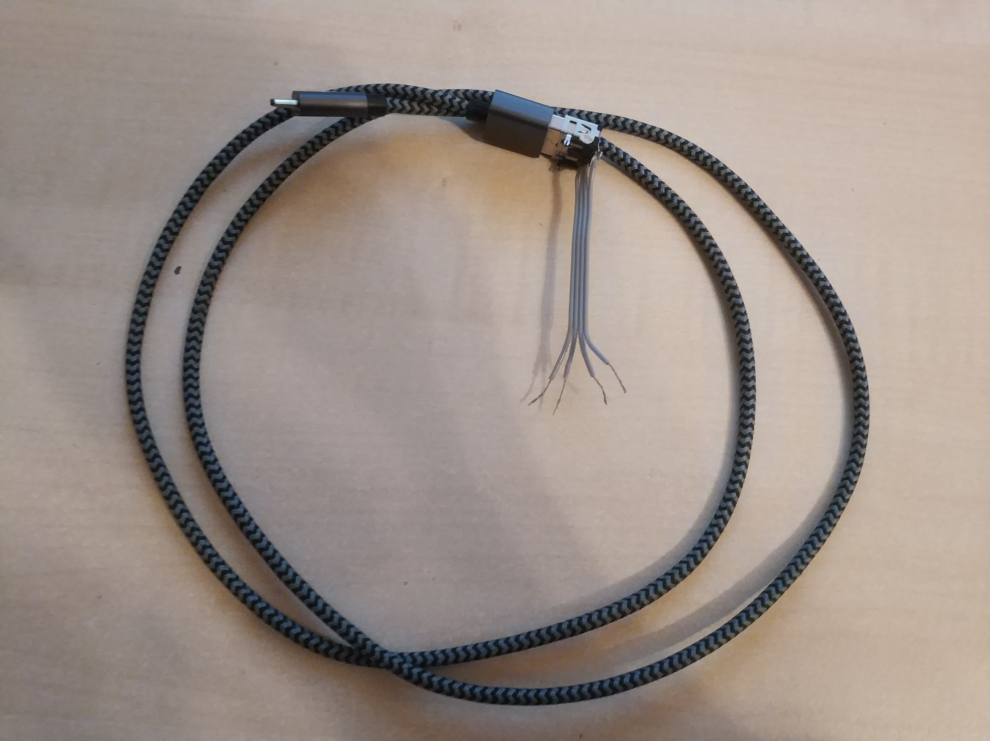
Although the connections were OK, I could not get the PC to recognize the module. Since the connections were definitively OK, I removed the USBLC6 diodes and bridged the contacts of the signal lines. Then a connection could then be established to the module via USB. Once again I have no idea why this is not working although this configuration is recommended in the u-blox NEO8 hardware integration manual. The next design will not have this protection.
For the
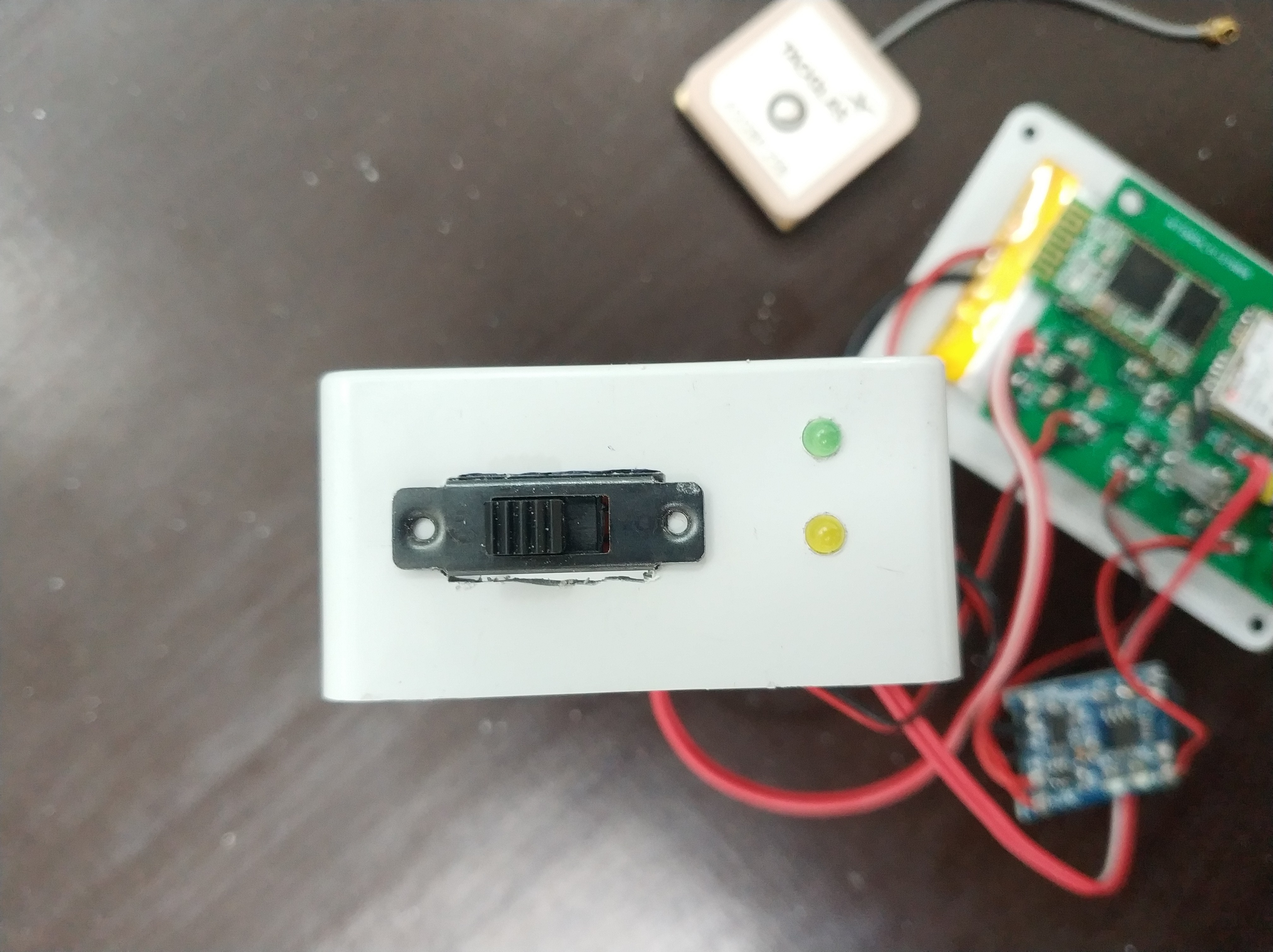
case I used a plastic one this time with outer dimensions of 48x73x23
mm. No more chunky wood box. The USB socket is located on the
opposite side than the LEDs and power switch. Most of the internal
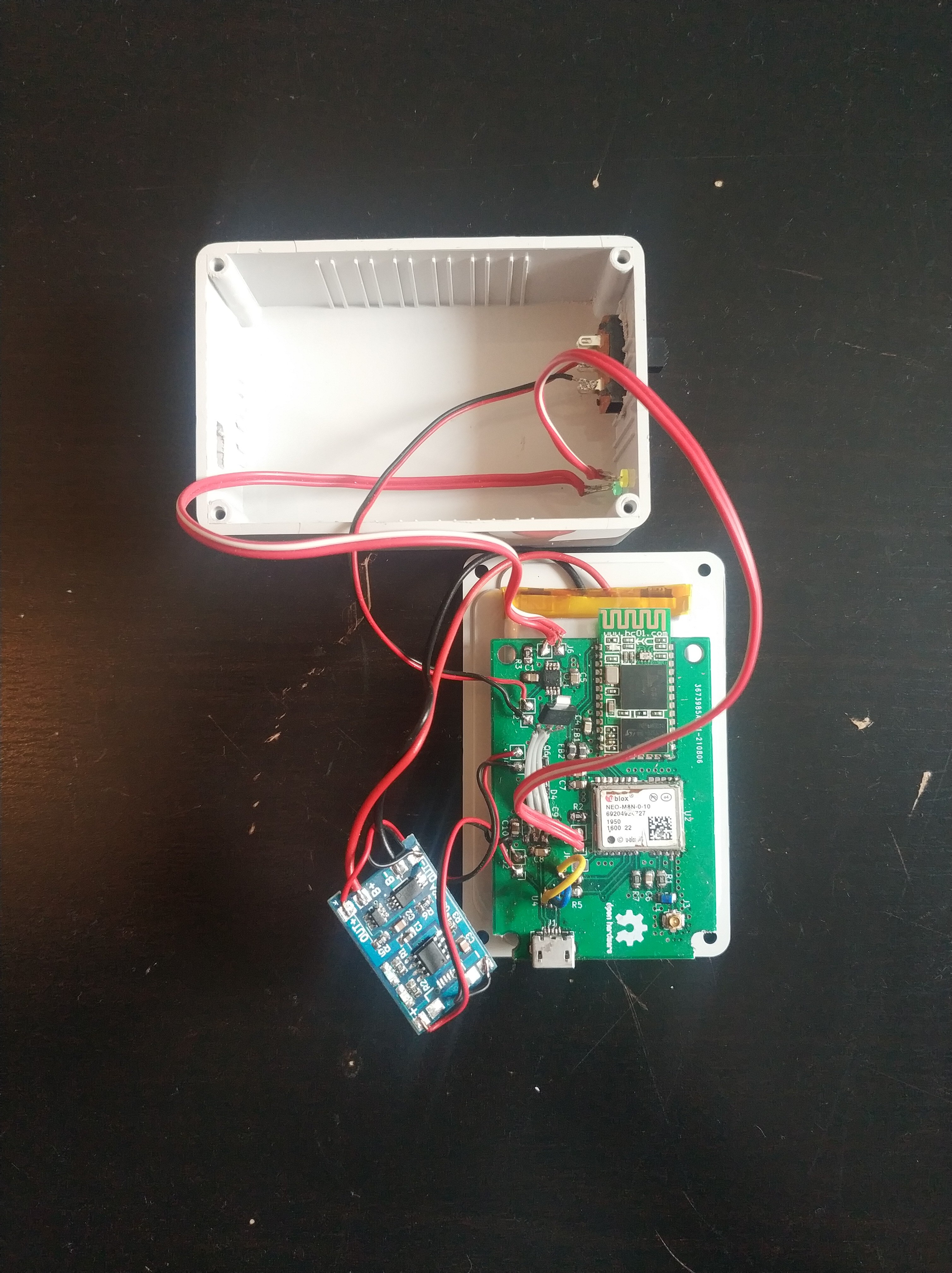
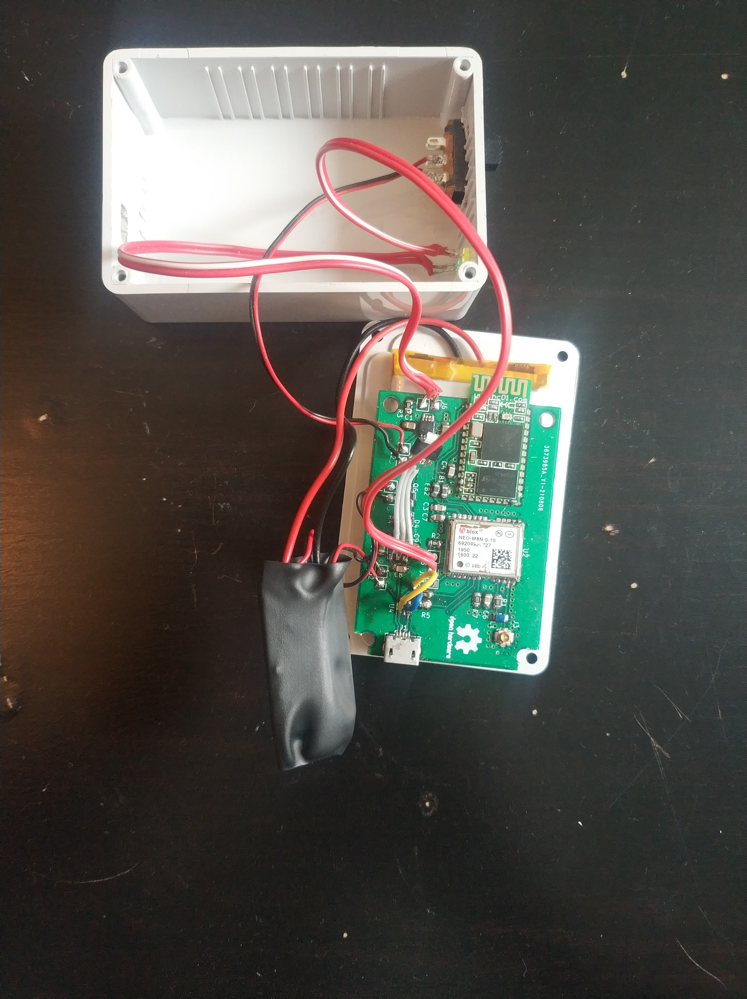
components are held in place with double sided tape. The battery is
taped to the bottom of the box and the PCB is hold on top the battery
in the same way. Since the antenna is not that heavy it was also hold
in place with double sided tape. The LiPo charger was covered with
shrink tubing and stuffed in the box.
Discussions
Become a Hackaday.io Member
Create an account to leave a comment. Already have an account? Log In.