 Ahmed Oyenuga
-
1Step 1
Setting up and Using the Wheel
In order to use the Pick-N-Place Wheel, you'll need to go through the first time setup process, this process involves:
- 3D printing and Assembling the wheel to suite your desired PCB project.
- Generating the required Files for the App.
- Loading and Registering the components into the Wheel's slots.
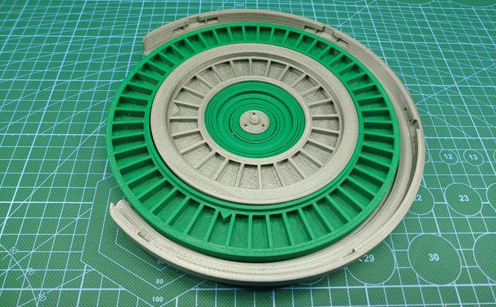
Assembling the Wheel
Step 1: Choose your desired wheel configuration.
Step 2: 3D print the required wheels for your chosen configuration, as well as all the other required parts.
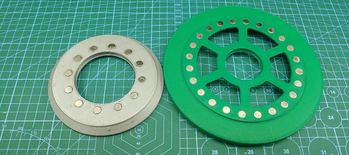
Step 3: install the magnets on the wheels in an alternating pole configuration.
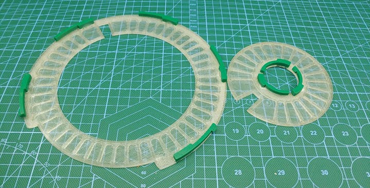
Step 4: Glue on the locking tabs to the transparent top cover for wheel 1 and wheel 2.
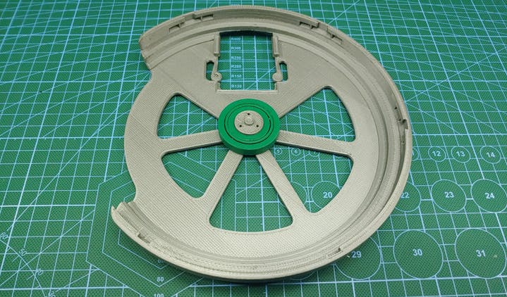
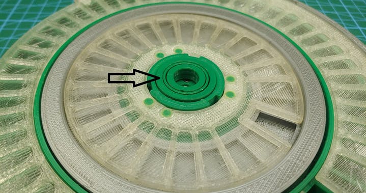
Step 5: Install the 16004 ball bearing, followed by wheel 1.
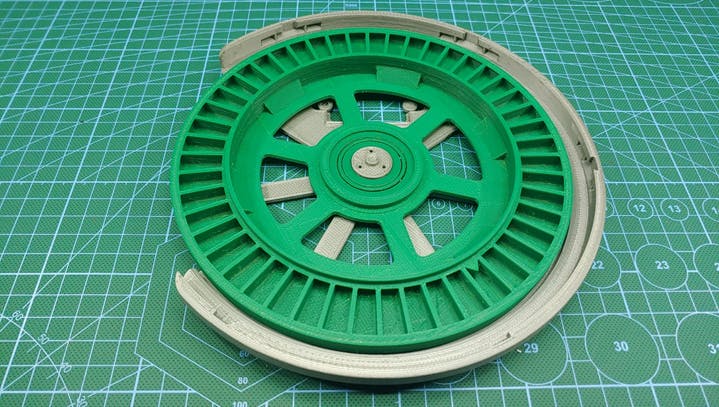
Step 6: Install the 6810 ball bearing to wheel 1, followed by wheel 2.
Step 7: Attach the placing surface bearing holder to the wheel, and secure it with 3 m2 screws.
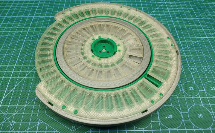
Step 8: Attach the transparent top covers to the wheels, twist clockwise to lock them in the opened state or counterclockwise to lock them in the closed state.
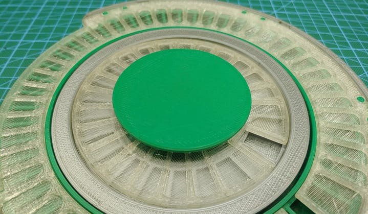
Step 9: Install the 16001 ball bearing, followed by the placing surface.
You may also glue on a mat of some sorts to the placing surface, i use a 1mm silicone mat, this keeps the PCBs from sliding of the placing surface.
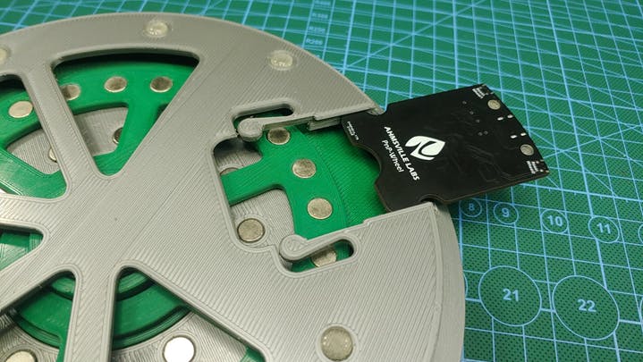
Step 10: Install the Pick-N-Place Wheel board to the base of the wheel, simply push it into its slot until it clicks into place.
Step 10: Attach the rubber base pads.
Congratulations!!! , its a Pick-N-Place Wheel.
Generating the required files
The Pick-N-Place Wheel requires two files to operate:
1. The pick and place csv file for your PCB.
2. A top view Image of the PCB.
Generating the pick and place csv file
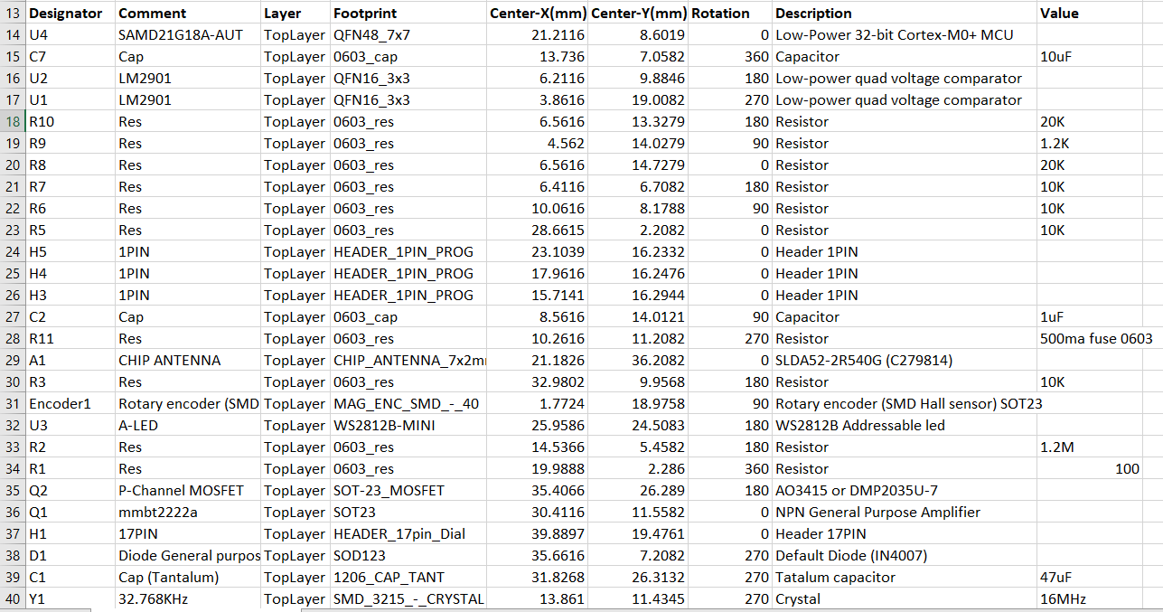
For every PCB you design, there is an associated pick and place file that can be generated, this can be done from the PCB design software. This pick and place file must be a dot(.) separated .csv file and it should contain the following columns:
1. Component Name
2. Component Value
3. Component Footprint
4. Component Designator
5. Component Layer
6. X-position (board origin at the bottom left corner)
7. Y-position (board origin at the bottom left corner)
![]()
A typical pick and place csv will look like this. Generating the Board Image.
Like the pick and place file, most PCB design software will give you a 3d view of your board design, from which an image can be extracted, the image doesn’t have to come from the 3d view though, any image that gives you a good enough sense of where components are placed on the board will suffice.
Your PCB should have its origin at the bottom left corner of the board, and the generated image needs to be in the same aspect ratio as your board, for example, if your board size is 20mm by 40mm the image size can be 10px by 20px, 50px by 100px or 2000px by 4000px, all this sizes are acceptable because they have the same aspect ratio as the board size, so a 100px by 500px image will not work for the 20mm by 40mm board.
The image also needs to be cropped to the edges of the board as shown in the sample image bellow.
If your PCB has components on the bottom side, make sure to also generate an image for the bottom side of your board.
Preparing the Generated Files
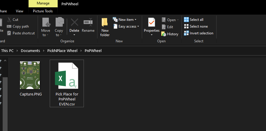
After generating the .csv file and the board image, you’ll need to copy both files into a new folder, this will be the working folder that will be used by the Pick-N-Place Wheel App for the specific PCB project, the folder should contain only one csv and one image, for a PCB that only has components on the top side, one csv and two images for a PCB with components on the top and bottom sides.
![]()
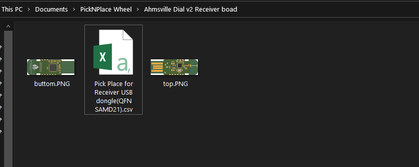
Sample folder for a traditional PCB with components on the top side only ![]()
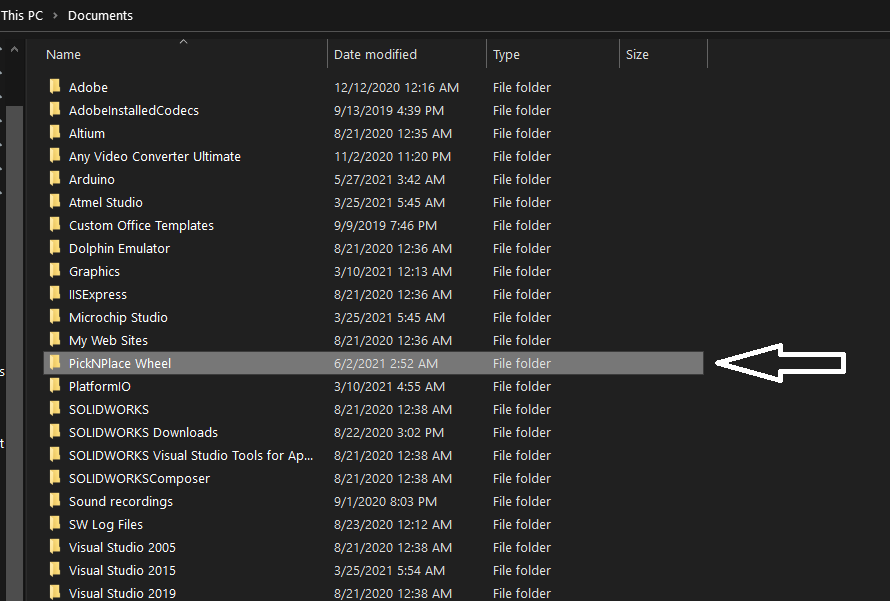
Sample folder for a PCB with components on both sides The folder containing the csv and image should then be copied into the “PickNPlace Wheel” folder which can be found inside the Documents folder, this folder is automatically created when you download and install the App from the github repository, the folder should hold all of your pick and place PCB projects, if you don’t see this folder in your documents folder, launch the App and then close it, the folder should show up.
![]()
Using the App for The First Time
Once all the required files have been copied to their appropriate folders, the next step is setting up the wheel and the app for your first board assembly.
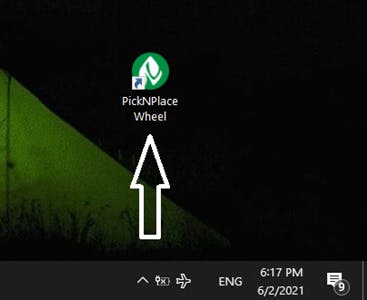
First your going to want to launch the application.
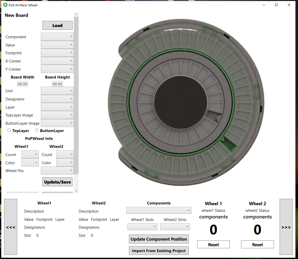
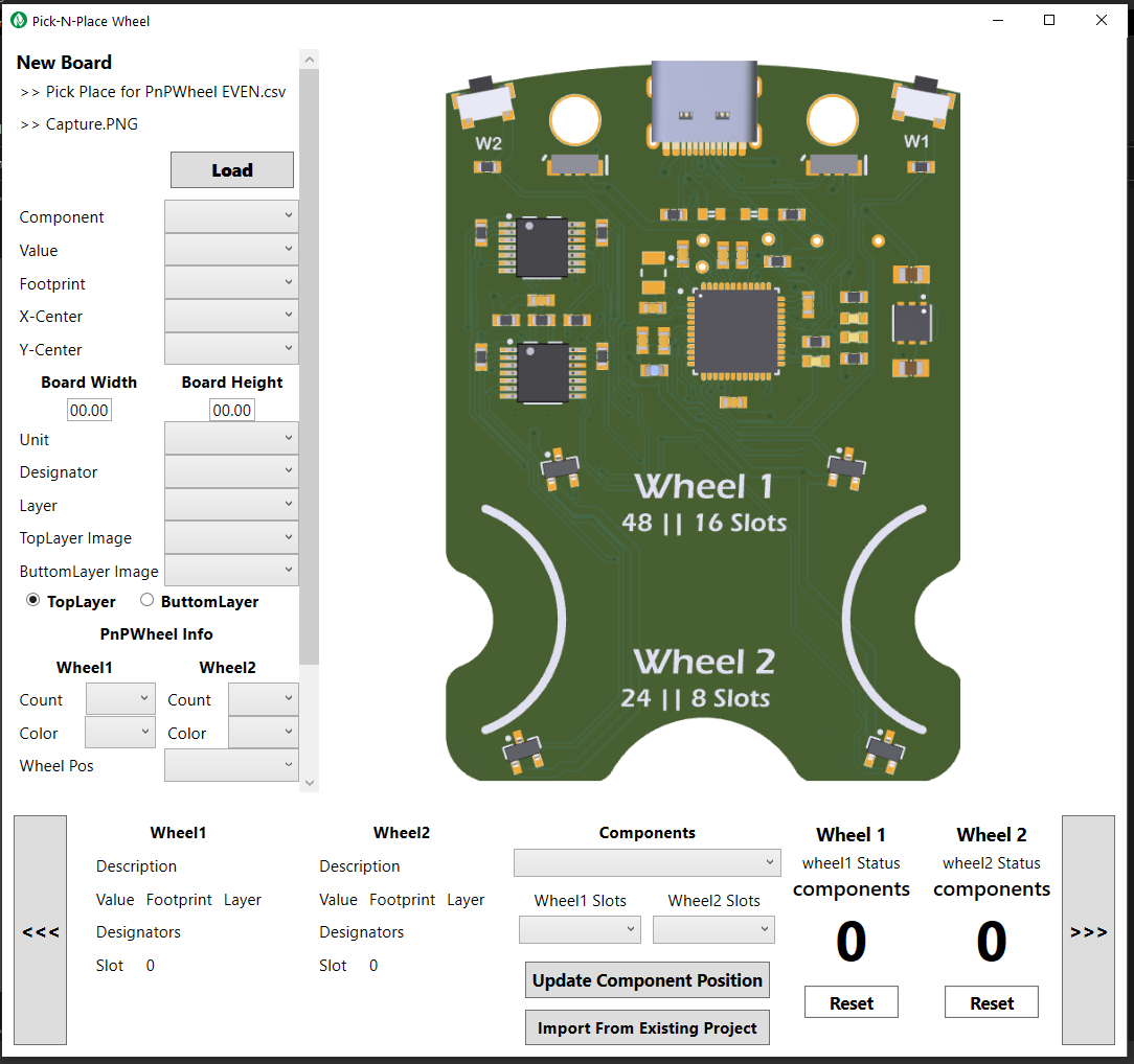
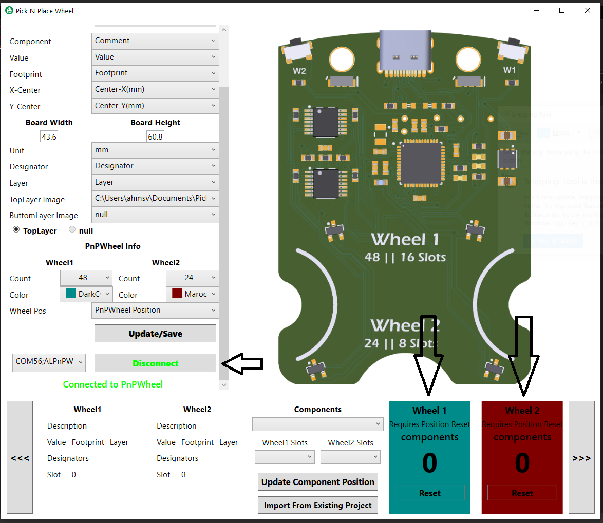
![]()
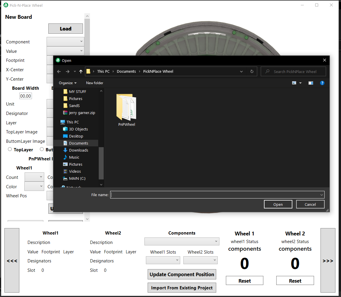
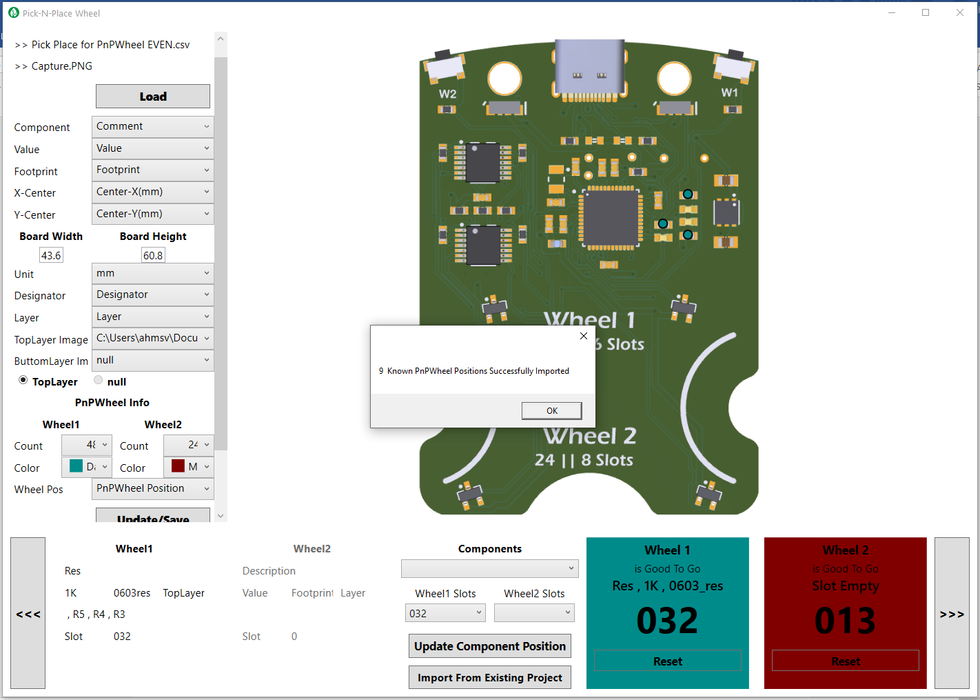
The Pick-N-Place Wheel Application interface Once the app opens up, click on the Load button, this will open up a dialog box, asking you to choose a project file.
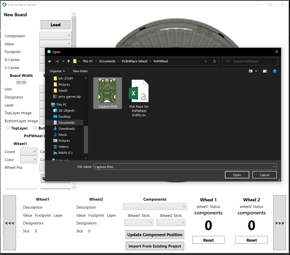
Navigate to the folder containing the csv and image and select any of them.
![]()
![]()
After selecting the file, you will notice the image on the app change to the picture of your board, indicating that the required files have being successfully loaded.
You’ll also notice that the file names are listed on the top right corner of the app.
![]()
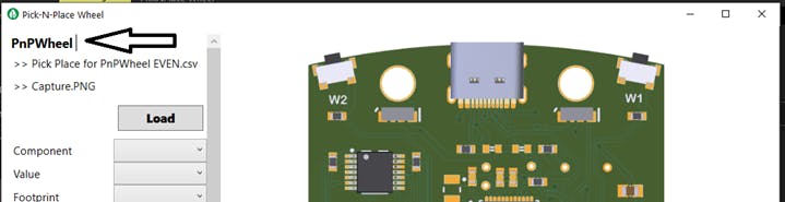
You can name the project (optional), by simply double clicking on New Board, and then typing in your desired project name.
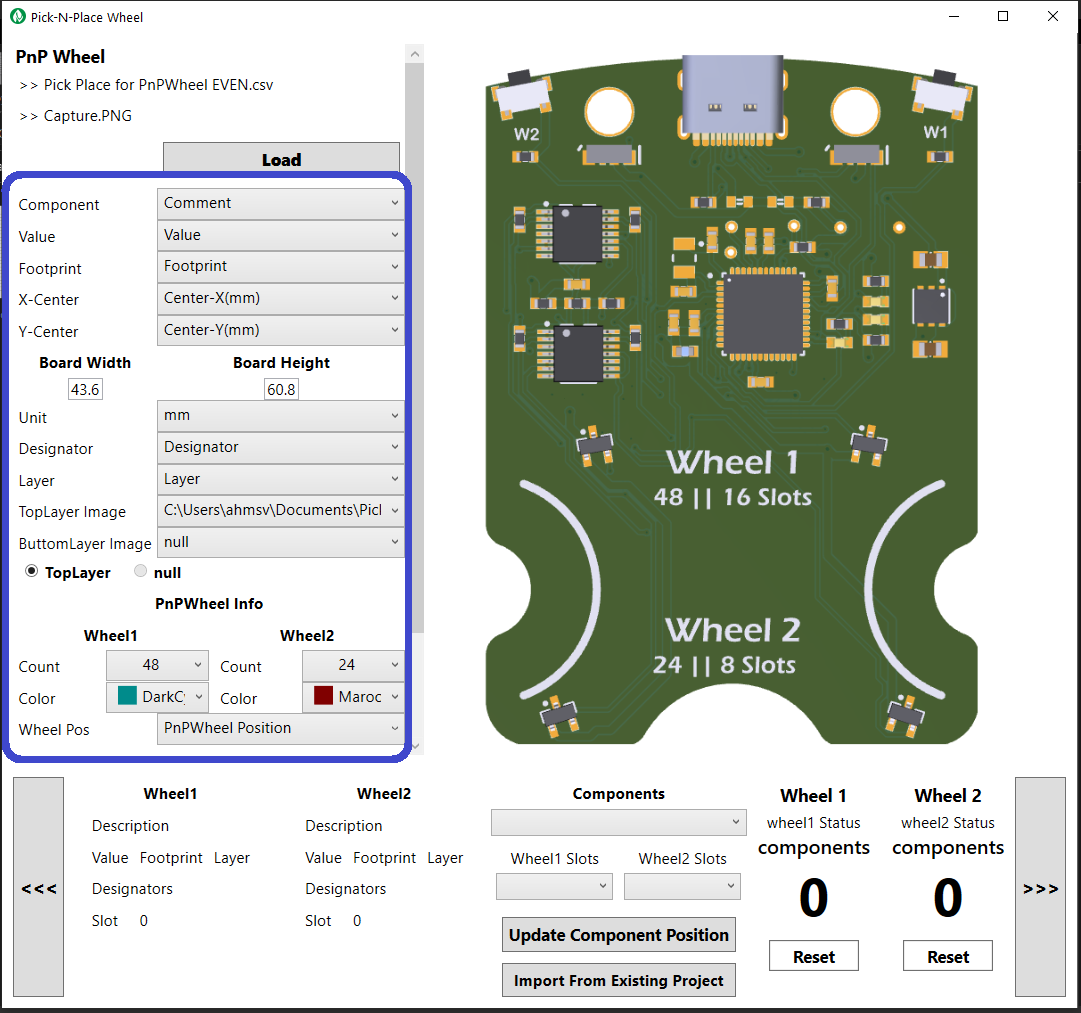
The next step is setting the columns from your csv file to their appropriate comboboxes in the app.
1. Component box should be set to the column that has the names of the components.
2. Value box should be set to the column that has the values of the components.
3. Footprint box should be set to the column that has the footprints of the components.
4. X-Center box should be set to the column that has the x position of the component.
5. Y-Center box should be set to the column that has the y position of the component.
6. The board width and height should be set to the width and height of the PCB (the PCB design software will tell you this values).
7. The unit should also be set accordingly
8. Designator box should be set to the column that has the designators of the components.
9. Layer box should be set to the column that has the layer of the components.
10. TopLayer image should be set to the location of your generated board Image.
11. BottomLayerimage should be set to the location of the generated Image for the bottom layer of your board (set to null if your board does not have components on the bottom layer).
Under PnP wheel info, your going to want to set the slot count for your specific Pick-N-Place Wheel, so if you assembled your wheel with 48 slots for wheel1(bigger wheel) and 24 slots for wheel2(smaller wheel), you should set wheel 1 count to 48 and wheel 2 count to 24. All combinations are supported, so you could have wheel1 = 48 slots & wheel2 = 8 slots, wheel1 = 16 slots & wheel2 = 24 slots or wheel1 = 16 slots & wheel2 = 8 slots. Just make sure you set the slot counts in the app accordingly.
You should also set distinct color identifiers for the wheels, this makes it easy to tell which wheel the displayed information is coming from.
The last box named Wheel pos should be set to PnPWheel Position.
![]()
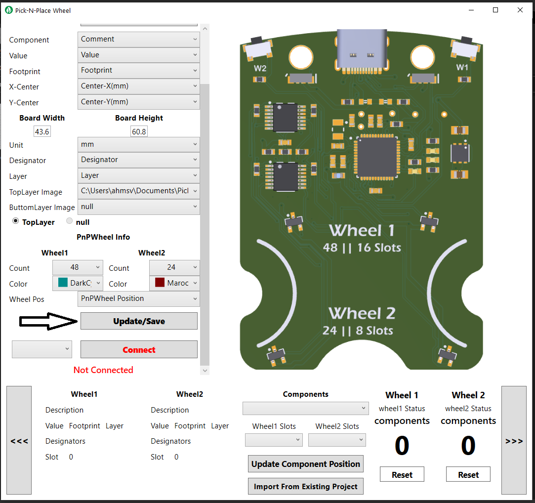
After completing the selections, click on Update/Save button, this will allow you to save all your selections into a text file, so that the next time you load the project, all your selections are remembered. You should also remember to always save after making any modifications to the selections.
![]()
Loading Components into The Wheel Slots
After the initial setup process described above, the final step before you can start populating your PCB is Loading components into the wheel and updating the pick and place csv with the corresponding slot indexes, this is a very straight forward process, and it only need to be done Once.
There are two ways to load the components and their slot indexes:
1. Physical Loading Process – if you are using the wheel for the very first time, you will need to go through the steps described below for the physical loading process, this process allows you to fill the wheel with the components required for your board while also allowing you to update the positions (slot indexes) that specific components are loaded into.
2. Import Loading Process – if you have already done the physical loading process once and you have already setup the Pick-N-Place Wheel for a different PCB and you’ll like to use the same wheel to populate a new PCB, probably because the boards use the same sets of components. In that case you don’t have to make a different Pick-N-Place Wheel, you can simply import the “components position information” form the csv for the previous PCB. What this essentially means is that if your PCB projects often use the same sets of components, you can use one Pick-N-Place Wheel to assemble them all.
Physical Loading Process
First, you’re going to want to connect your Pick-N-Place Wheel to your computer via a USB cable, after which you can then click on the connect button on the app. On successful connection, you’ll notice the status box for wheel 1 and wheel 2 blinking, indicating that your wheels “require position reset”.
![]()
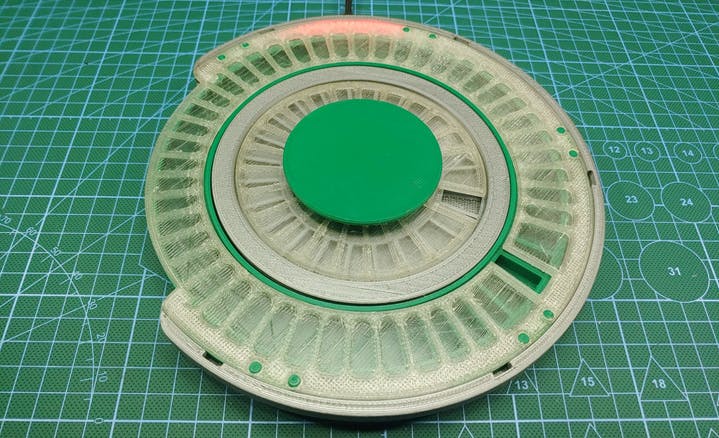
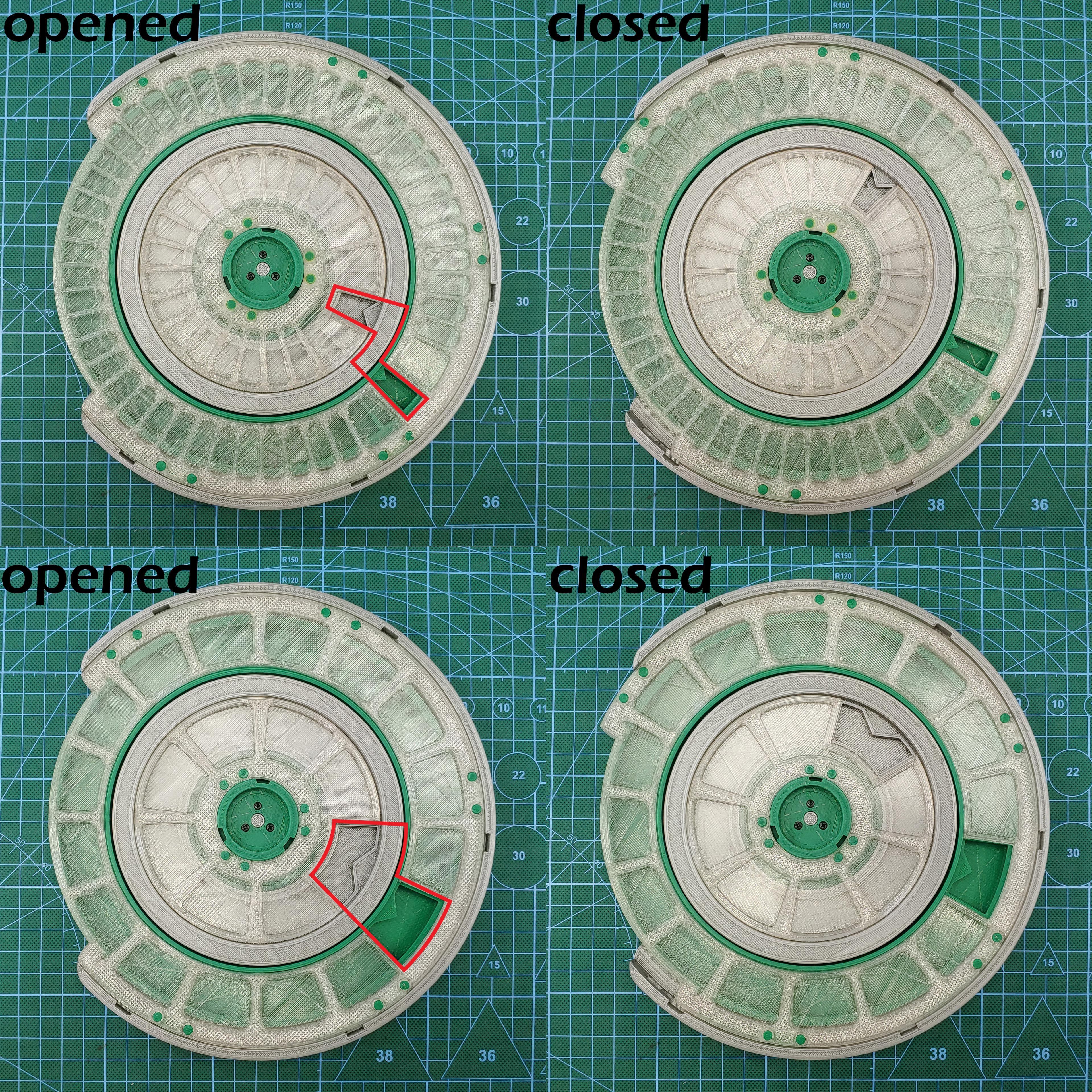
Before resetting the wheel, make sure the top covers and their slot openings are in the opened state, resetting the wheel in the closed state will produce erroneous indexing. The images below shows the wheels in their respective opened and closed states.
![]()
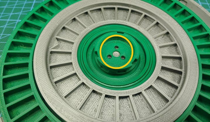
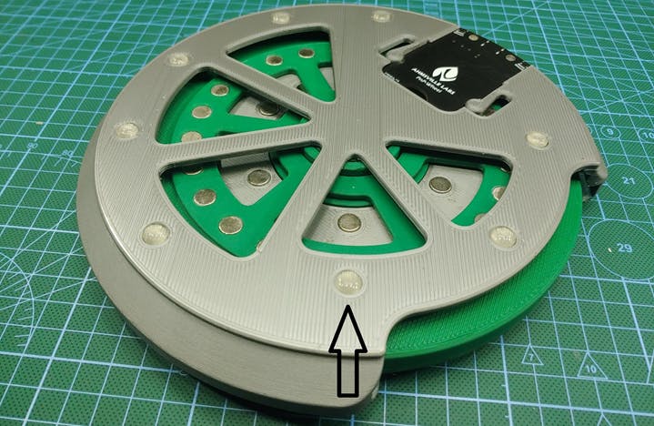
To reset the wheels to the start position (slot index 1), simply rotate both wheels until the slot with an arrow head is exposed, once the wheels are in the start positions, click on the Reset button for both wheel 1 and wheel 2, this will set the wheel positions in the Pick-N-Place Wheel to “1” and the status box should also stop blinking.
After the reset process, you’ll notice that the wheel index updates on the app as you rotate the wheels.
Its also a good idea to double check that the start positions on the wheel is set properly, by simply rotating the wheels around the slot with the arrow head, the index of this slot on the app should always be “1”. The leds on the wheel will also shine blue whenever this slot comes around.
![]()
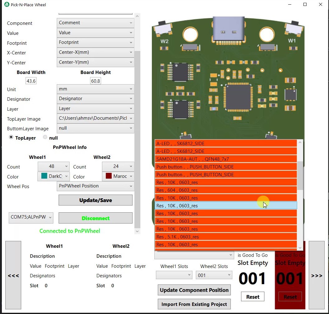
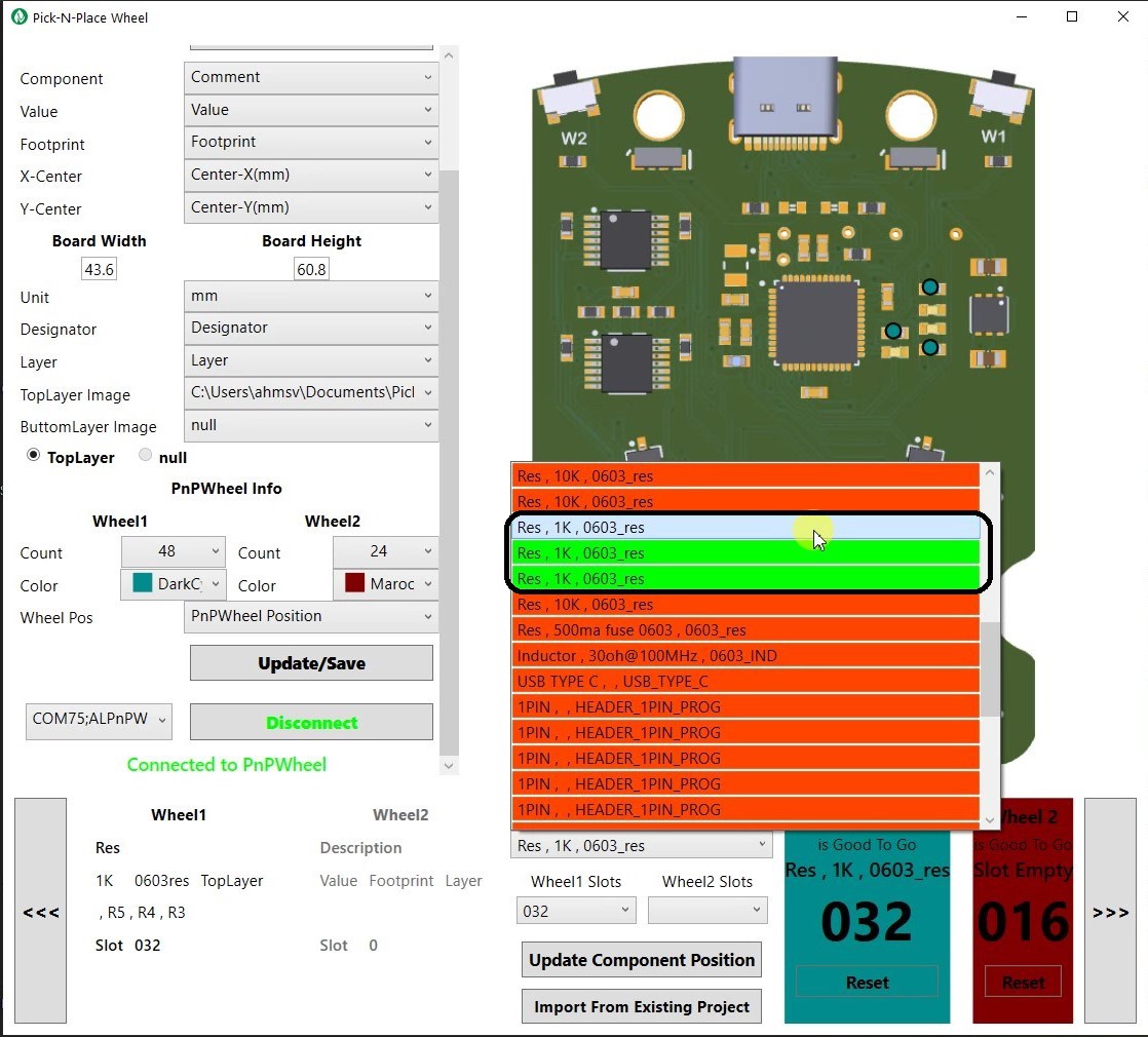
At this point you may now begin loading components into the slots.
Under the Components dropdown, you’ll find the list of all components that needs to be loaded for your PCB, the items in the list are highlighted in OrangeRed to indicate that the components don’t currently have a valid index in your wheel.
![]()
Steps to Loading Components into the Pick-N-Place Wheel:
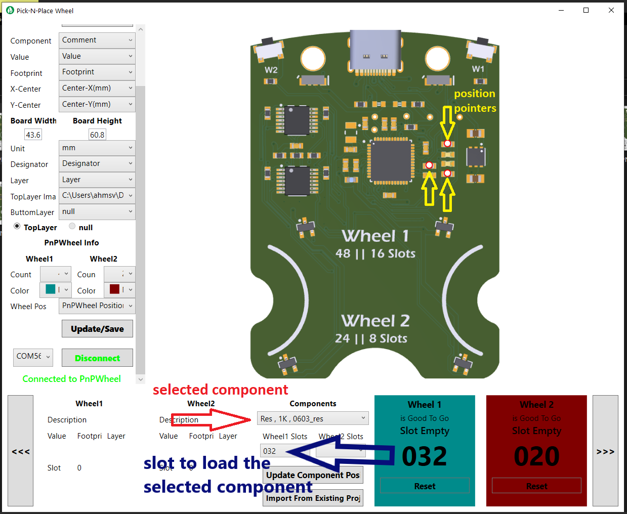
1. Select a component from the Components dropdown, on selection, you’ll notice pointers on the board image indicating the positions on the board where the component is supposed to be placed.
![]()
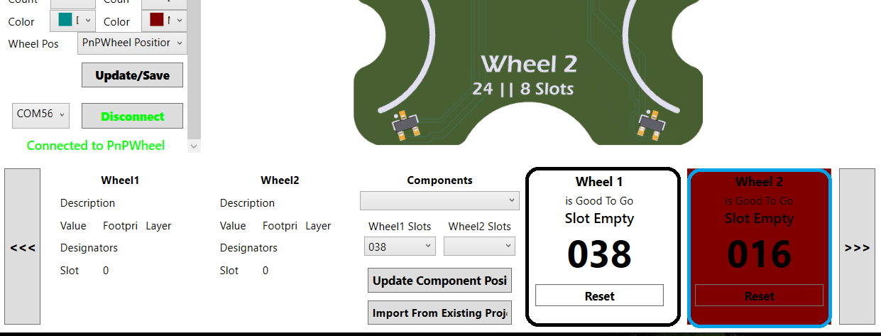
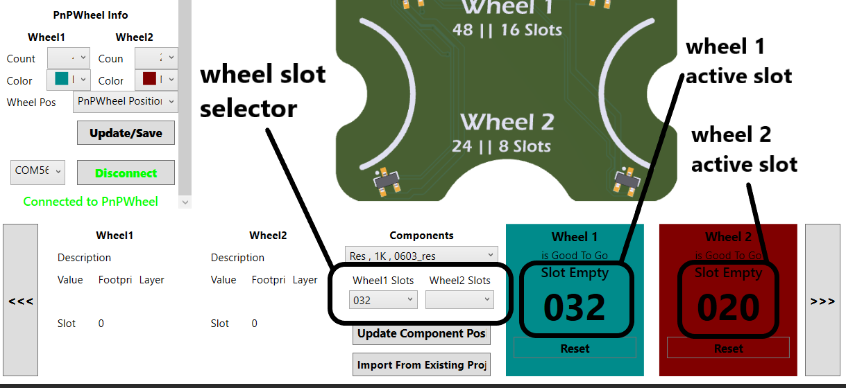
2. Rotate the wheel to any free slot (wheel 1 or 2), make sure the slot number shown in the wheel slot selector matches the corresponding slot number shown in the status box.
![]()
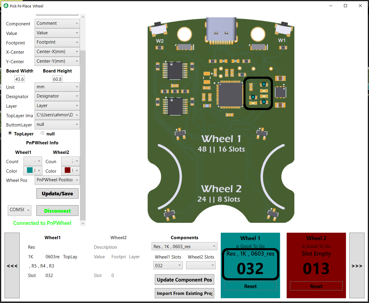
3. Load the component into the appropriate slot with the help of the 3d printed funnel. For the example shown above, 1k 0603 resistors will be loaded into slot 32 of wheel 1.
4. After loading the component into the wheel, click on “update component position” to register the position of the loaded component. If you then go under Components again, you’ll notice that every instance of the newly loaded component has changed to green, you’ll also notice that whenever you rotate the wheel to the slot where the component is loaded, the component details are shown in the appropriate wheel status box and the pointers on the board should also take on the color of the appropriate wheel.
![]()
![]()
5. Repeat steps 1 - 4 for all the other components required by your PCB.
Import Loading Process
To load component positions from an existing project’s pick and place file, simply click on the “import form existing project” button and then locate and select the csv file that you’ll like to import the position information from.
![]()
After the import process, you’ll notice that the components with known slot indexes will be updated and those components will be highlighted in green under the components list.
After any of the two-loading process described above has been completed, you are now fully setup to populate your first PCB with the Pick-N-Place Wheel.
Organizing your Pick-N-Place Wheel Projects
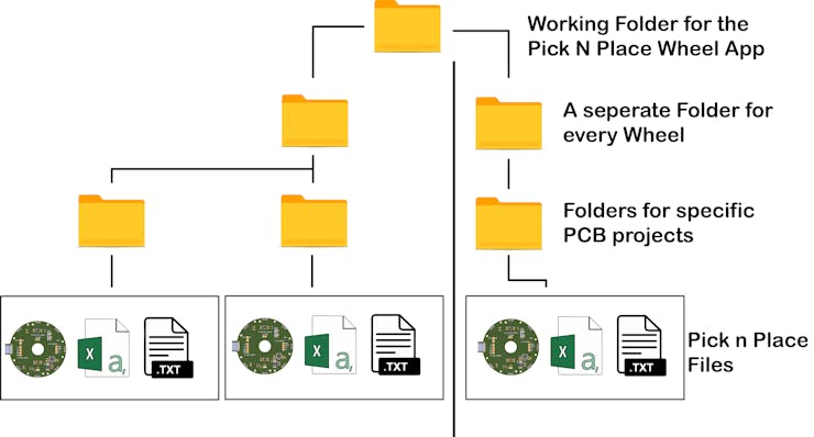
If you assemble a lot of PCBs, you’ll most likely want to build more than one Pick-N-Place Wheel, so it’s really important to properly organize all the files used by the App.
The image above shows the recommended way to organize the generated files, at the top level you have the main working folder for the App, this is where the App will first direct you to when you click on the Loadbutton, on the second level you have a folder for every Pick-N-Place Wheel that you build, its important to create a separate folder for every wheel since you’ll likely be loading the wheels with different sets of components. On the third level you have the main PCB project folders, this is where you’ll put the generated csv file and the board image, this folder should also hold the config.txt file for the specific PCB project, a new folder must be created for every board that you intend to populate using the Pick-N-Place Wheel.
Final Notes:
- The Pick-N-Place Wheel requires a 3D printer with at least a 220 x 220mm Bed size.
- The Pick-N-Place Wheel App is currently only supported on Windows PCs, but a web version is currently in development, so it will eventually be accessible on any operating system.
Pick-N-Place Wheel
The Pick-N-Place Wheel is a complete solution for manual PCB assembly, component indexing and storage.


Discussions
Become a Hackaday.io Member
Create an account to leave a comment. Already have an account? Log In.