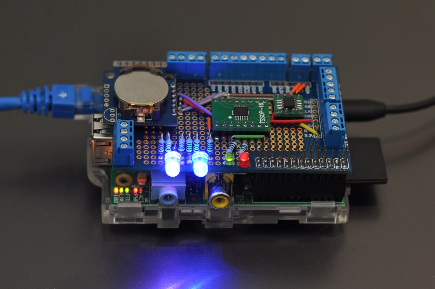
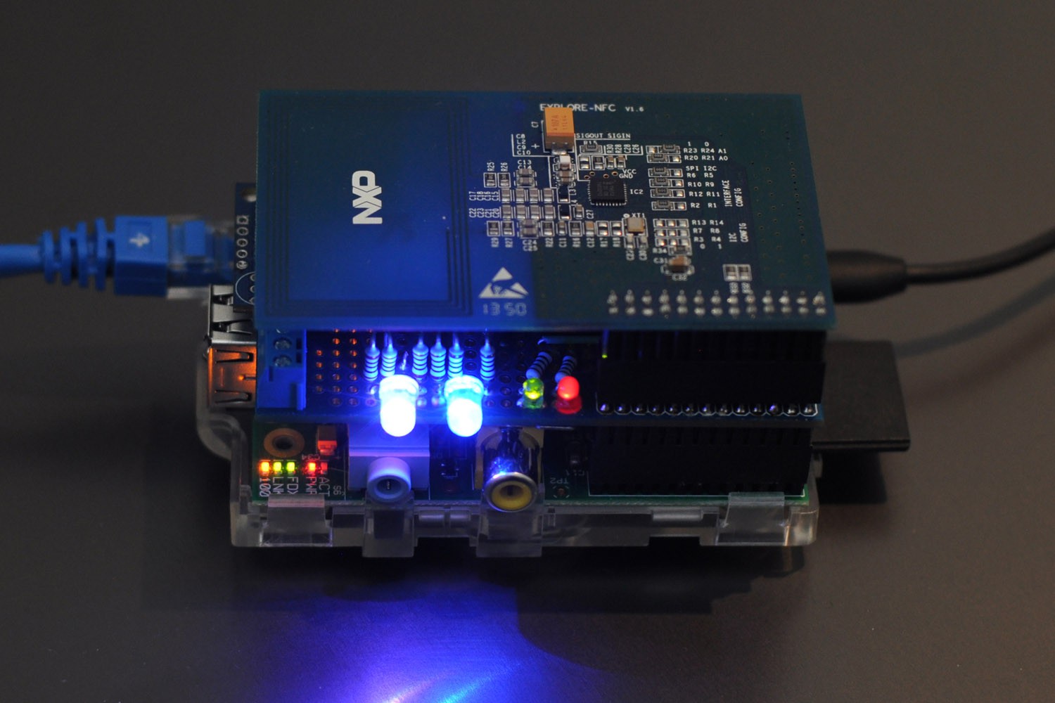
I added two common anode RGB LEDs (the PCA9531PW sinks current) and two status LEDs to the mix:

This completes the hardware setup:

I won't be adding the buffer chips in this prototype version, but they will end up in the final PCB design.
Note that there is an individual resistor for each RGB LED leg. This is so you don't get variations in brightness when you switch different colours on. Of note, the LEDs won't be the primary method of displaying information to the user. The HDMI/composite output can also display things such as balance information and status.
I'll have an updated schematic shortly.
 Blecky
Discussions
Become a Hackaday.io Member
Create an account to leave a comment. Already have an account? Log In.