Close
0%
0%

OURTicket

Open, Universal, Reliable Transport Ticketing.

Similar projects worth following
Since living in Melbourne, many have been frustrated at the lack of improvement and inherent design flaws in the smartcard ticketing system that the local government has rolled out over the last few years.

This project promises to implement an independent solution to these issues by releasing an open source, easy to use, hardware and software (web) framework, that will deliver a complete smart ticketing system for new (and possibly existing) deployments (not limited to transportation). Such a system would enable small or large municipalities to focus on offering excellent transport services, rather than spending tax payer dollars towards the development of ticketing infrastructure that continues to repeat the mistakes of other operators.

OURTicket aims to be completely open, with future scope for exhaustive customisation options. The project while ambitious, begs the involvement and feedback from users and developers, to help create a universal ticketing solution for all.

The main focus of this project was originally to create a multipurpose ticketing system utilising as many open source tools as possible. This could be used in any way for things such as event management, transportation, space travel etc. To reduce the scope I have decided to create a modular system that first focused on transportation, but could be modified easily to perform other tasks. For the purposes of the Hackaday Prize, only the card reader hardware, database connectivity and simple zone management (GIS web service) will be implemented. This working proof of concept will enable further development as time goes on. 

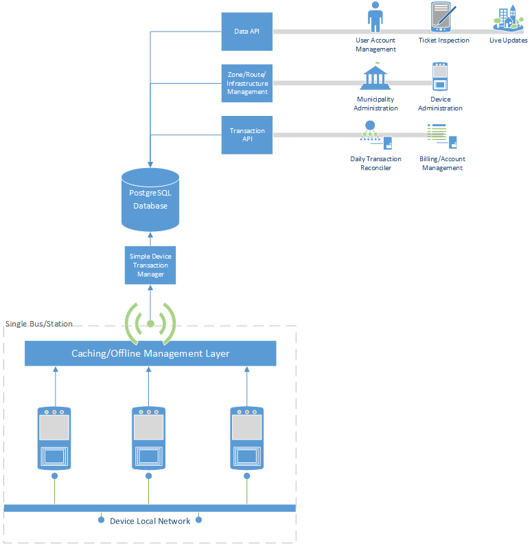
System Block Diagrams

Overall System:
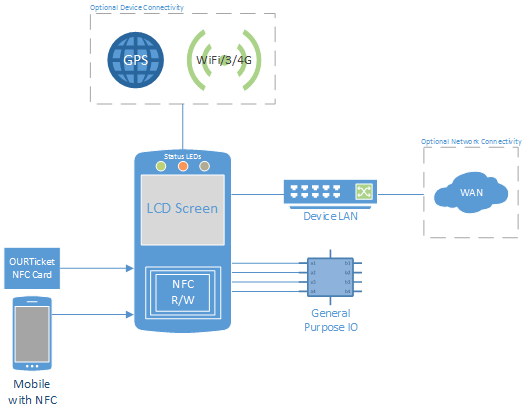
Card Readers:
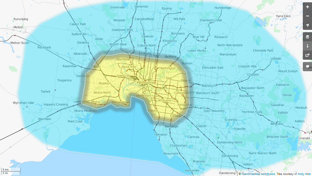
Web Management:
Licenses

NameLicense
DjangoBSD License
GeoDjangoBSD License
PythonPSFL
RaspbianGPL (mostly)
PostgreSQLPostgreSQL License
PostGISGPL
py-postgresqlBSD License
cythonApache License
NXP NFC SoftwareLicensed for use with PN512 Only.

"This NXP Semiconductors IC is ISO/IEC 14443 Type B
software enabled and is licensed under Innovatron’s
Contactless Card patents license for ISO/IEC 14443 B.
The license includes the right to use the IC in systems
and/or end-user equipment."

The OURTicket project and all of it's sources is released under GPL.

  • 2 × Raspberry Pi Model B While this has been chosen for the prototype, the focus is on interface design and the end result will be hardware agnostic.
  • 2 × EXPLORE-NFC Board (NXP PN512) This is used for the prototype. Before the end of the competition a hardware interface board will be designed to accomodate mulitple devices (GPIO/NFC/LED status/sound/serial connectivity for things like proximity detector/RTC/FRAM).
  • 1 × Fujitsu MB85RC128APNF-G-JNE1 FRAM - Ferroelectric RAM for temporary transaction queue storage
  • 1 × Microchip MCP7940N or Maxim DS1307 Real time clock
  • 1 × NXP PCA9531PW LED Controller

View all 11 components

  • Project Description

    Blecky08/20/2014 at 12:30 0 comments

  • LED Demo 2

    Blecky08/18/2014 at 10:50 0 comments

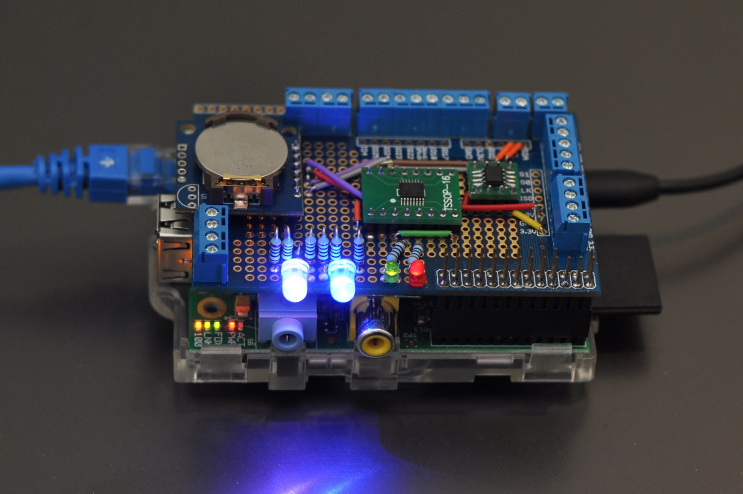
    A demo showing the LEDs working with the device as a whole (green is touch on/off, red is cancel).

  • Updated Schematic

    Blecky08/16/2014 at 10:02 0 comments

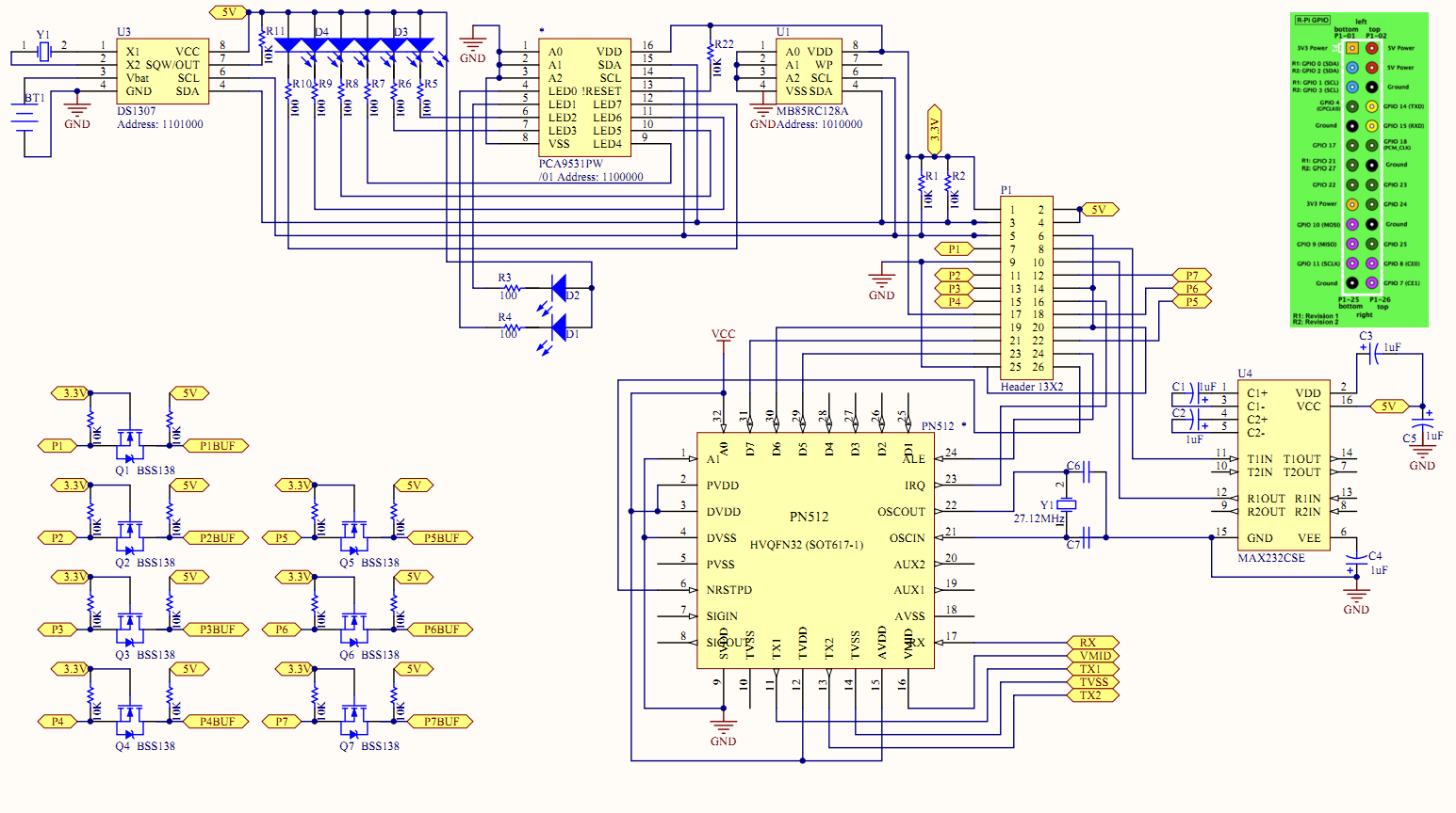
    Note that the green "active" LED (D1) should be connected to LED0 on the PCA9531 as it seems to have a weird bug where it will flicker when other LEDs are flashing. If it is always on, the flickering never happens on the LED0 pin. For the Red LED, you should use a 150ohm resistor (but check the datasheet for the RGB LED and do the calcs).

  • Putting it Together Part 3

    Blecky08/16/2014 at 06:55 0 comments

    I added two common anode RGB LEDs (the PCA9531PW sinks current) and two status LEDs to the mix:

    Read more »

  • Putting it Together Part 2

    Blecky08/15/2014 at 19:22 0 comments

    So after all that testing, I can now solder it all together on a prototyping board.

    Read more »

  • Putting it Together

    Blecky08/15/2014 at 15:59 0 comments

    If you recall, I was going to run into issues with the Explore NFC board since it utilised the same pins as the I2C bus. 

    Well after claiming I solved it, it was worth testing things to see if they would still work as planned.

    I connected the board up without connecting GPIO2 (GPIO0/SDA) and all the other pins. 

    Read more »

  • LED Demo

    Blecky08/14/2014 at 17:00 0 comments

    Well the LEDs work a treat too (datasheet). The following code cycles through each LED as shown in the video:

    #!/usr/bin/python

    import smbus
    from time import sleep

    bus = smbus.SMBus(1) # 0 = /dev/i2c-0 (port I2C0), 1 = /dev/i2c-1 (port I2C1)

    LED_ADDRESS = 0x60 #7 bit address without r/w bit (will be left shifted automatically)

    i = 0
    while (1):
    bus.write_i2c_block_data(LED_ADDRESS, 0x15,[ 0x02, 0x00 ])

    if (i == 0): bus.write_i2c_block_data(LED_ADDRESS, 0x15,[ 0x01, 0x00 ]) #LED 0 = on
    if (i == 1): bus.write_i2c_block_data(LED_ADDRESS, 0x15,[ 0x04, 0x00 ]) #LED 1 = on
    if (i == 2): bus.write_i2c_block_data(LED_ADDRESS, 0x15,[ 0x10, 0x00 ]) #LED 2 = on
    if (i == 3): bus.write_i2c_block_data(LED_ADDRESS, 0x15,[ 0x40, 0x00 ]) #LED 3 = on

    if (i == 4): bus.write_i2c_block_data(LED_ADDRESS, 0x15,[ 0x00, 0x01 ]) #LED 4 = on
    if (i == 5): bus.write_i2c_block_data(LED_ADDRESS, 0x15,[ 0x00, 0x04 ]) #LED 5 = on
    if (i == 6): bus.write_i2c_block_data(LED_ADDRESS, 0x15,[ 0x00, 0x10 ]) #LED 6 = on
    if (i == 7): bus.write_i2c_block_data(LED_ADDRESS, 0x15,[ 0x00, 0x40 ]) #LED 7 = on

    i = i + 1
    if (i == 8): i = 0
    sleep(1)

  • FRAM Working

    Blecky08/14/2014 at 02:11 0 comments

    Just a quick one. The FRAM works basically out of the box with the smbus library in python and the information in the datasheet.

    #!/usr/bin/python
    
    import smbus
    
    bus = smbus.SMBus(1)    # 0 = /dev/i2c-0 (port I2C0), 1 = /dev/i2c-1 (port I2C1)
    
    FRAM_ADDRESS = 0x50     #7 bit address without r/w bit (will be left shifted automatically)
    
    bus.write_i2c_block_data(FRAM_ADDRESS, 0x00,[ 0x00, 0x00, 0x01, 0x02, 0x03, 0x04, 0x05, 0x06, 0x07 ]) #Write 0 - 7 from address 0
    bus.write_i2c_block_data(FRAM_ADDRESS, 0x00, [0x00] )       #Set read position to 0 (address auto-increments each operation)
    print bus.read_i2c_block_data(FRAM_ADDRESS, 0x00)           #Read from 0 and print

    This should yield:

    pi@ourticket-a ~ $ sudo python fram.py
    [0, 1, 2, 3, 4, 5, 6, 7, 0, 0, 0, 0, 0, 0, 0, 0, 0, 0, 0, 0, 0, 0, 0, 0, 0, 0, 0, 0, 0, 0, 0, 0]
    

  • The Hardware Lives!

    Blecky08/13/2014 at 13:19 0 comments

    Sorry for not updating. I went snowboarding over the weekend in Falls Creek and managed to injure my coccyx. I'm steadily able to walk again and get back onto the project.

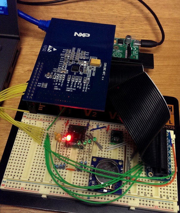
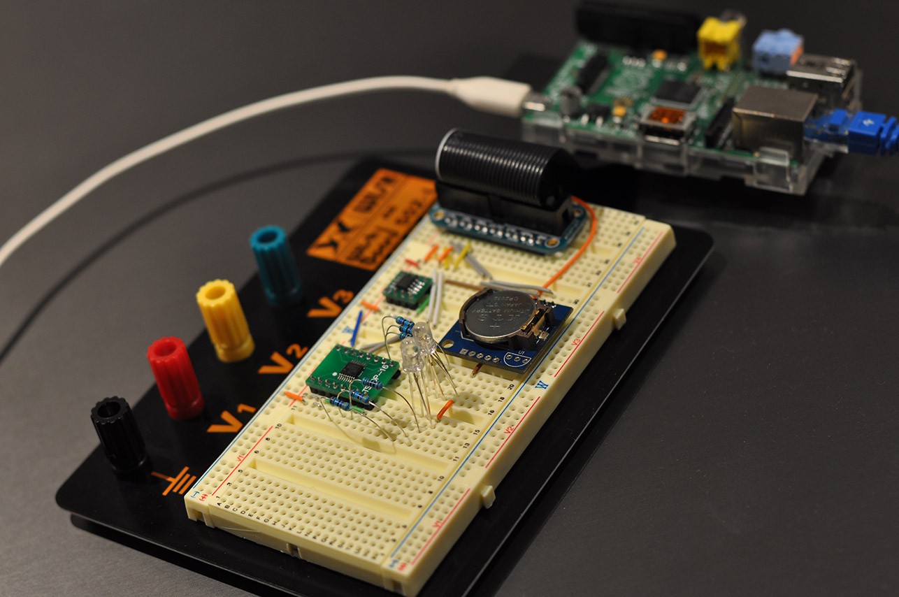
    I have managed to get all the parts breadboarded up:

    Here you can see the FRAM (top), LED controller (left) and RTC (right). The RTC for the moment is a Tiny RTC board (with DS1307) that I had laying about. These can be had on Ebay for a few dollars. The other two chips are mounted with DIP converters.

    Once connected to the Raspberry Pi, you can start to poll for the devices to see if they are wired up correctly. First we have to install i2c tools and enable i2c:

    sudo apt-get update
    
    sudo apt-get install python-smbus
    
    sudo apt-get install i2c-tools
    
    sudo vi /etc/modprobe.d/raspi-blacklist.conf
    Comment out line "blacklist i2c-bcm2708" (with #)
    
    sudo vi /etc/modules
    Add i2c-dev to the end of the list

    Now reboot. Once rebooted you can run the following (use -y 0 for rev 1 boards):

    pi@ourticket-a ~ $ sudo i2cdetect -y 1
         0  1  2  3  4  5  6  7  8  9  a  b  c  d  e  f
    00:          -- -- -- -- -- -- -- -- -- -- -- -- --
    10: -- -- -- -- -- -- -- -- -- -- -- -- -- -- -- --
    20: -- -- -- -- -- -- -- -- -- -- -- -- -- -- -- --
    30: -- -- -- -- -- -- -- -- -- -- -- -- -- -- -- --
    40: -- -- -- -- -- -- -- -- -- -- -- -- -- -- -- --
    50: 50 -- -- -- -- -- -- -- -- -- -- -- -- -- -- --
    60: 60 -- -- -- -- -- -- -- 68 -- -- -- -- -- -- --
    70: -- -- -- -- -- -- -- --

    Note the three addresses that show up. From this we can work out what devices we can see (these values are in hexadecimal). From the schematic:

    0x50 = 1010000 = MB85RC128
    0x60 = 1100000 = PCA9531PW
    0x68 = 1101000 = DS1307

    All the devices are there!

    Edit:

    There should be a 10K pullup resistor on the !Reset pin of the PCA9531PW. I will fix the schematic soon.

  • Keep Backups and Version Control

    Blecky07/27/2014 at 15:29 0 comments

    No update today as I was recovering all my main PC's data from a backup most of the afternoon.

    I just want to express the importance of keeping backups of all of your data for the project. I currently have a git repo on my NAS (and it will shortly be put online when I get a better internet connection). I usually push to this whenever I can. I was lucky since I only lost a couple of hours of work when my local machine's drive comepletely failed catastrophically while working on it.

    I was able to recover this easily once I got my machine back up and running. This repo is also rsynced daily to another external drive, just in case my NAS decides to fail.

    Keep backups!

View all 15 project logs

Enjoy this project?

Share

Discussions

ihaabi wrote 10/28/2014 at 13:05 point
Hello, Great Job Man, specially the description and schematic explanation. I am trying to integrate Explore NFC with LPC1114 and I need a small help in this regard. By any chance do you have any command set for PN512 in c format (such as accessing different registers), or know any place from where I could get it. Thanks buddy

  Are you sure? yes | no

Blecky wrote 10/28/2014 at 14:26 point
I initially adapted some of the code from these sources:

https://github.com/robinmonjo/explore-nfc-board-driver

This code provides additional functionality to the NXP PN512 demo libraries and source (http://www.nxp.com/demoboard/PNEV512R.html#documentation).

There isn't a specific "command set" per se, the operation of this device (and most NXP devices) works by sending a control register and the device responds. It's not like a typical human readable serial interface that you see on micro-controllers for example.

Unfortunately in terms of accessing certain registers, you're going to have to use the datasheet to get specific values. It all depends on what you are trying to do.

If this is your first foray into SPI/I2C devices, I suggest you adapt the code above for your needs. The datasheet, while daunting and confusing at first, does in fact give you all the information you need. It just takes time to sit down and work out what you require from the device first.

I will continue to work on this project next year and release better sources, life just eats your time :P

  Are you sure? yes | no

davedarko wrote 08/26/2014 at 00:04 point
Will you incorporate the specifications for the raspberry pi hats or will you leave it a non-HAT shield? Great ambitious project by the way :)

  Are you sure? yes | no

Blecky wrote 08/26/2014 at 00:38 point
I'm not sure what you mean by hat shield :(

  Are you sure? yes | no

Blecky wrote 08/26/2014 at 01:19 point
I will eventually be creating a new board that incorporates everything. The devices shown here are purely prototypes. I want to get the software side of things sorted next.

  Are you sure? yes | no

davedarko wrote 08/26/2014 at 08:35 point
http://hackaday.com/2014/08/22/introducing-hat-a-day-not-to-be-confused-with-the-real-had-of-course/ it does not seem necessary though.

I'm looking forward to see this board :)

  Are you sure? yes | no

Blecky wrote 08/28/2014 at 01:51 point
Ha, completely missed that. Might as well I guess :P

  Are you sure? yes | no

Similar Projects

Does this project spark your interest?

Become a member to follow this project and never miss any updates