-
Project Description
08/20/2014 at 12:30 • 0 comments -
LED Demo 2
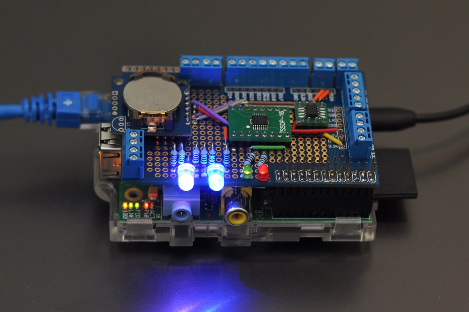
08/18/2014 at 10:50 • 0 commentsA demo showing the LEDs working with the device as a whole (green is touch on/off, red is cancel).
-
Updated Schematic
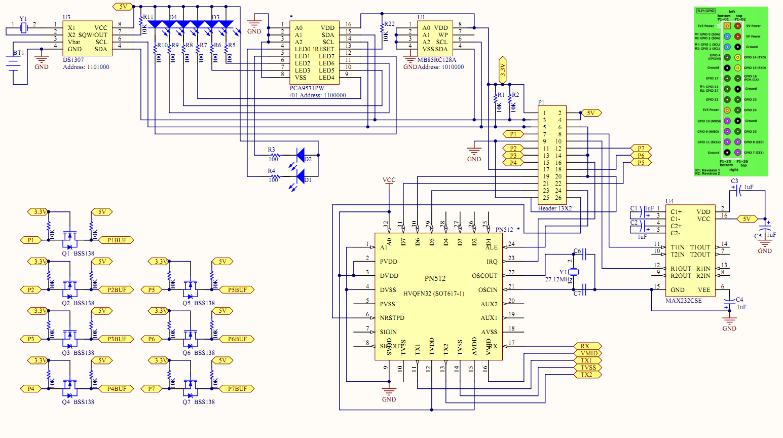
08/16/2014 at 10:02 • 0 commentsNote that the green "active" LED (D1) should be connected to LED0 on the PCA9531 as it seems to have a weird bug where it will flicker when other LEDs are flashing. If it is always on, the flickering never happens on the LED0 pin. For the Red LED, you should use a 150ohm resistor (but check the datasheet for the RGB LED and do the calcs).
-
Putting it Together Part 3
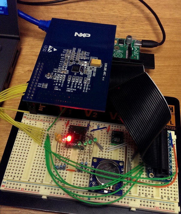
08/16/2014 at 06:55 • 0 commentsI added two common anode RGB LEDs (the PCA9531PW sinks current) and two status LEDs to the mix:
This completes the hardware setup:
I won't be adding the buffer chips in this prototype version, but they will end up in the final PCB design.
Note that there is an individual resistor for each RGB LED leg. This is so you don't get variations in brightness when you switch different colours on. Of note, the LEDs won't be the primary method of displaying information to the user. The HDMI/composite output can also display things such as balance information and status.
I'll have an updated schematic shortly.
-
Putting it Together Part 2
08/15/2014 at 19:22 • 0 comments -
Putting it Together
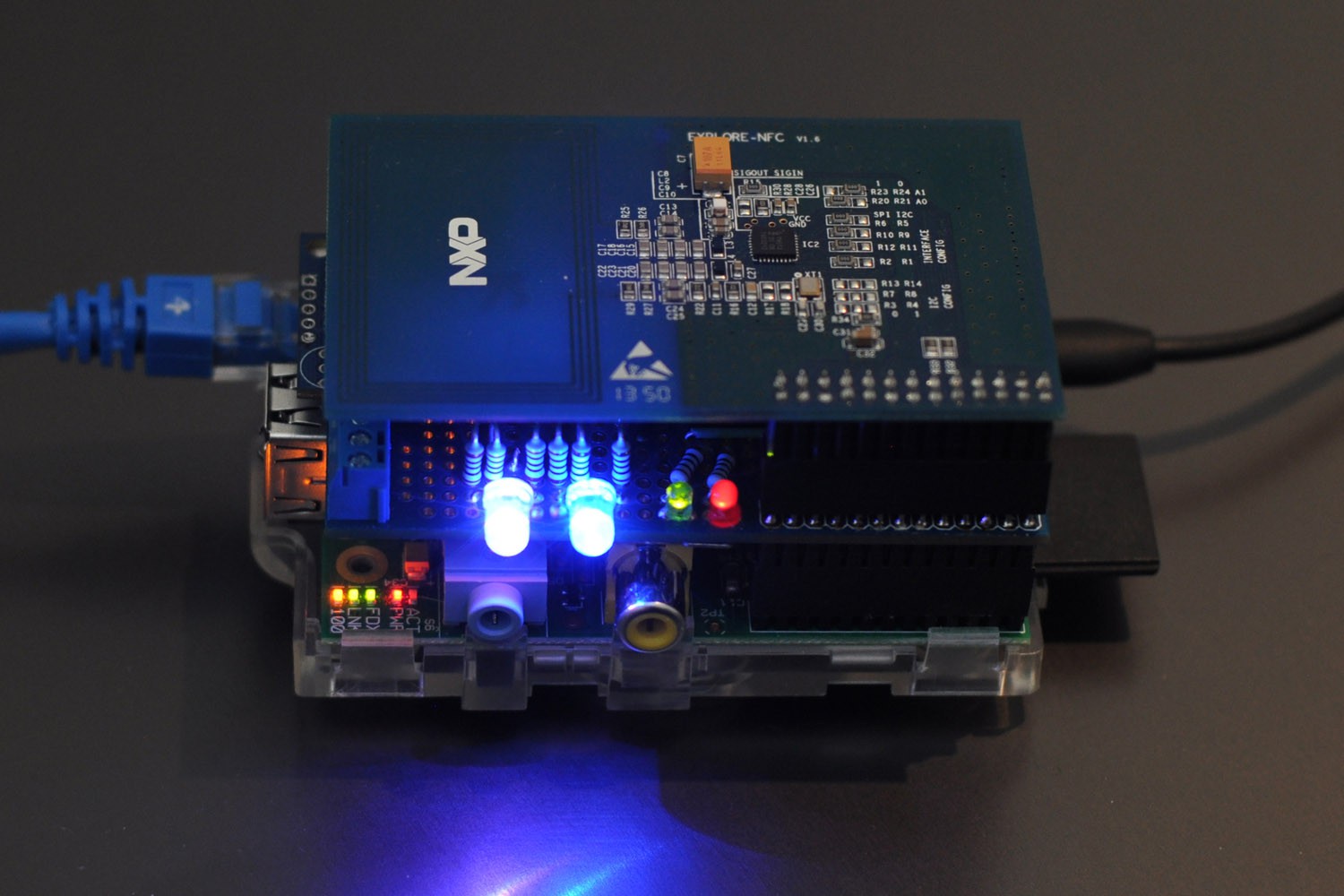
08/15/2014 at 15:59 • 0 commentsIf you recall, I was going to run into issues with the Explore NFC board since it utilised the same pins as the I2C bus.
Well after claiming I solved it, it was worth testing things to see if they would still work as planned.
I connected the board up without connecting GPIO2 (GPIO0/SDA) and all the other pins.
An additional change is required in NXP's source code. In NxpRdLib_PublicRelease/comps/phbalReg/src/R_Pi_spi/phbalReg_R_Pi_spi.c you will need to change:
if (boardRev == 1)
{
    ifsel_fd = open("/sys/class/gpio/gpio0/direction",O_WRONLY);
}
else
{
    ifsel_fd = open("/sys/class/gpio/gpio2/direction",O_WRONLY);
}
To:
ifsel_fd = open("/sys/class/gpio/gpio8/direction",O_WRONLY);Obviously this would be different if you decided to use I2C for this, so this change is purely for the SPI implementation.
Fire up the test code and run the polling software:
pi@ourticket-a ~ $ sudo python ledtest.py &
[1] 2262
pi@ourticket-a ~ $ sudo python fram.py
[0, 1, 2, 3, 4, 5, 6, 7, 0, 0, 0, 0, 0, 0, 0, 0, 0, 0, 0, 0, 0, 0, 0, 0, 0, 0, 0, 0, 0, 0, 0, 0]
pi@ourticket-a ~ $ sudo python concept.py
Getting location from GPSD.
Stored transaction in local queue: ##############*20140814-042212*1*ourticket-a*-37.814107*144.96328*B222E7*B606*1toVRqEzEpNhaTBmi8kqqw==
Touch on complete.
Everything should continue to work without hanging or acting erratically (without the NXP source change change, the LEDs will stop). Note, that I won't be performing I2C transactions independently like above, they will be handled one after the other at appropriate times, but for this demo it still works.
-
LED Demo
08/14/2014 at 17:00 • 0 commentsWell the LEDs work a treat too (datasheet). The following code cycles through each LED as shown in the video:
#!/usr/bin/python

import smbus
from time import sleep

bus = smbus.SMBus(1)  # 0 = /dev/i2c-0 (port I2C0), 1 = /dev/i2c-1 (port I2C1)

LED_ADDRESS = 0x60  #7 bit address without r/w bit (will be left shifted automatically)

i = 0
while (1):
  bus.write_i2c_block_data(LED_ADDRESS, 0x15,[ 0x02, 0x00 ])

  if (i == 0): bus.write_i2c_block_data(LED_ADDRESS, 0x15,[ 0x01, 0x00 ]) #LED 0 = on
  if (i == 1): bus.write_i2c_block_data(LED_ADDRESS, 0x15,[ 0x04, 0x00 ]) #LED 1 = on
  if (i == 2): bus.write_i2c_block_data(LED_ADDRESS, 0x15,[ 0x10, 0x00 ]) #LED 2 = on
  if (i == 3): bus.write_i2c_block_data(LED_ADDRESS, 0x15,[ 0x40, 0x00 ]) #LED 3 = on

  if (i == 4): bus.write_i2c_block_data(LED_ADDRESS, 0x15,[ 0x00, 0x01 ]) #LED 4 = on
  if (i == 5): bus.write_i2c_block_data(LED_ADDRESS, 0x15,[ 0x00, 0x04 ]) #LED 5 = on
  if (i == 6): bus.write_i2c_block_data(LED_ADDRESS, 0x15,[ 0x00, 0x10 ]) #LED 6 = on
  if (i == 7): bus.write_i2c_block_data(LED_ADDRESS, 0x15,[ 0x00, 0x40 ]) #LED 7 = on

  i = i + 1
  if (i == 8): i = 0
sleep(1) -
FRAM Working
08/14/2014 at 02:11 • 0 commentsJust a quick one. The FRAM works basically out of the box with the smbus library in python and the information in the datasheet.
#!/usr/bin/python

import smbus

bus = smbus.SMBus(1)    # 0 = /dev/i2c-0 (port I2C0), 1 = /dev/i2c-1 (port I2C1)

FRAM_ADDRESS = 0x50     #7 bit address without r/w bit (will be left shifted automatically)

bus.write_i2c_block_data(FRAM_ADDRESS, 0x00,[ 0x00, 0x00, 0x01, 0x02, 0x03, 0x04, 0x05, 0x06, 0x07 ]) #Write 0 - 7 from address 0
bus.write_i2c_block_data(FRAM_ADDRESS, 0x00, [0x00] )       #Set read position to 0 (address auto-increments each operation)
print bus.read_i2c_block_data(FRAM_ADDRESS, 0x00)           #Read from 0 and print
This should yield:
pi@ourticket-a ~ $ sudo python fram.py
[0, 1, 2, 3, 4, 5, 6, 7, 0, 0, 0, 0, 0, 0, 0, 0, 0, 0, 0, 0, 0, 0, 0, 0, 0, 0, 0, 0, 0, 0, 0, 0]
-
The Hardware Lives!
08/13/2014 at 13:19 • 0 commentsSorry for not updating. I went snowboarding over the weekend in Falls Creek and managed to injure my coccyx. I'm steadily able to walk again and get back onto the project.
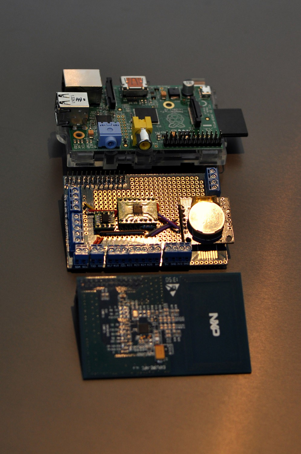
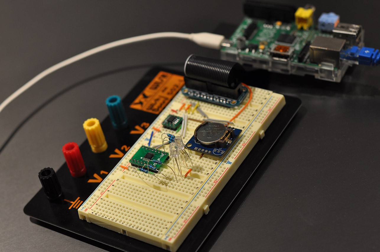
I have managed to get all the parts breadboarded up:
Here you can see the FRAM (top), LED controller (left) and RTC (right). The RTC for the moment is a Tiny RTC board (with DS1307) that I had laying about. These can be had on Ebay for a few dollars. The other two chips are mounted with DIP converters.
Once connected to the Raspberry Pi, you can start to poll for the devices to see if they are wired up correctly. First we have to install i2c tools and enable i2c:
sudo apt-get update

sudo apt-get install python-smbus

sudo apt-get install i2c-tools

sudo vi /etc/modprobe.d/raspi-blacklist.conf
Comment out line "blacklist i2c-bcm2708" (with #)

sudo vi /etc/modules
Add i2c-dev to the end of the list
Now reboot. Once rebooted you can run the following (use -y 0 for rev 1 boards):
pi@ourticket-a ~ $ sudo i2cdetect -y 1
     0  1  2  3  4  5  6  7  8  9  a  b  c  d  e  f
00:          -- -- -- -- -- -- -- -- -- -- -- -- --
10: -- -- -- -- -- -- -- -- -- -- -- -- -- -- -- --
20: -- -- -- -- -- -- -- -- -- -- -- -- -- -- -- --
30: -- -- -- -- -- -- -- -- -- -- -- -- -- -- -- --
40: -- -- -- -- -- -- -- -- -- -- -- -- -- -- -- --
50: 50 -- -- -- -- -- -- -- -- -- -- -- -- -- -- --
60: 60 -- -- -- -- -- -- -- 68 -- -- -- -- -- -- --
70: -- -- -- -- -- -- -- --
Note the three addresses that show up. From this we can work out what devices we can see (these values are in hexadecimal). From the schematic:
0x50 = 1010000 = MB85RC128
0x60 = 1100000 = PCA9531PW
0x68 = 1101000 = DS1307
All the devices are there!
Edit:
There should be a 10K pullup resistor on the !Reset pin of the PCA9531PW. I will fix the schematic soon.
-
Keep Backups and Version Control
07/27/2014 at 15:29 • 0 commentsNo update today as I was recovering all my main PC's data from a backup most of the afternoon.
I just want to express the importance of keeping backups of all of your data for the project. I currently have a git repo on my NAS (and it will shortly be put online when I get a better internet connection). I usually push to this whenever I can. I was lucky since I only lost a couple of hours of work when my local machine's drive comepletely failed catastrophically while working on it.
I was able to recover this easily once I got my machine back up and running. This repo is also rsynced daily to another external drive, just in case my NAS decides to fail.
Keep backups!
 Blecky