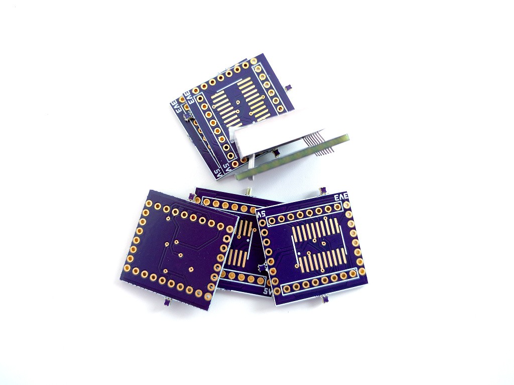
So the boards finally arrived from OSHPark (but without the stickers). I immediately tried the matrices to see if they fit. They don't. When I designed the PCB, I assumed that the pins are along the edge of the matrix. Which is stupid, because I had the matrices already, I could have just checked. They are 1.27mm towards the middle. So you get something like this:

Which isn't that bad for a first prototype. And I was so sure of myself, that I ordered 6 PCBs, because I had 5 matrices and 5 chips, and I wanted to use them all. Sigh.
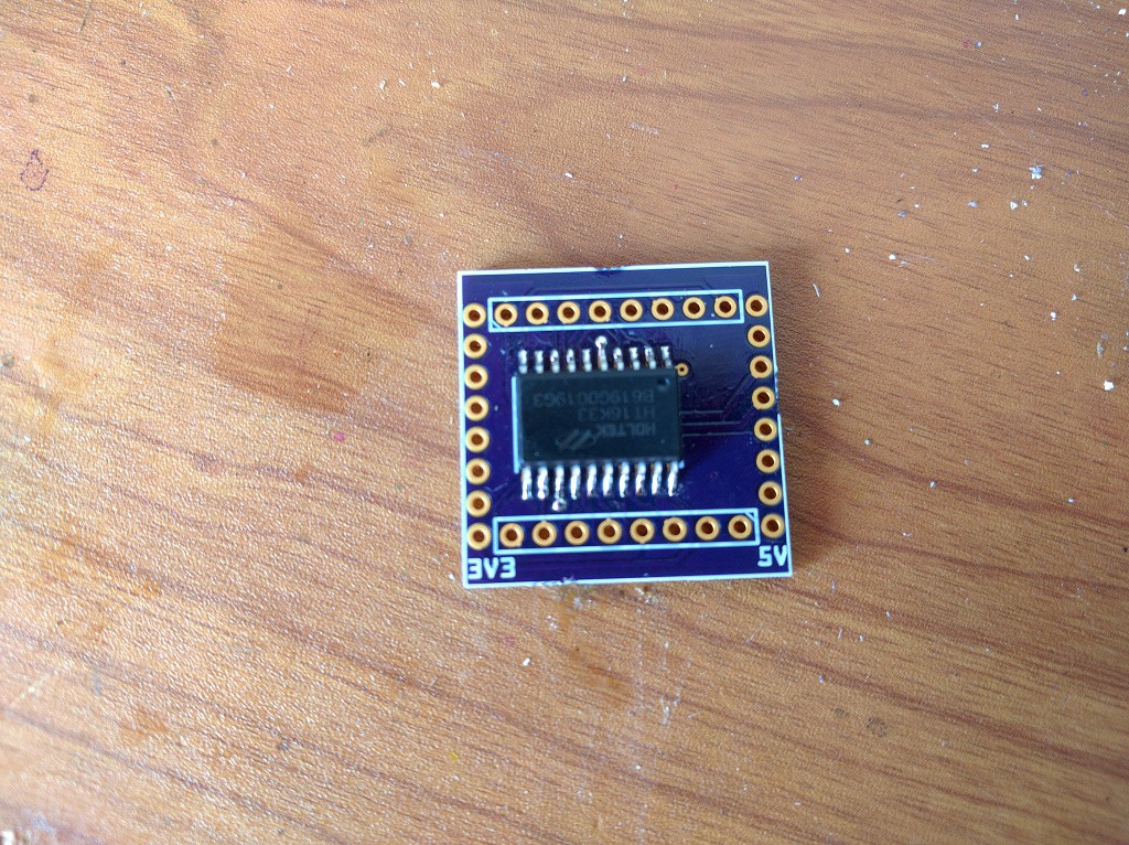
Oh well, at least the chip fits into that footprint:

So I quickly soldered the whole thing, popped it onto my D1 Mini, and tried my driver on this thing. First, an I2C scan, and the device enumerated as 112 -- success! I loaded my library, filled the whole screen with 1, and called the "show" command, and... nothing. No error, the chip behaves as if it executed the command, but no lights. Hmm, maybe I put the matrix the wrong way?
I replaced the matrix the other way, tried it, and now... I2C scan shows all addresses, the chip accepts all commands, but nothing happens. Removed the matrix didn't fix it -- the scan still shows all addresses. I think I broke it.
But I have 4 more. So I tried different things, with the matrix and without, and now I have 4 broken chips...
I think I'm going to call it a day, and try with the last chip (really carefully this time) when I feel a bit better.
 deʃhipu
Discussions
Become a Hackaday.io Member
Create an account to leave a comment. Already have an account? Log In.