-
Boards #4
12/13/2016 at 20:58 • 2 commentsMy recent trouble with code for #Servo Breakout for WeMos D1 Mini made me think whether I actually didn't jump to conclusions too fast with those HT16K33 chips. You know what they teach you: before you blame the hardware, the compiler, the operating system or the libraries, make sure that everything on your side is absolutely spotless and correct. I thought I did. I was wrong.
Today I took the Adafruit HUZZAH Feather board, connected one of the non-working matrix shields to its GPIO0 and GPIO2 pins (the ones that have built-in pullups), uploaded my ht16k33_matrix module and tried it, and... it worked. Just like that.
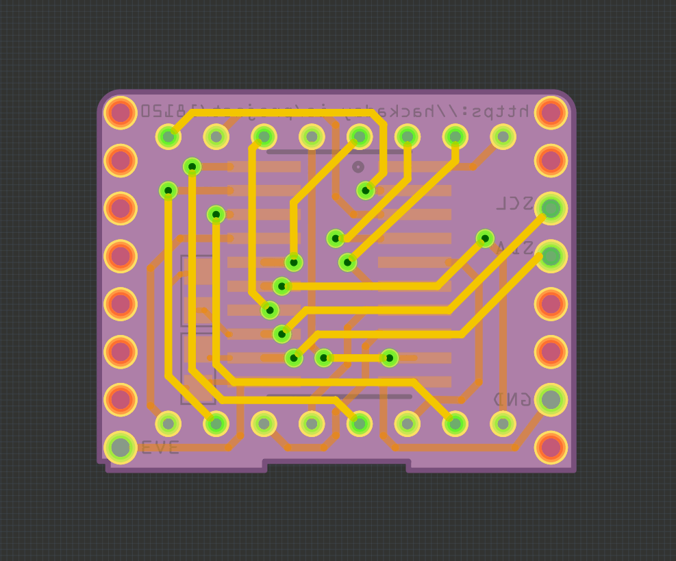
Of course the shields connect to pins GPIO4 and GPIO5 of the D1 Mini, which do not have their own external pullups, so I have no choice but to re-design the PCB again, this time to include footprints for a two additional resistors:
![]()
I will of course "fix" the shields i already have, by simply soldering the resistors straight to the pins -- so the good news is that I will have a bunch of working shields. The bad news is I will have to wait a couple of weeks more to test the new PCBs before I can officially announce this project as working.
-
Boards #3
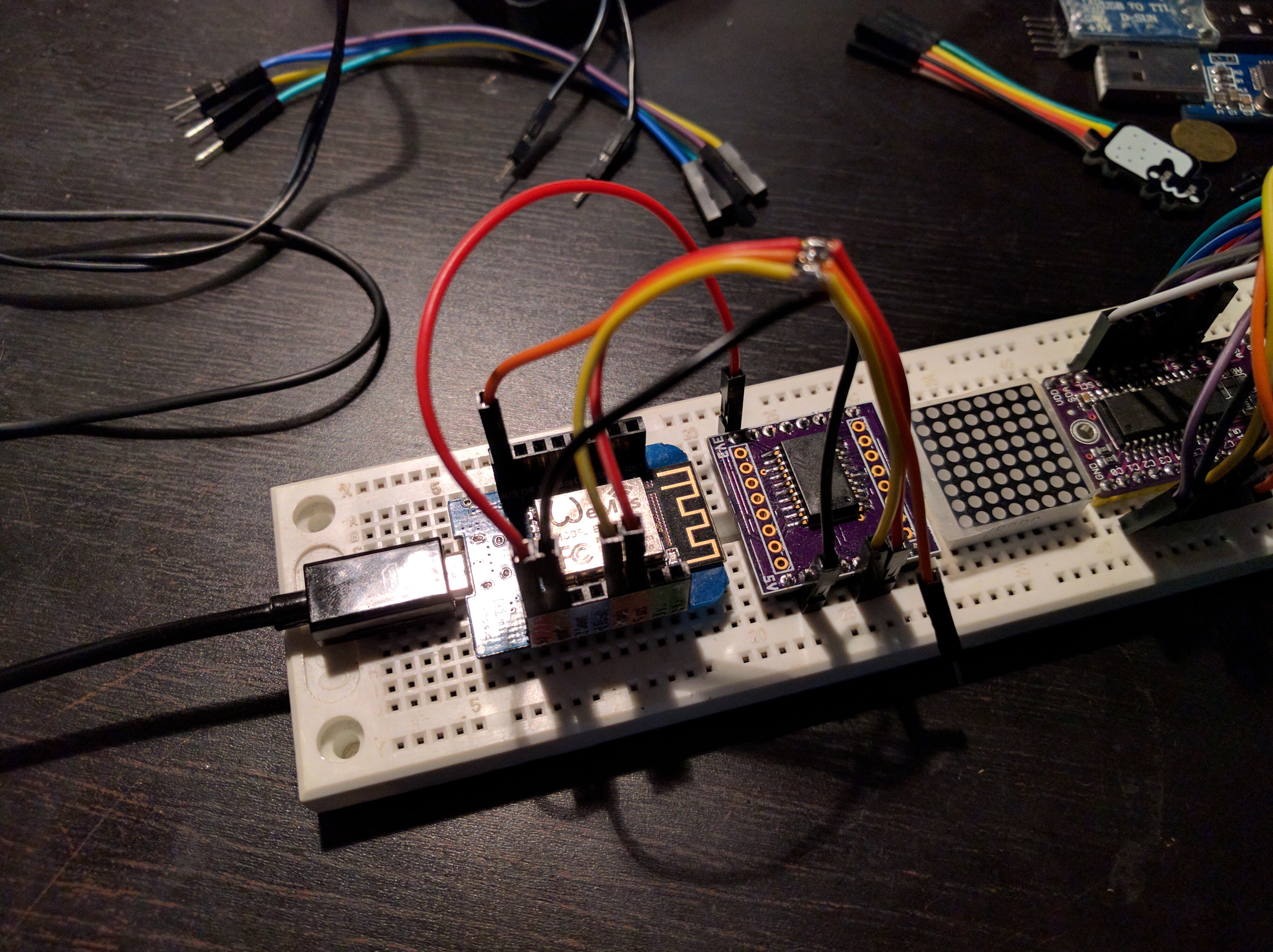
12/02/2016 at 21:27 • 0 commentsI can confirm that the HT16k33 chips I had were most likely faulty. I took one of the remaining unpopulated boards, and carefully checked it for shorts and continuity. It checked fine -- each pad is connected with exactly one hole. Then I took my last remaining chip, and soldered that carefully to the board. Added the pin headers, and plugged that into a breadboard. Then, without connecting any matrix, I carefully connected the wires for power and for I²C (with extra pullup resistors on them), and plugged the whole thing into USB.
![]()
Then I did the I²C scan, and the result is the same as with the other chips. I double-checked the datasheet if there is any need for additional components of any kind for this chip (and also examined the breakout board I have for any extra components). Nothing. It should just be working, and it's not. Ergo -- broken chips.
I ordered a new batch from a different seller this time, and will see how that works. In a few weeks. Perhaps the new PCBs will arrive by that time too.
-
Boards #2
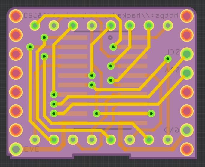
12/01/2016 at 17:35 • 0 commentsn other news, now that I actually know the pin spacing of those matrices, I re-did the PCB design, taking that into account, and also moving the chip on the underside, so that the whole thing is not as thick.
![]()
It's no longer a 1" square, since the different positioning of the chip, generous sprinkling of vias and extra space at the edges left me enough room for all the traces.
-
Boards #1
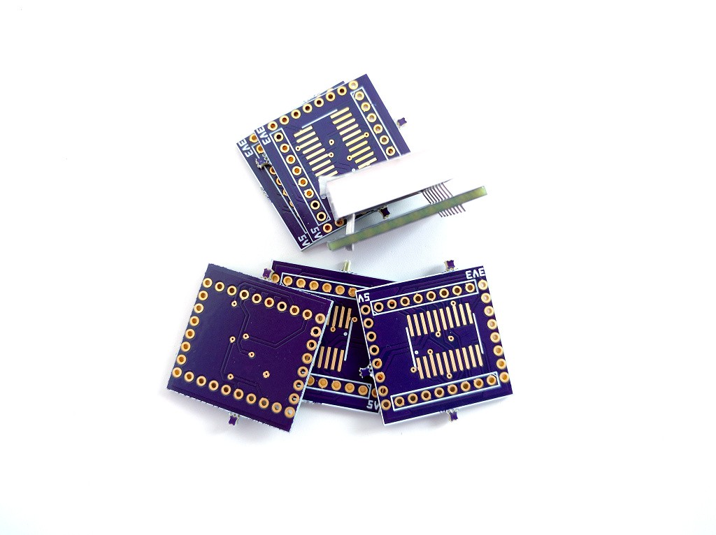
12/01/2016 at 17:30 • 0 commentsSo the boards finally arrived from OSHPark (but without the stickers). I immediately tried the matrices to see if they fit. They don't. When I designed the PCB, I assumed that the pins are along the edge of the matrix. Which is stupid, because I had the matrices already, I could have just checked. They are 1.27mm towards the middle. So you get something like this:
![]()
Which isn't that bad for a first prototype. And I was so sure of myself, that I ordered 6 PCBs, because I had 5 matrices and 5 chips, and I wanted to use them all. Sigh.
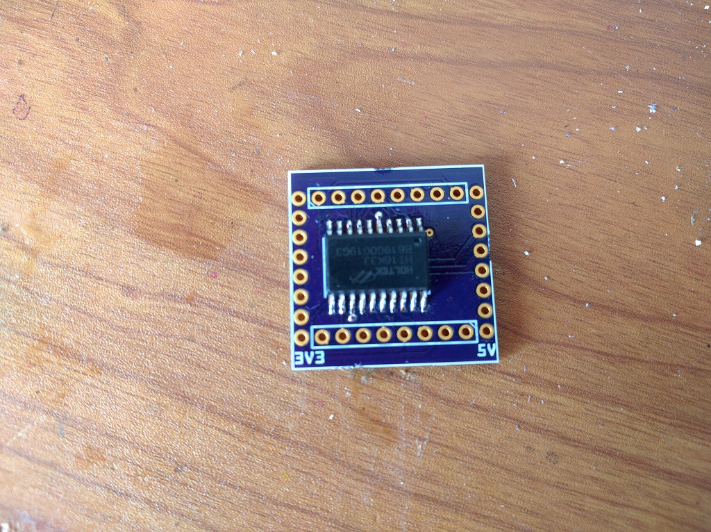
Oh well, at least the chip fits into that footprint:
![]()
So I quickly soldered the whole thing, popped it onto my D1 Mini, and tried my driver on this thing. First, an I2C scan, and the device enumerated as 112 -- success! I loaded my library, filled the whole screen with 1, and called the "show" command, and... nothing. No error, the chip behaves as if it executed the command, but no lights. Hmm, maybe I put the matrix the wrong way?
I replaced the matrix the other way, tried it, and now... I2C scan shows all addresses, the chip accepts all commands, but nothing happens. Removed the matrix didn't fix it -- the scan still shows all addresses. I think I broke it.
But I have 4 more. So I tried different things, with the matrix and without, and now I have 4 broken chips...
I think I'm going to call it a day, and try with the last chip (really carefully this time) when I feel a bit better.
-
Initial Prototype
11/10/2016 at 19:14 • 0 commentsSo, Adafruit has those nice 8x8 LED matrix backpacks, which use I²C for communication and are generally very cool to play with. They even have shields (FeatherWings) for their boards with them. However, in my workshops I'm using D1 Mini boards (mostly because they are cheaper). I decided that it would be very nice to have such a shield for the D1 Mini, so I decided to try to make one.
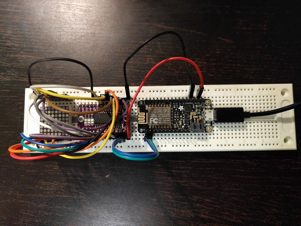
I started by ordering a HT16K33 breakout board, some loose chips in the 20-pin packages, and a handful of those LED matrices. Once they arrived, I assembled a prototype on the breadboard, to make sure I got all the connections right:
![]()
Then I tested it with my HT16K33 MicroPython library. Turns out that the original backpacks are shifted by one column for some reason, so that they start at column 1 and end at column 0 (instead of starting at 0 and ending at 7). Oh well, a quick fix, and my shield is compatible.
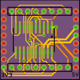
Next, I need to design the actual PCB. To the Fritzing!
![]()
Maybe it's not the simplest thing to route, but it's not too horrible either. I kept all parts on the same side (the chip goes under the matrix), for ease of assembly. Unfortunately the board has to be duble-layer -- there are just too many crossing traces. I wonder why they didn't design those chips to match the matrix pinout better.
The board is exactly one inch by one inch, by the way -- would have been a nice candidate for the one square inch contest.
Next, to OSHPark to order the boards, and now I'm just waiting for them to arrive. Should be here before Christmas.
D1 Mini Matrix Shield
A shield for the D1 Mini ESP8266 board with HT16K33 chip and 8x8 mini LED matrix.
 deʃhipu