 tomtibbetts
-
1Collect Your Parts
Parts:
Quantity Description Link Ext Price 1 SUPERMICRO CSE-502L-200B Black 1U Rackmount Mini Server Chassis 200W SuperMicro Server Chassis 79.99 4 Raspberry Pi 3B or greater 140.00 1 Mini ATX PSU II - Cool - Desktop ATX Power Supply ATX 20/24 Pin configuration 8.5mm mounting kit with 12 VDC fan kit Mini ATX PSU II - Cool - Desktop ATX Power Supply 32.45 3 Mini ATX PSU II - Cool - Desktop ATX Power Supply FDD/SATA configuration 8.5mm mounting kit with 12 VDC fan kit Mini ATX PSU II - Cool - Desktop ATX Power Supply 97.35 4 250GB SSD drive Kingston or Crucial 140.00 4 Startech.com SSD - USB adapter Startech.com SSD - USB Adapter 67.96 4 CAT 5 or 6 ethernet couplers RJ45 Keystone Jack Cat6 Coupler Female to Female 16.99 for 20 pcs 4 CAT 5 or 6 1 foot ethernet patch cable 1' Cat5e Network Ethernet Patch Cable 7.99 for 10 pcs 16 plastic standoffs for the Pi's uxcell M2.5x6mm+6mm Male-Female Hex Nylon Standoffs $9.49 for 150 pcs 1 2.5" drive bracket (aluminium) Super Micro: MCP-220-00051-0N 2.5" drive bracket (aluminium) Super Micro: MCP-220-00051-0N 7.25 1 8-Inch 4 Pin Floppy Drive to 15 Pin SATA Male Power Cable(2-Pack) 8-Inch 4 Pin Floppy Drive to 15 Pin SATA Male Power Cable(2-Pack) 6.99 1 One 5.25 Inch to Two 3.5 Inch Internal Power Y-Cable One 5.25 Inch to Two 3.5 Inch Internal Power Y-Cable 7.11 Total Cost 613.57 -
2Recommended Tools
Tools:
- Various sizes of phillips head screw drivers.
- Drill with the following drill bits:
- 1/2" for drilling pilot holes for the ethernet couplers
- 1/8” for the 3.25mm holes for mounting the SSD drive bracket
- 7/64” for the 2.75mm holes for mounting the Pis
- Thin point nail set for marking drill holes
- 3/16" hex socket driver for tightening standoffs and M2.5 nuts
- Hot melt glue gun for gluing the couplers to the chassis
- 2 3" or 4" C-clamps
- Straight tin snips
- Metal file
- Solder iron and solder
- Wire clippers and strippers
- Small diameter heat shrink
- Misc small zip ties as needed
-
3Building the SSD Bracket for Four SSDs
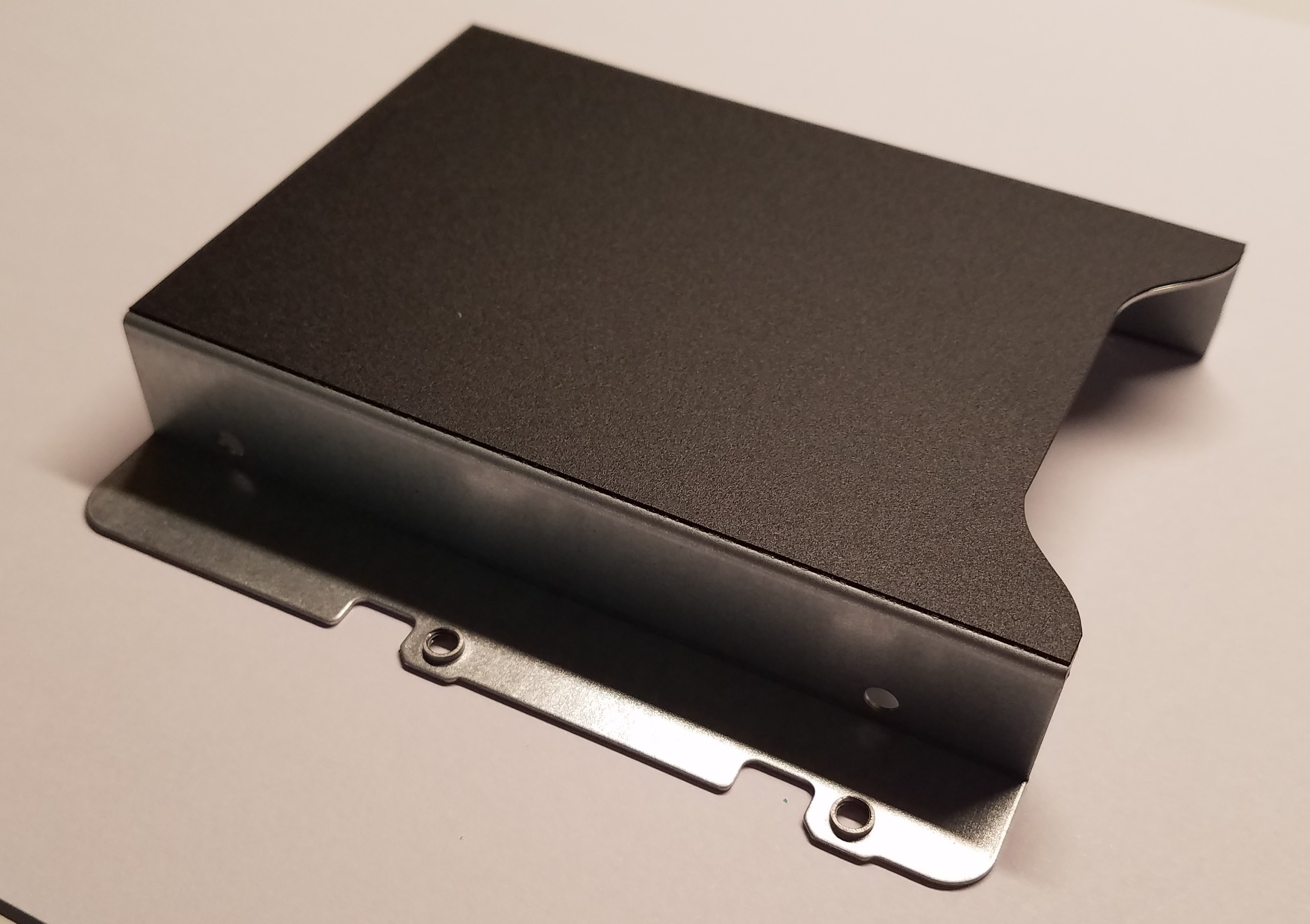
The small footprint and low height of the server chassis forced me to find a creative solution for vertically stacking 4 x 2 1/2 inch SSDs while having some sort of air flow between them. I search all over to find off the shelf brackets that would be under 4.4cm to no avail. So, I had to make my own. I would have preferred 3d printing a bracket but I didn't have access to a 3d printer, so I took a super micro single height bracket and modified it. It already had some the mounting holes I needed and it was relatively easy to work with. It's made of thick aluminum so it will act as a heat sink (something a plastic bracket would not do).
![]()
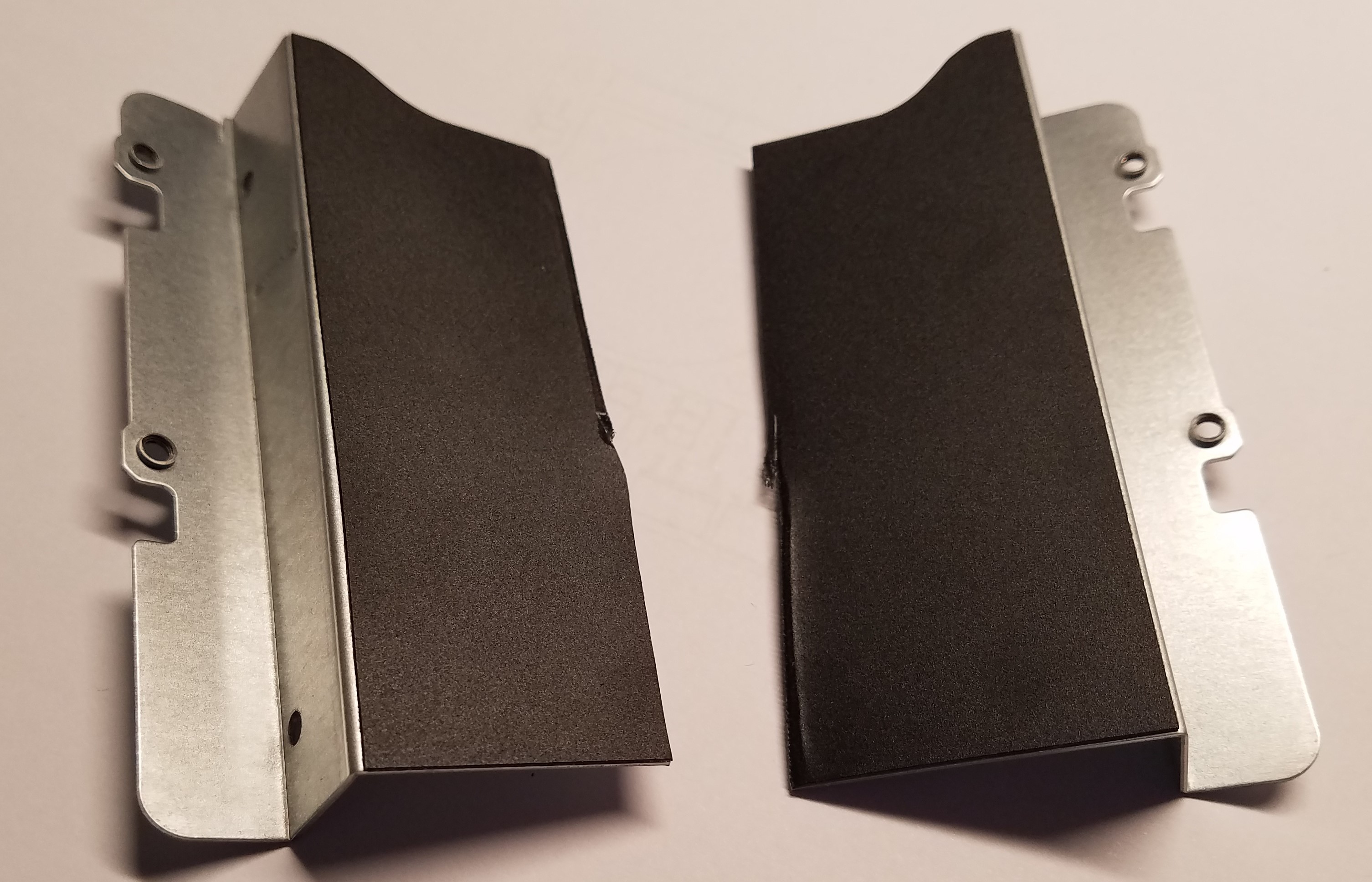
Using straight tin snips (don't use the ones that curve right or left) cut the bracket down the middle as below:
![]()
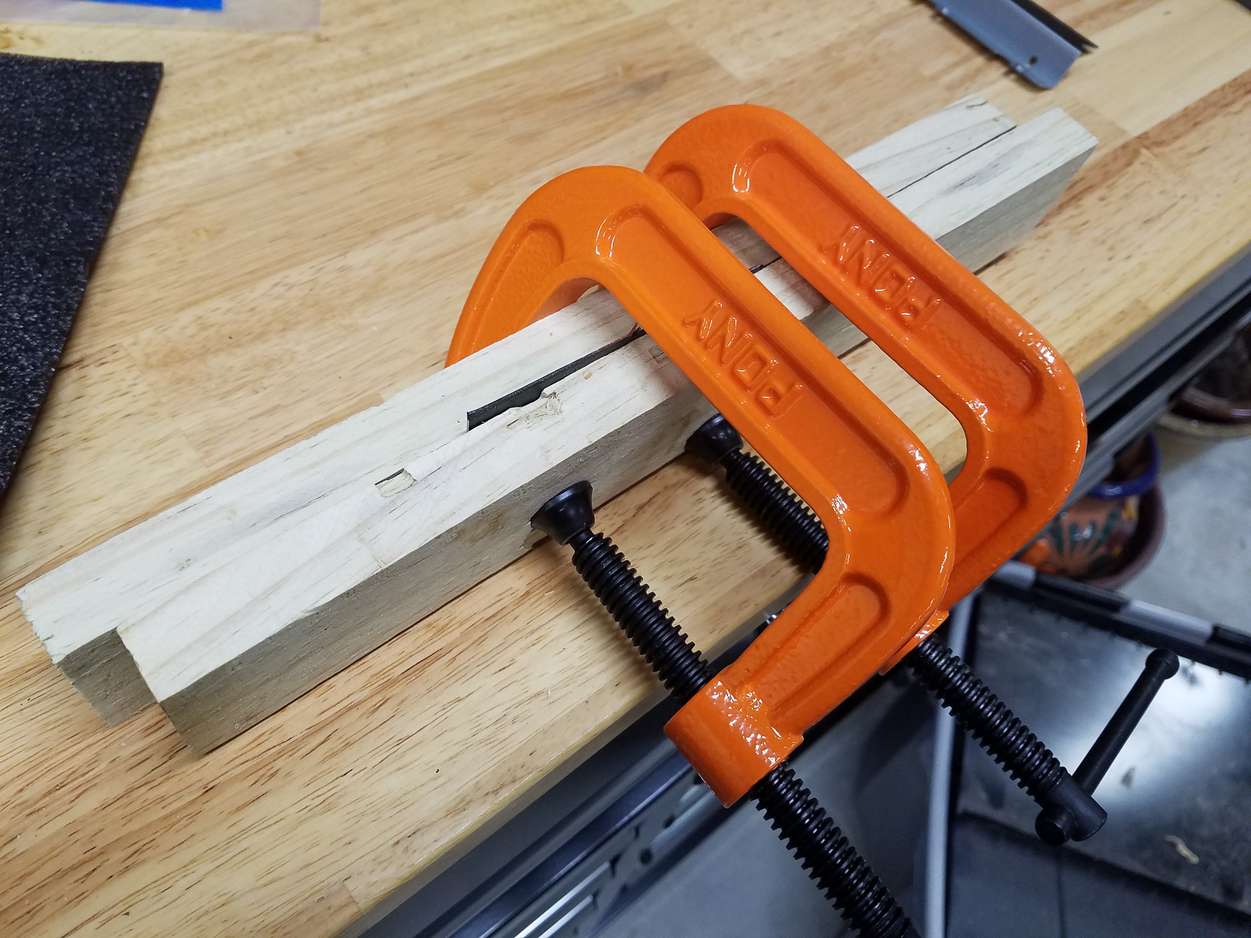
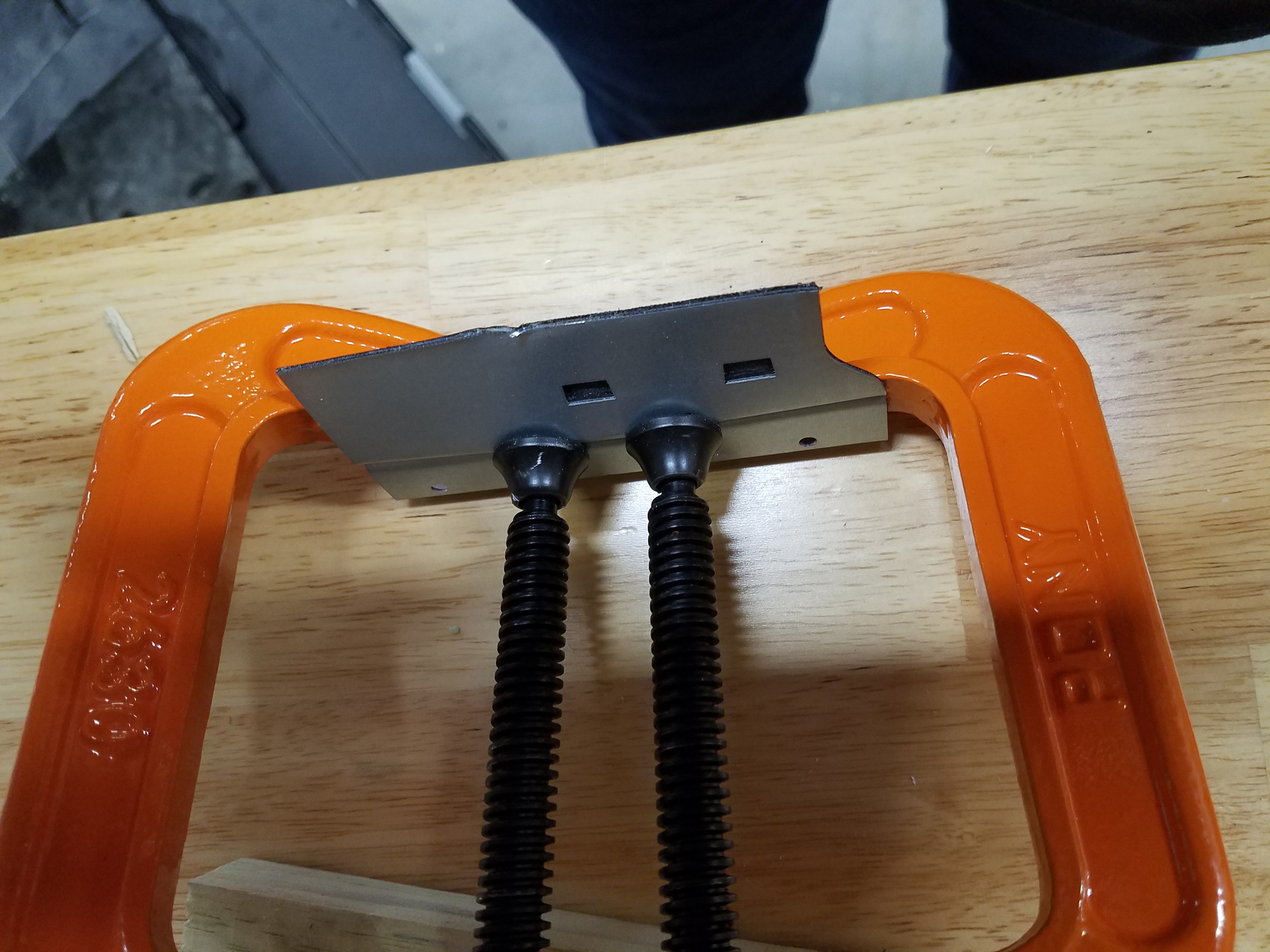
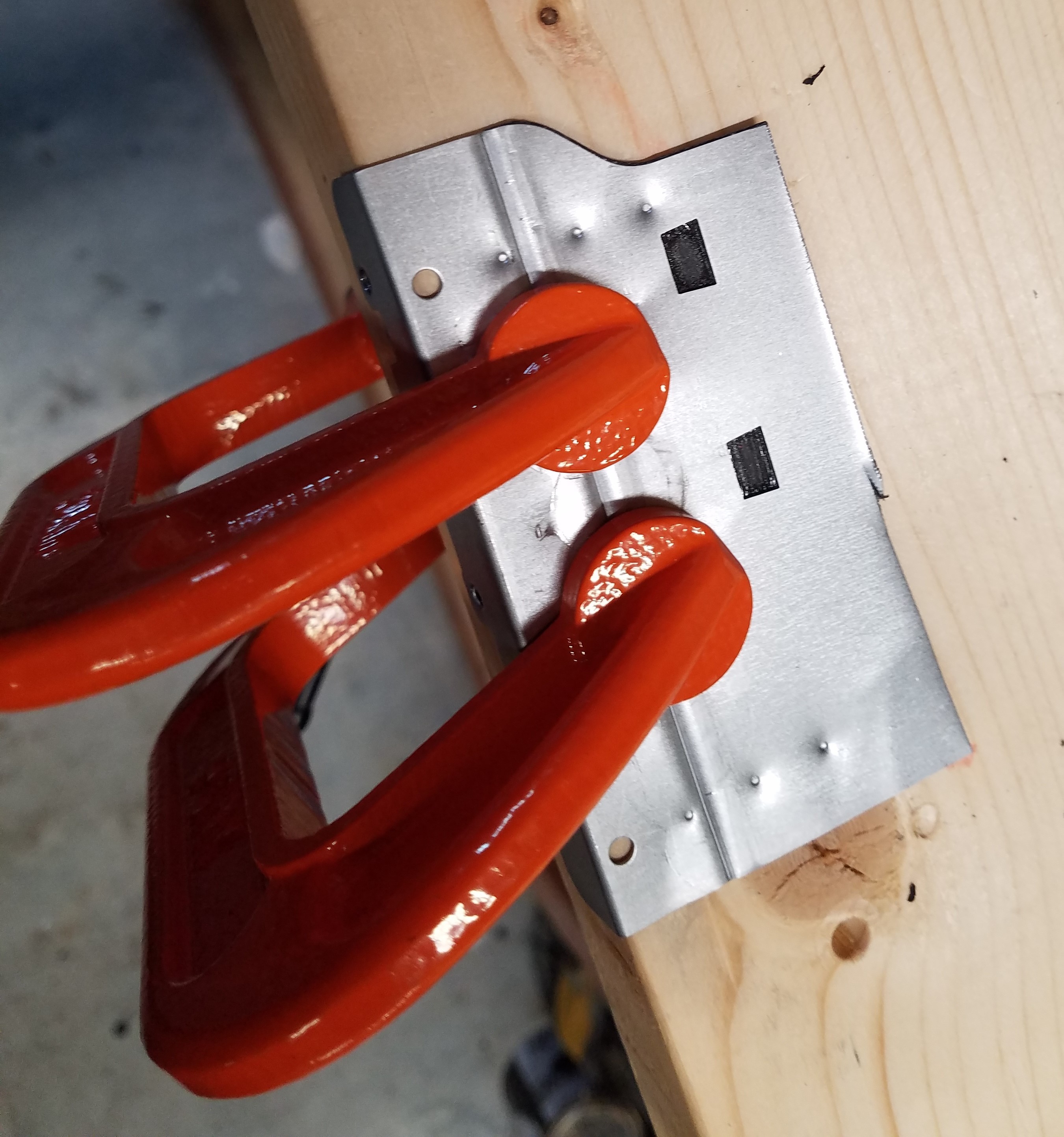
You can use a bench vise, or if you don't have one, use a couple of scrap pieces of wood and c-clamps to bend the bracket from a 'Z' shape to an 'L' shape. You'll have to flatten the bend creases as much as possible.
![]()
![]()
Here is what it should look like at this stage. Since the bracket already has a row of mounting holes for an SSD, it's now time to drill the remaining three rows of mounting holes for the other SSDs.
![]()
Download and print the SSD Drive Bracket Drill template. When you print, print at actual size. You'll see the four rows of mounting holes above the horizontal fold lines of the bracket. Align the bottom row of the template with the existing holes on the bracket and use your nail set to mark the remaining three rows of holes. These holes need to be sized to accept M3 screws, so you'll use your 1/8" drill bit.
![]()
When you've completed drilling the holes, you can deburr them by lightly hand twisting a 1/2" drill bit in each of the holes. Now, trim the height of each bracket half such that it will fit in the server chassis as below. Use a file to gently smooth the cut edges of the bracket. I used very short M3 screws to mount the drives.
![]()
-
4Building out the Super Micro Server Chassis
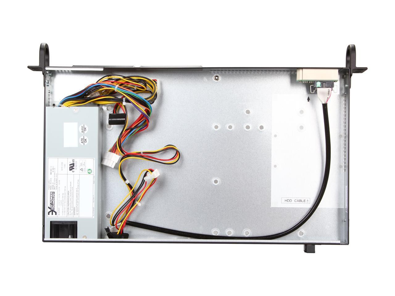
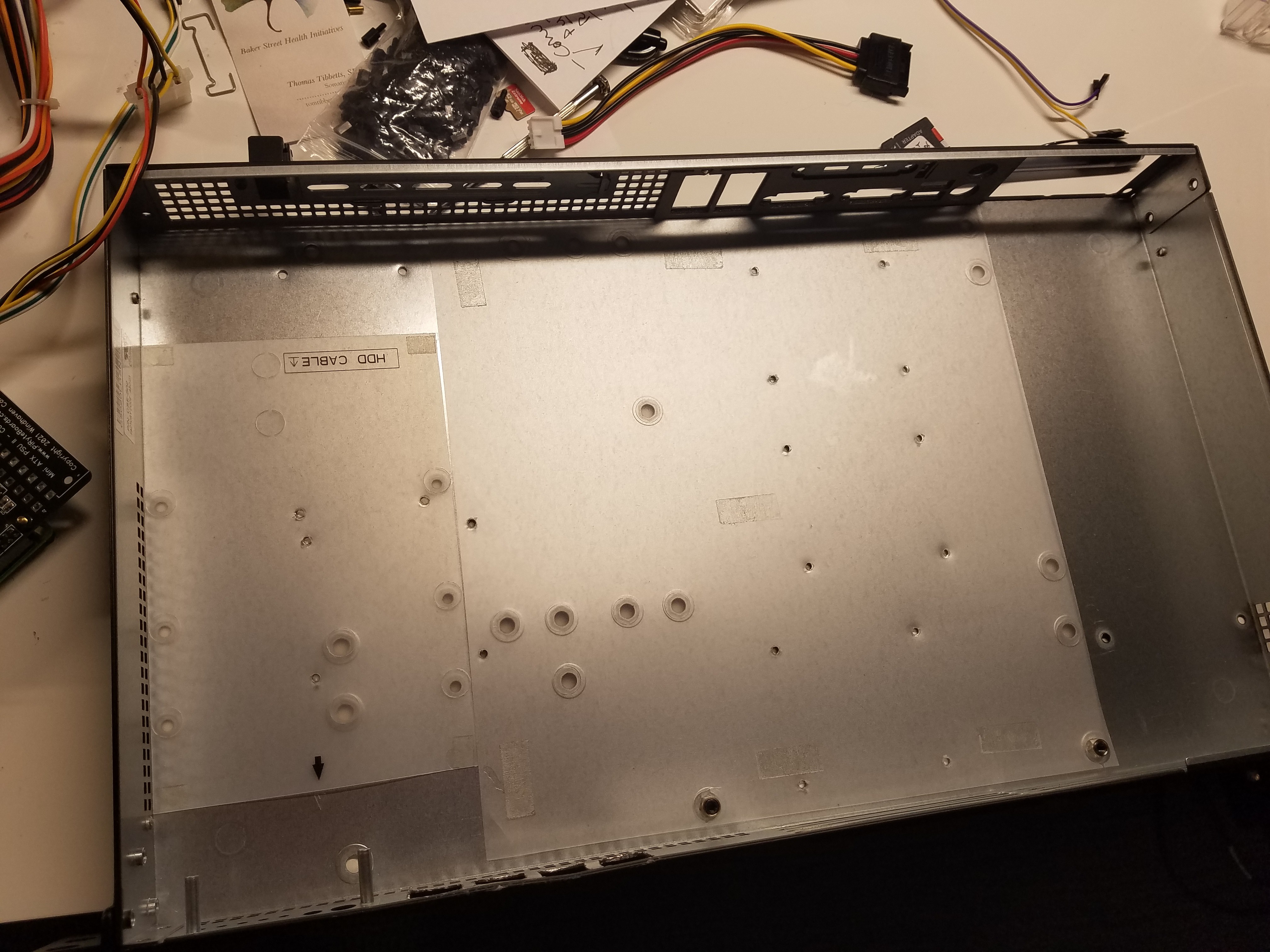
I had a severe size limitation to what I could fit as far as a server chassis into my existing home rack. The rack itself is 14 inches deep and I had only one spare 1U high space left I could use. So, the Super Micro chassis I selected was only ten inches deep in order to allow space behind the chassis for the power cord. This meant I could fit at most four Pis and one stack of SSDs. Space was tight but I managed to get everything I needed to fit. Below is a picture of the chassis from the factory.
I decided to keep the insulating plastic at the bottom of the chassis as an extra measure. Additionally, I kept the indicator lights and power switch on the front panel. The power switch is a momentary switch that I wired to the node zero Mini ATX PSU controller to power on/off/reboot the box. The lights (LEDs) are wired to all the Mini ATX PSUs to indicate power status.
![]()
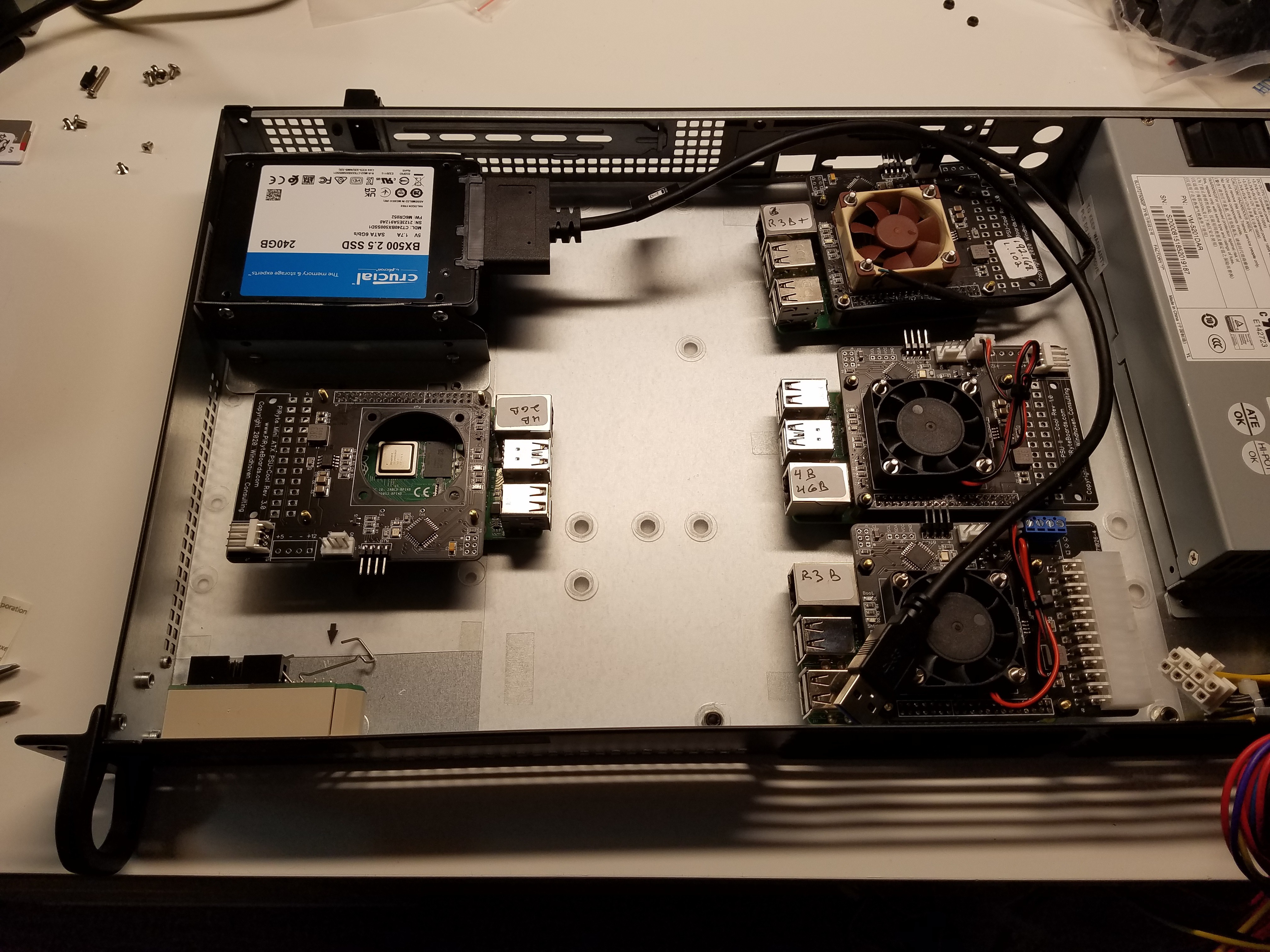
After several hours of noodling, I came up with a rough final layout of where all the Pis and SSDs would go as shown below. I designated the Pi 3B in the lower right hand corner as node zero. This would be the Pi whose Mini ATX PSU board would be powered by the PSU ATX connecter and would control the power up and down of the other Pis in the chassis.
In placing the subassemblies, I also needed to make sure all the cables for the SSDs, the ethernet patch cables and the power cables from the PSU had room to run. So, I allowed at least an inch between the backends of the Pis and surrounding areas for the power cables and a large central open area for the SSD and ethernet patch cables. Care must be taken not to strain the cables too much when making tight turns.
![]()
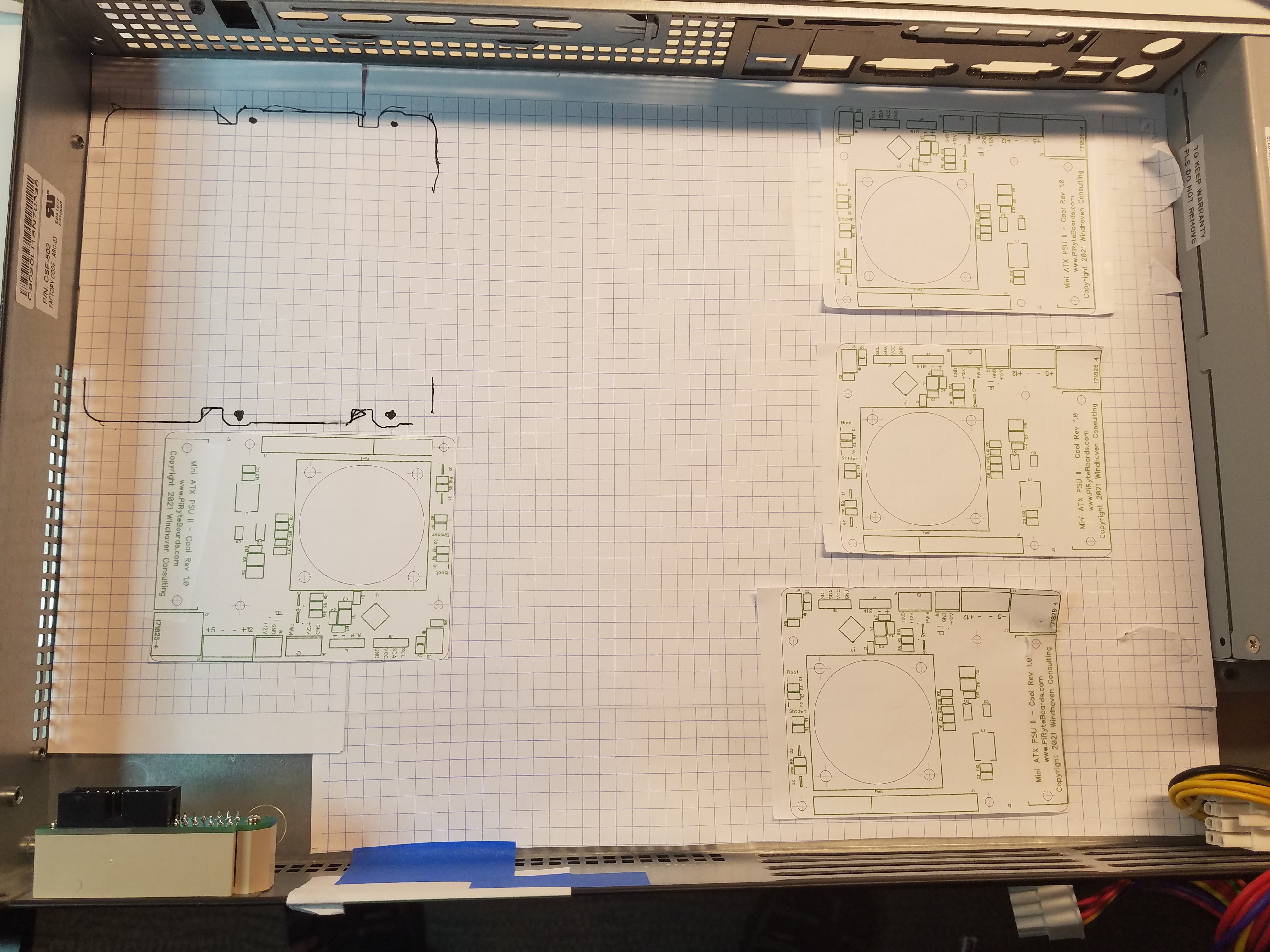
Once, I had decided on a rough layout it was time to mark the locations of the subassemblies. I downloaded some 5mm or 10 mm square graph paper and printed them out and taped them together to the bottom of the chassis. I then printed and placed the board outlines to the Mini ATX PSUs which, handily enough, have centers marked on the holes. I outlined the SSD bracket the old fashioned way :-).
![]()
Once I knew where all the holes would go, I used the thin point nail set and hammer and marked each hole location. I then removed the graph paper, the LED/Switch assembly and the PSU. I didn't want metal chips to go into any electronics. I left the plastic in place as I needed to have those drilled through. When I was done drilling, I removed the plastic and cleaned up all the metal shavings then replaced the plastic. I used a 7/64" drill bit for the 16 2.5mm mounting holes for the Pis and a 1/8" drill bit for the four 3mm mounting holes for the SSD mounting bracket. Then I deburred each of the holes the same way I did with the SSD bracket.
![]()
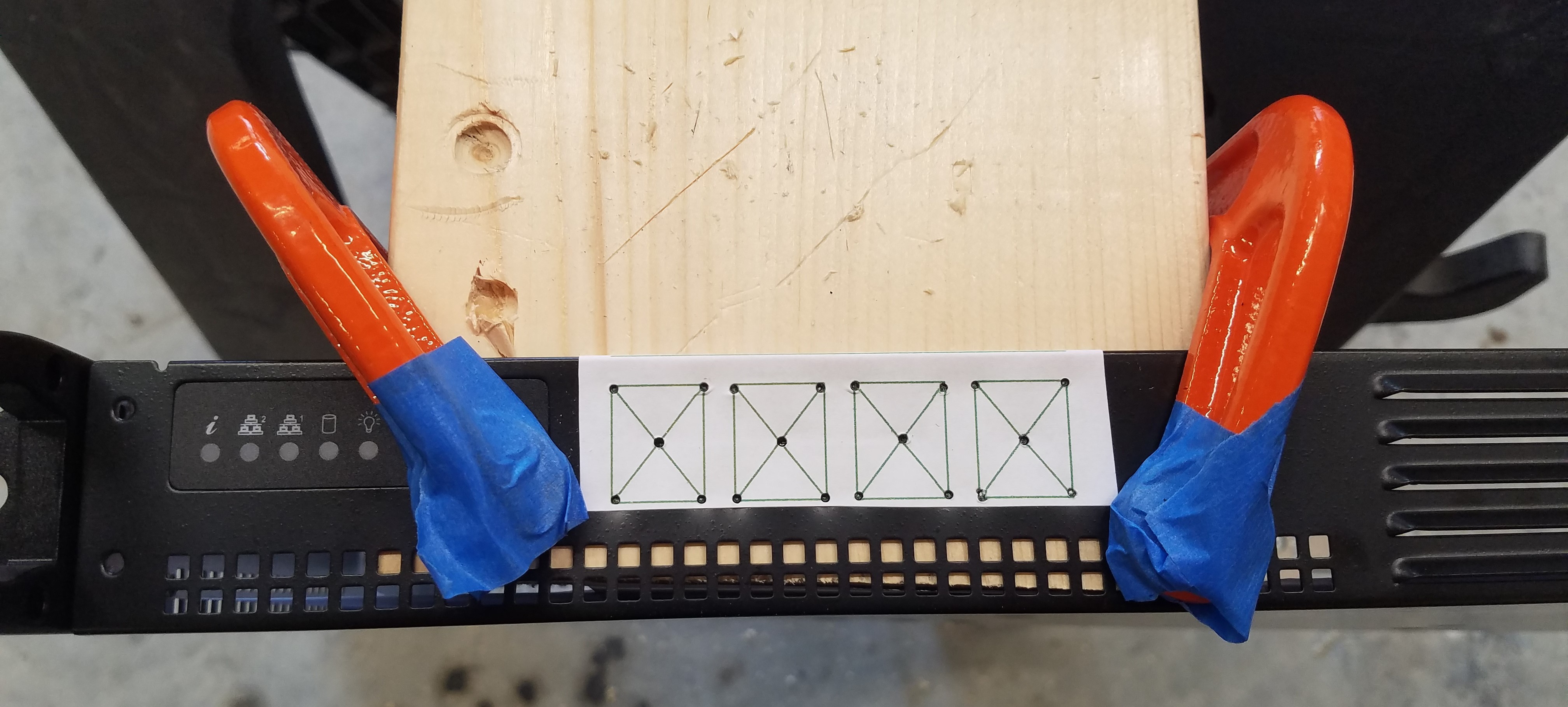
Next, I printed the template I created for marking the location of the Cat 5/6 couplers. I found that printing the template on large mailing label stock then cutting to size and sticking it to the front of the cabinet worked best. I used the narrow spacing between couplers to help facilitate cabling on the inside.
Below, you'll see that I used a scrap piece of 2 x 6 wood to support the metal of the cabinet for both marking the corners of the opening and where the pilot holes would be drilled. I used the 1/8" drill bit to drill the pilot holes where the center of the 'X's are.
![]()
Here are the pilot holes:
![]()
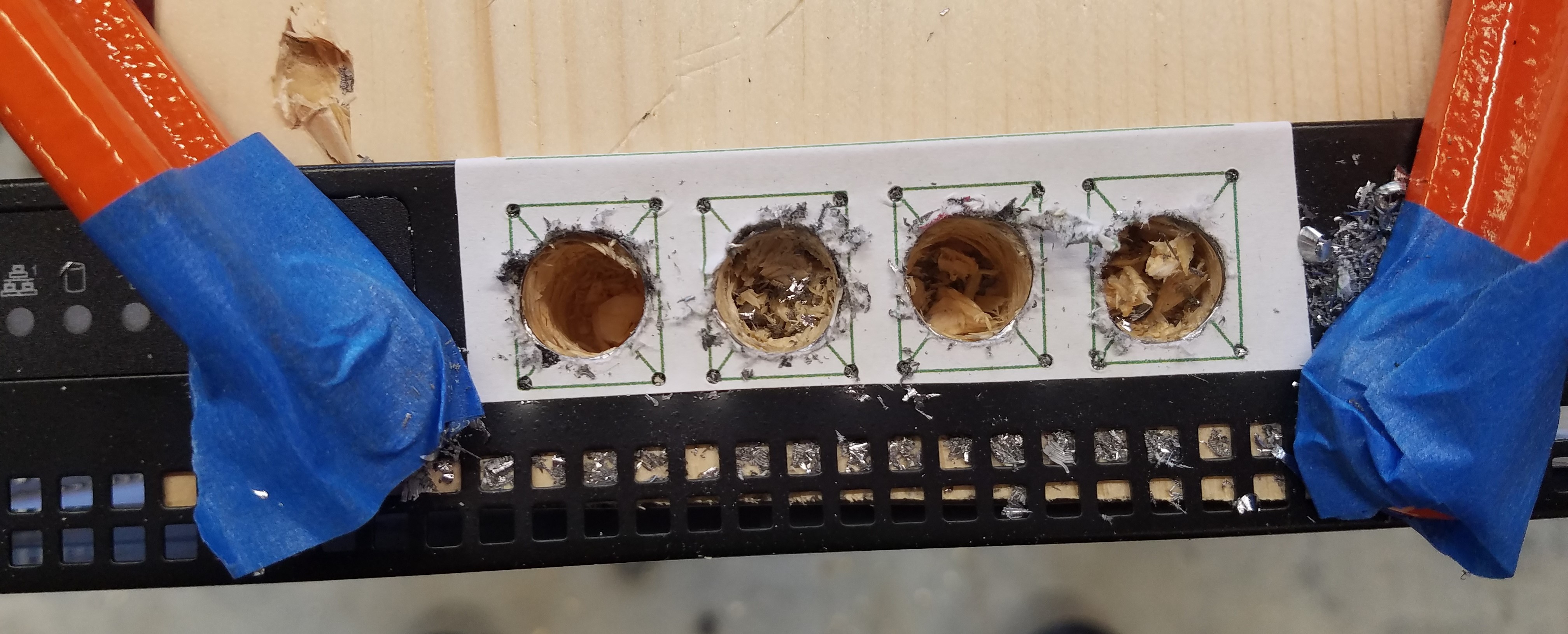
Here are the results of using a 1/2" drill. These larger holes will allow me to somehow nibble away the sides of the square holes for the couplers. Now you see why I use a backing board :-).
![]()
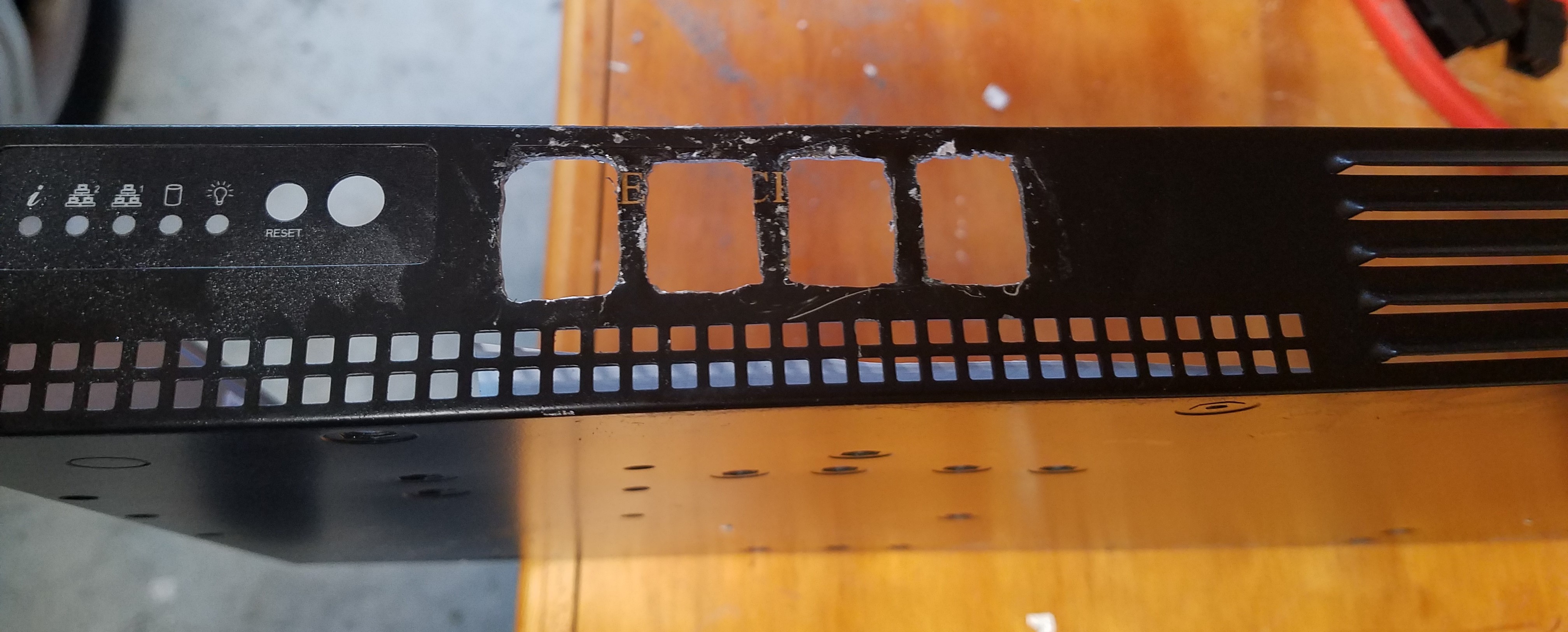
And, after much nibbling with various tools (I experimented a lot) and filing the edges I got the holes to a point where I could insert the couplers. It's not pretty but it works. If I do this again, I will find a better way :-)
![]()
Finally, here is what it looks like with the couplers installed. I used prodigious amounts of hot melt glue on the inside of the cabinet to make sure these puppies weren't going anywhere.
![]()
-
5Installing the Pis
Now that I had all the mounting holes drilled, the Cat 5/6 couplers installed, I cleaned out any and all metal shavings, and replaced the plastic liners at the bottom of the chassis. Now comes the fun part! Putting everything back together again.
Now, anything worth doing is worth doing over and over and over again. What seem like simple steps in the following were actually performed multiple times as I figured things out. I'm hoping that these steps will short cut you somewhat.
First thing is to attach the Startech cables to the SSDs and mount the SSDs in their bracket. Then I downloaded the latest 64 bit lite version of Raspi OS to my Windows machine which in this case was 2021-05-07-raspios-buster-arm64-lite.zip
For each SSD, I performed the following steps:
- I configured and formatted the drive on my Windows machine so that Windows would recognize it.
- I used the Raspi imager to image the previously download image to each drive.
- Once the drive is imaged, it seemed that it became unmounted from Windows. So, I unplugged drive then plugged it back in. Windows was then able to see it.
- I then navigated to the /boot folder of the SSD and created a file named 'ssh' there. I used a text editor, in this case Notepad++ to add an empty line to the file then saved it. This empty file tells the Linux OS that you want to SSH into that computer from a remote computer.
Next, enable each Pi to boot from a USB drive instead of the SD card. You may want to do this before mounting the Mini ATX PSU:
- Pi 4 - image an SD card using the Raspi imager under Boot Maint. I chose to have it try booting from an SD card before giving up and booting from the SSD. You may want to do the opposite to save a bit of boot time. I think Pi 4s do this naturally, but it bears verifying
- Pi 3B and 3B+ are configured differently. Please refer to: USB Mass Boot Modes for Raspberry Pi
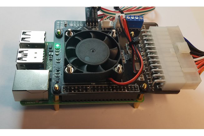
Now, assemble the Raspberry Pi/Mini ATX PSU subassemblies, remembering to use the plastic standoffs to support the Pis. The final assembly should look something like this:
![]()
I feel the assembly instructions for the Mini ATX PSU are pretty complete so I won't repeat them here. You will find them up on the Tindie store for the Mini ATX PSU II under 'Datasheet'. Assemble the parts, but don't install any of the scripts yet.
Mount each Pi subassembly into the chassis, connect the SSD into the USB slot and connect the appropriate power connector to the Mini ATX PSU board. You may wish to only power up one subassembly at a time until your comfortable with the following installation process for each Pi:
- Connect the Pi to a router for installation purposes. You may also want to connect a keyboard, mouse and monitor to the Pi to make things easier at this point. Power up the Pi. You should be booting from the SSD at this point, and the file system should expand to fill the entire drive
- Update the OS to the latest version
- Sudo into raspi-config and change the password. Make sure you also enable I2C. The Mini ATX PSU requires this and explains it in its manual.
- While you're in raspi-config, change the hostname of the Pi. I used 'Clusterpi-nodex' as an example.
- Import the I2C tools and import the appropriate Python libraries.
- Install the Mini ATX PSU installation script for startup/shutdown monitoring. Additionally, install the fan control script. This script adjusts the speed of the fan on the Mini ATX PSU depending on the temperature of the Raspberry Pi.
- Set the static IP address for the Raspberry Pi.
- Reboot and see if everything is working correctly.
-
6Final Assembly
Once I've verified that all the Pis boot and run and that I can now SSH into them, it's time to batten down the hatches.
First, I figure out the final routing of the power and SSD USB cables. Zip ties on the power cables help to keep things neat.
Next, I plug the ethernet patch cords from each of the Pis into the couplers. I configured mine so that from left to right, I have Node 0, Node 1, Node 2, Node 3.
Finally, I wire up the front panel momentary power switch and indicator LEDs to the Pis. The momentary switch is wired to Node 0 while the indicator LEDs are wired to each Pi to indicate power status. I had to use a multimeter to ping each pin on the ribbon cable. Fortunately, my multimeter has a diode tester that illuminates LEDs with a small amount of voltage when the polarity is correct. Here are the pin assignments for the Super Micro ribbon cable:
Description Pin Number Pin Number Description On/off switch 1 2 On/off switch return Reset switch (not used) 3 4 Reset switch (not used) N/C 5 6 N/C LED 1 + (Red) 7 8 LED 1 - (Red) LED 2 + (Green) 9 10 LED 2 - (Green) LED 3 + (Green) 11 12 LED 3 - (Green) LED 4 + (Yellow) 13 14 LED 4 - (Yellow) LED 5 + (Green) 15 16 LED 5 - (Green) For each wire on the ribbon cable I used, I spliced the female end of a breadboard jumper to the wire. I color coded the wires for positive (red) and negative (black) polarity for the LEDs. I used heat shrink to insulate any bare wires as shown below. I then connected the wires to the appropriate power LED connectors on each of the Mini ATX PSUs.
![]()
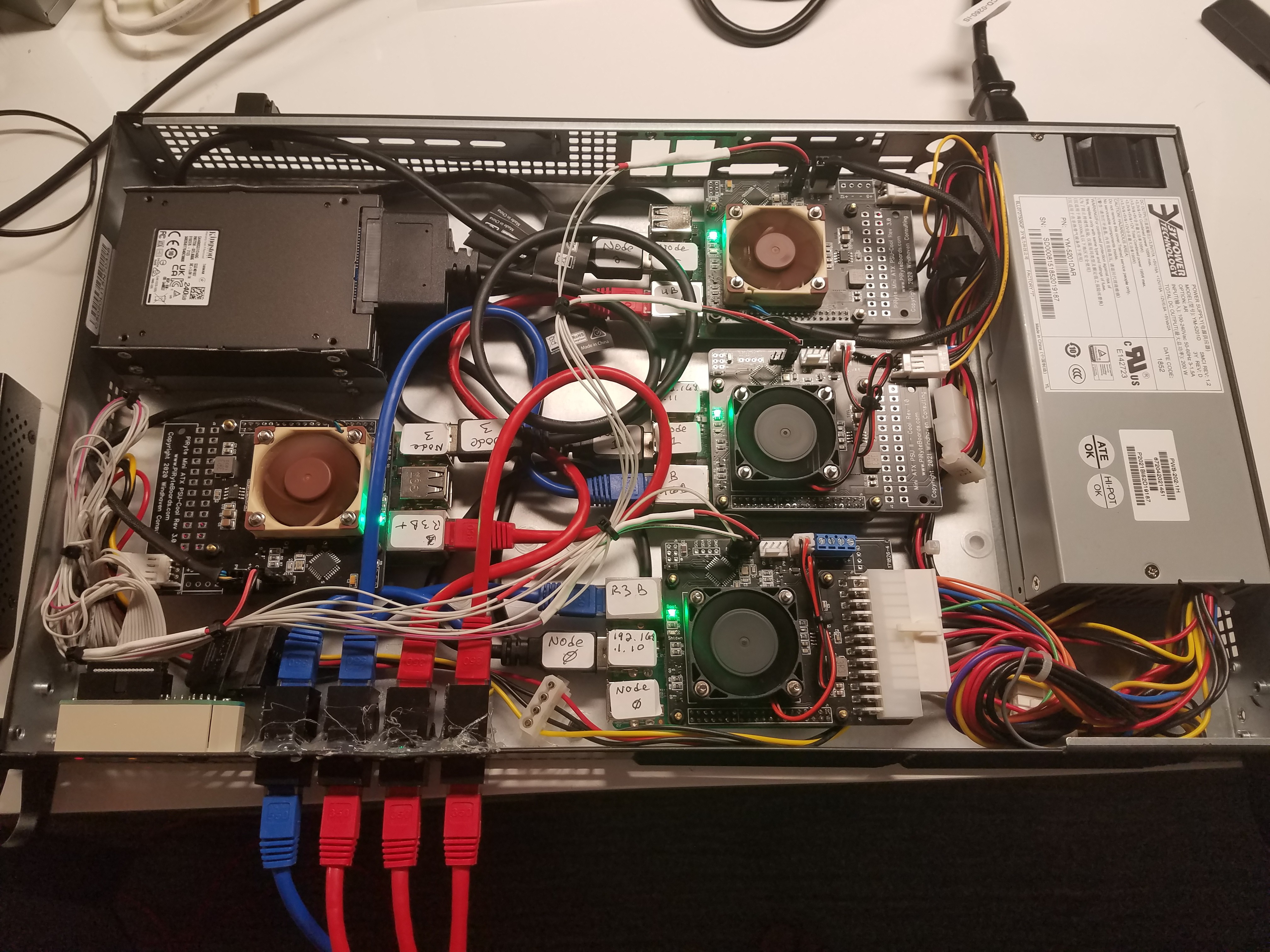
When you're all done, you should have something that looks like this:
![]()
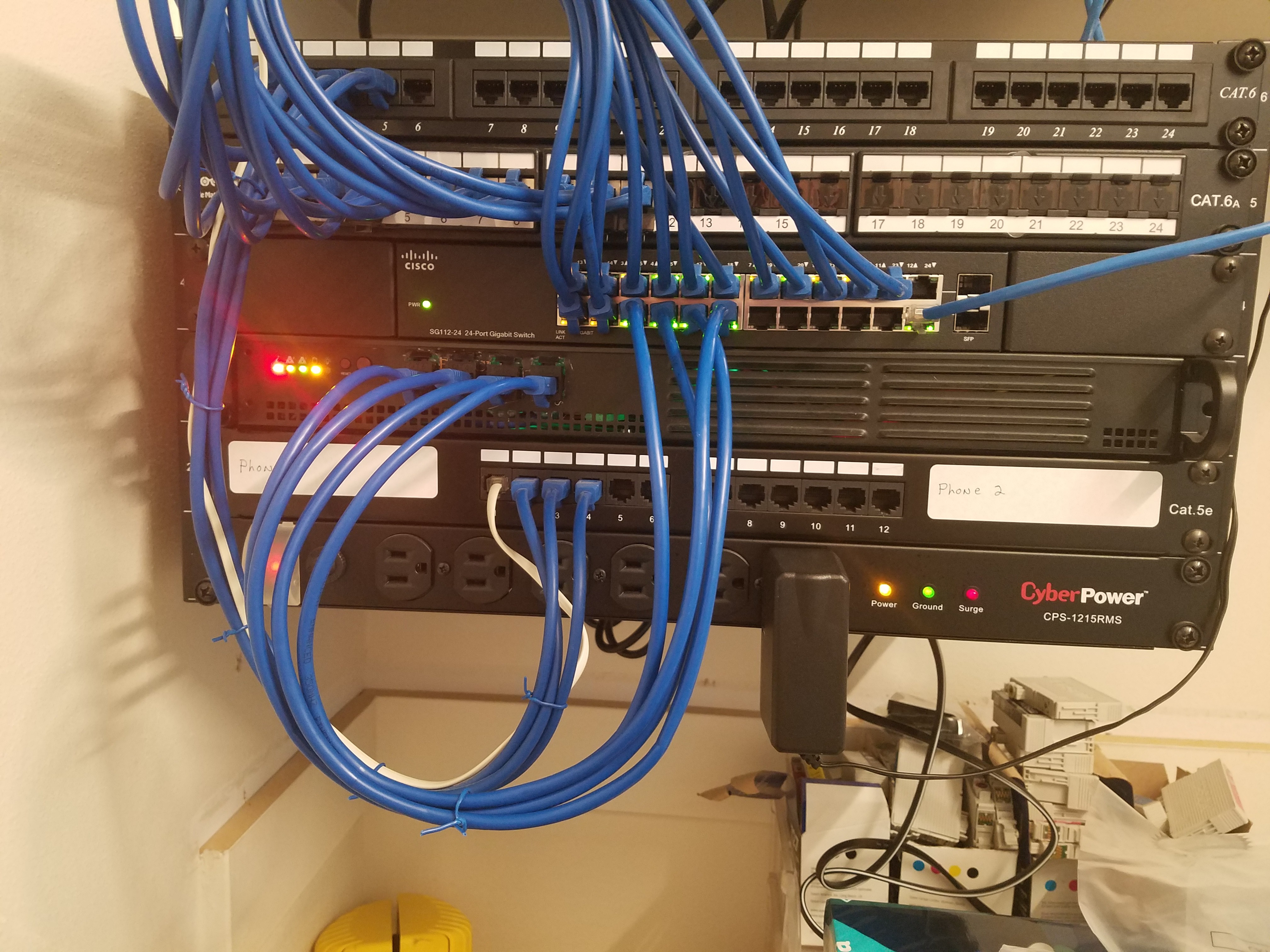
And, now it's in its happy place in my rack:
![]()
Happily running nothing in particular:
![]()
-
7Project Retrospective, Lessons Learned
By and large, I'm very happy with this project. Plus, it was very fun and creative for me. It will accomplish all of my immediate goals in that I can now play around with Kubernetes and whatever else strikes my fancy.
Having said this, I did wish I had a 3D printer for making the SSD bracket. I like clean installations and a 3D printed bracket would have helped. However, the down side is that the bracket I made cave man style does act as a heat sink for the drives.
I wish I had learned about the round Cat 5/6 couplers earlier. It would have saved a lot of work in making the holes for the couplers in the chassis and made for a cleaner look: 5PCS Ethernet LAN Cable Connector. It's much easier to drill a round hole than to make a square one.
Cluster Pi - Yet Another Pi Cluster Project
A four Pi cluster built into a 1U server chassis


Discussions
Become a Hackaday.io Member
Create an account to leave a comment. Already have an account? Log In.