kevarek
See project log below for all design steps - schematic, simulation, build and validation.
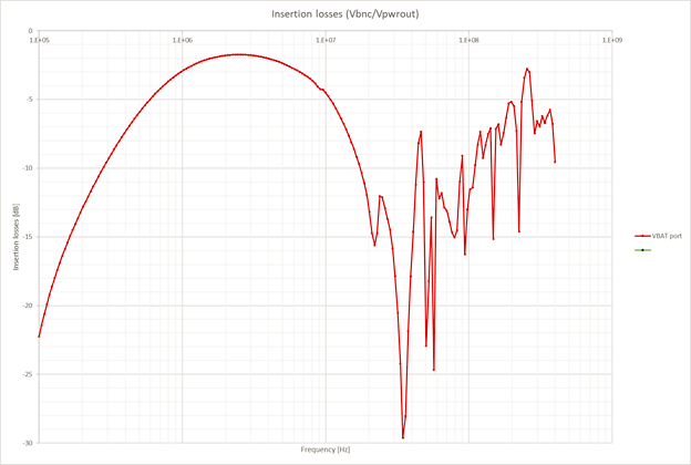
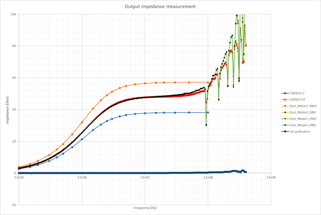
Building 5uH CISPR25 LISN seems like very simple task but evil is in the detail. Without careful evaluation of circuit and housing parasitic properties, it wont pass standard's requirement for output impedance. Furthermore, its unstable insertion losses might render it completely useless.
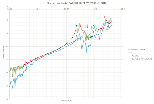
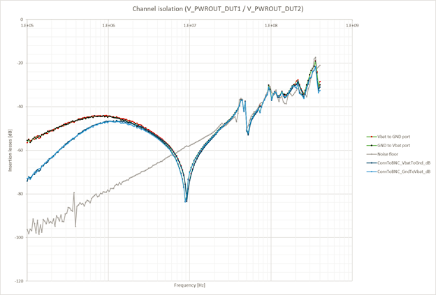
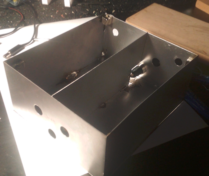
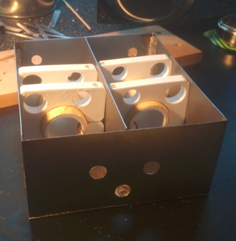
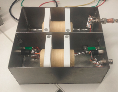
Hobbyists tent to stuff two channels into single box (like in CISPR-15 50uH LISN used for home appliances), which brings additional issue - channel separation aka cross-talk.
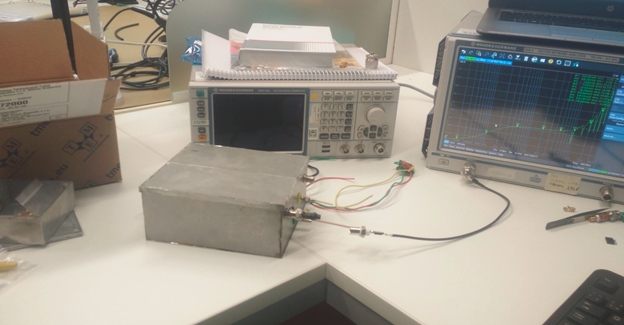
It is not really possible to evaluate the build quality without access to very expensive instruments (Spectrum analyzer with tracking generator or vector network analyzer).
To get true feeling how hard the design and build might be please read first: https://www.eevblog.com/forum/projects/5uh-lisn-for-spectrum-analyzer-emcemi-work/ https://www.eevblog.com/forum/projects/5uh-aerospace-lisn-how-dumb-would-i-be-to-throw-one-together/ https://www.eevblog.com/forum/rf-microwave/50uh-and-250uh-inductor-design-for-lisn/
Also watch amazing video series from FesZ:
Part 1: https://youtu.be/OEvkRW5vZNA Part 2: https://youtu.be/nq-IhHbZdD0 Part 3: https://youtu.be/M_ab0Oz2ypI
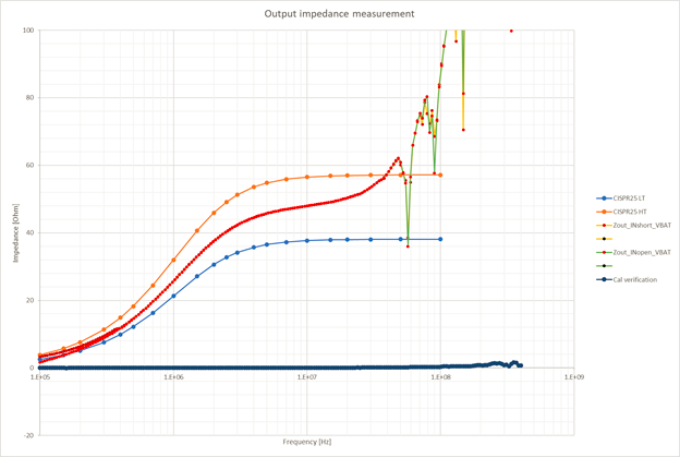
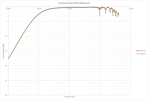
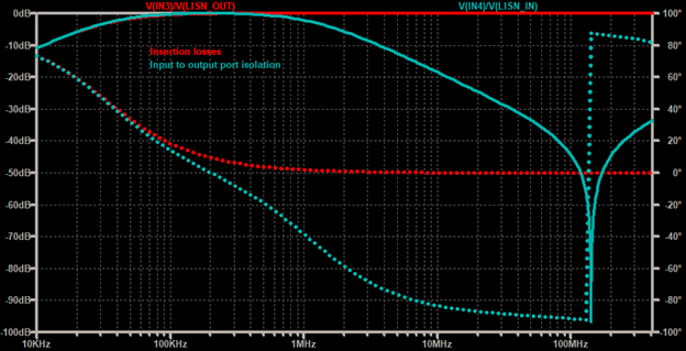
Aim of this project was to have final working product for daily usage and therefore full testing and its validation across frequencies up to 100MHz is as important as the assembly itself.
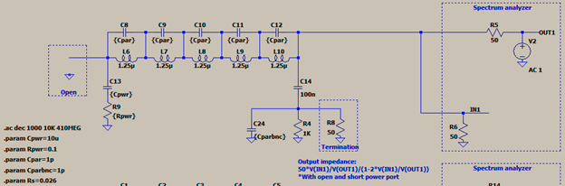
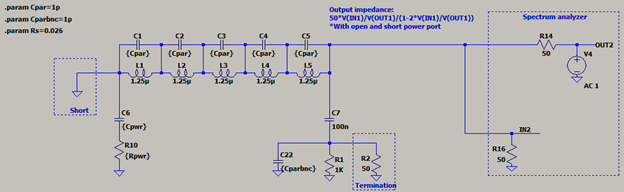
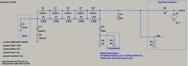
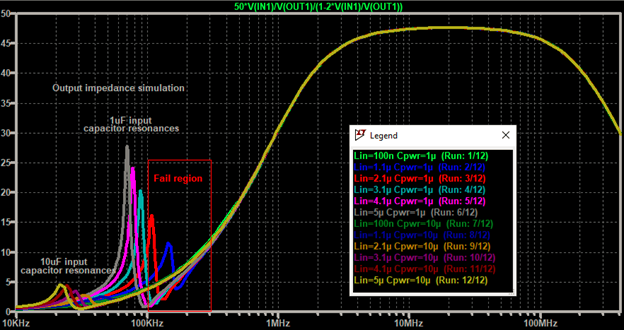
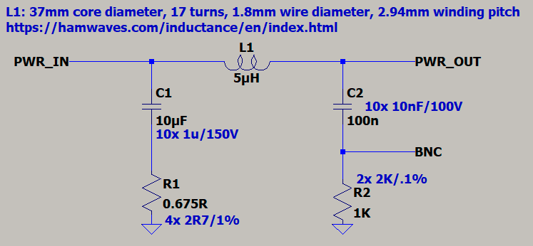
Schematic is deceptively simple. Basically CISPR25 circuit with exception of input capacitor capacitance which is 10uF ceramic capacitor in series with resistance 0.5 to 1 Ohm instead of just 1uF capacitor. This is helps to prevent "output impedance out of limits" issue when wiring inductance between power supply and LISN is above 0.1uH. This issue and its solution has been proposed somewhere in the mentioned EEVblog forum threads.
All capacitors consist from multiple units of same capacitance and package to enhance their high frequency properties (less parasitic equivalent series inductance, prevention of resonances and anti-resonances of the capacitors).
R1 actually consists from four 0805 resistors in parallel to achieve above 1W power dissipation rating. Its final exact resistance does not matter while in range from 0.5 to 1 Ohm.
All components (except L1) should be surface mount type to lower their parasitic properties impact to high frequency response.
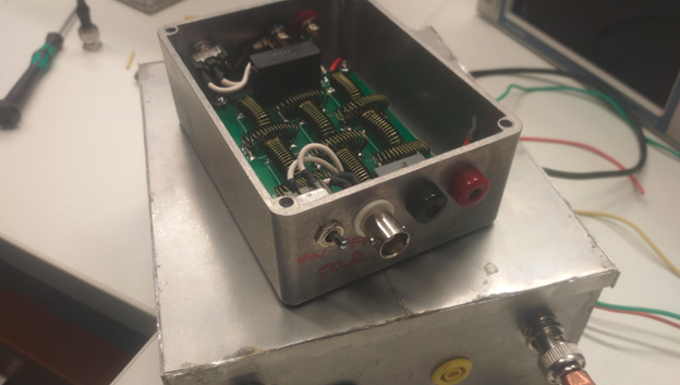
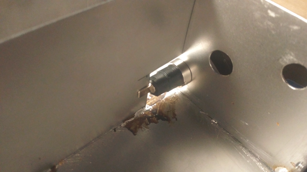
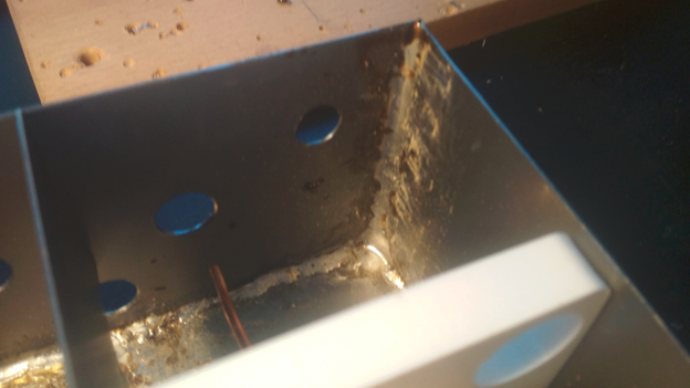
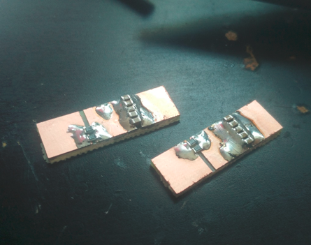
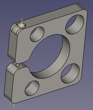
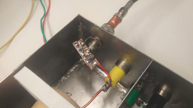
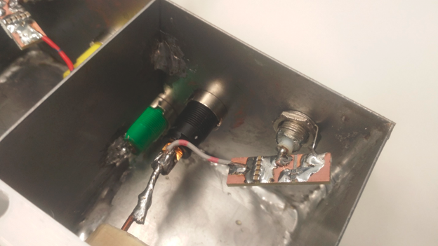
Detail of output side PCB. Every centimeter of wire adds significant amount of undesired behavior above ~50MHz.
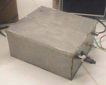
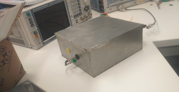
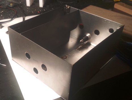
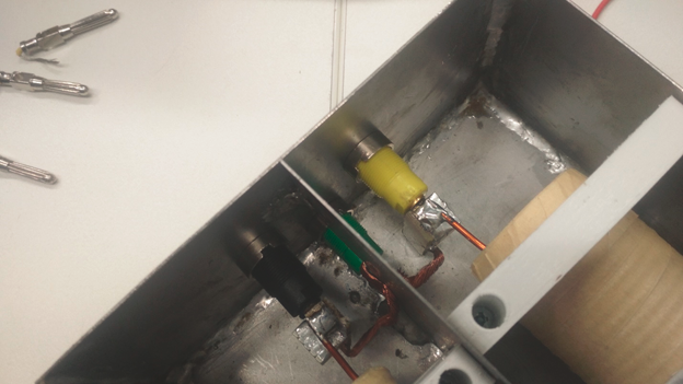
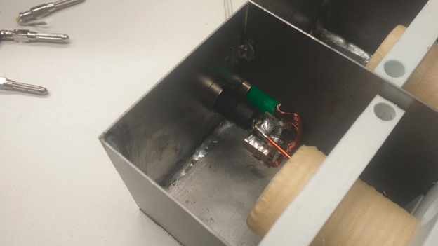
Final product ready to be tested