 kevarek
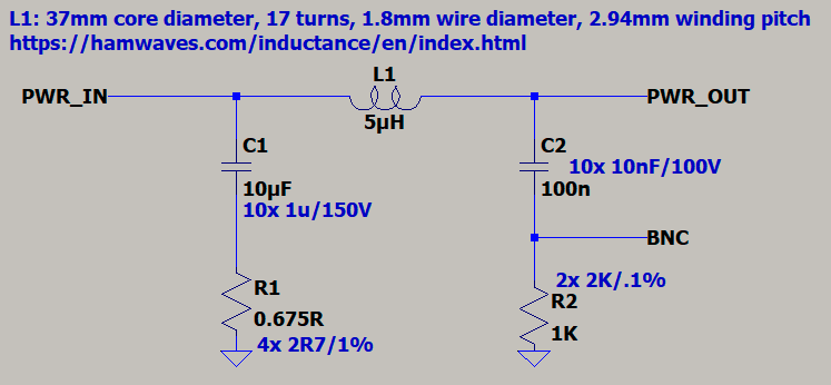
Schematic is deceptively simple. Basically CISPR25 circuit with exception of input capacitor capacitance which is 10uF ceramic capacitor in series with resistance 0.5 to 1 Ohm instead of just 1uF capacitor. This is helps to prevent "output impedance out of limits" issue when wiring inductance between power supply and LISN is above 0.1uH. This issue and its solution has been proposed somewhere in the mentioned EEVblog forum threads.
All capacitors consist from multiple units of same capacitance and package to enhance their high frequency properties (less parasitic equivalent series inductance, prevention of resonances and anti-resonances of the capacitors).
R1 actually consists from four 0805 resistors in parallel to achieve above 1W power dissipation rating. Its final exact resistance does not matter while in range from 0.5 to 1 Ohm.
All components (except L1) should be surface mount type to lower their parasitic properties impact to high frequency response.
 I decided not to implement standard 10dB attenuator to keep it simple, but plan is to build is as external unit later. This also helps to keep the validation and root cause analysis of possible issues simpler.
Discussions
Become a Hackaday.io Member
Create an account to leave a comment. Already have an account? Log In.