Typically, four basic simulations are performed. This is helpful to understand influence of parasitic properties of electronic components and also helps to identify schematic nodes sensitive to parasitic capacitance to housing etc.
Output impedance simulation with power input floating.
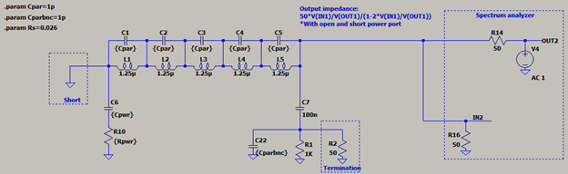
Output impedance simulation with power input shorted to ground.
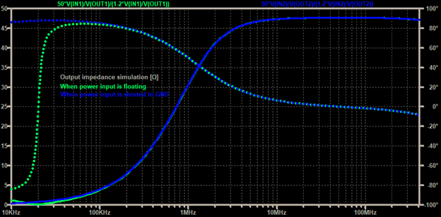
These simulations help to verify that LISN complies to CISPR-25 limits to impedance magnitude and phase angle. Both simulation results are in chart below.
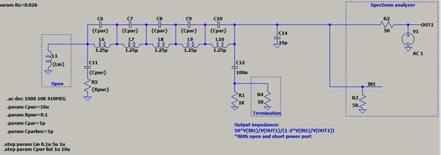
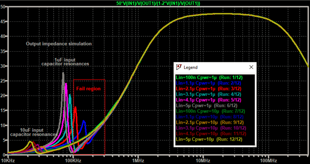
Output impedance simulation with excessive harness inductance from power supply to LISN
There is one more output impedance simulation to be done which helps to understand 1uF input capacitor issue and why 10uF or higher capacitance in series with damping resistor is used. In case there is substantial wiring inductance between power supply and LISN input ports it could resonate with input capacitor. It is important that this resonance won’t affect output impedance being within CISPR-25 limits. Placing 10uF helps to push resonance much below 100kHz. If measurement down to 10kHz is required it is possible to increase the capacitance even more.
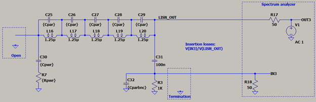
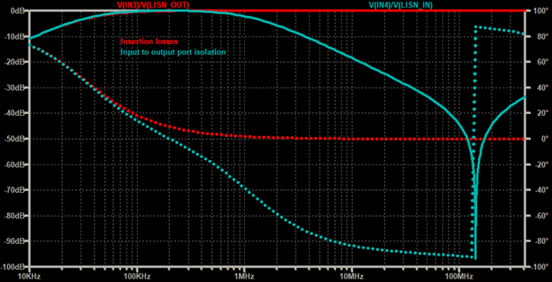
Insertion losses simulation
Insertion losses represent how much of signal generated by DUT (device under test) on LISN power output port is transmitted to signal output BNC connector. Measurement taken by spectral analyzer on this port needs to be compensated by this result before comparison with emission limits.
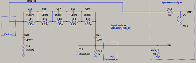
Input to output isolation simulation
This represents how much noise from power supply can pass through LISN power input into power output and affect the measurement. Dominant resonance at 150MHz is caused by parasitic inter-winding capacitance and needs to be kept above measurement range.
It is worth playing with simulation parameters:
inter-winding capacitance Cpar of inductor L1 which causes decrease of output impedance in higher frequencies and inductor self-resonance which deteriorates input to output isolation.
parasitic capacitance Cparbnc of signal output to GND which causes steep decrease of output impedance above 100MHz and also shifts a bit inductor L1 resonance frequency.
 kevarek
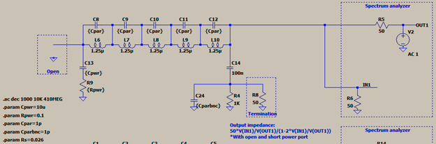
Discussions
Become a Hackaday.io Member
Create an account to leave a comment. Already have an account? Log In.