 Bin Sun
-
1Prepare the Mouse
I modified the computer mouse with two different designs. The simple ways is to remove the original micro switch for the left and right mouse button, and use two M3 stainless steel screw as capacitive touch sensor electrodes at corresponding locations. This should work for most of the people. I also created another version that uses 3mm LED with metallic (copper) socket as touch sensor electrodes with LED as visual touch confirmation. This latter design allows one finger to control both left and right button with visual confirmation, and is more suitable with the consideration for the ALS patients. You can decide which one works for you.
Dell MS-116t wired mouse is chosen in this project as example because I happen to have several of them laying around. They are inexpensive, easy to work with, and have good quality and performance, and compatible with Windows PC, Apple iMac as well as Chromebook. It is based on PixArt PAW3515DB chip which can be found inside many of the computer mice. The same concept can be applied to variety of the computer mouse with minor modification to the wiring.

Capacitive Touch Mouse Designs Step 1
The first step is to dissemble the mouse by removing the bottom Teflon pads with a knife or small screwdriver, exposing the 2 Philips head screws underneath.
Step 2
Once the screws are removed, the top and bottom of the mouse will separate easily. Remove the printed circuit board and remove the left and right mouse button micro switches using disordering iron.
Step 3
Drill holes at appropriate locations at the top mouse shell. The top mouse shell consists of two parts and can be separated. I will first drill a small pilot hole with two parts connected, then separately to make sure that I don't damage the top surface. Additional washers can be added between the top and bottom to make the mouse completely non-clickable.

-
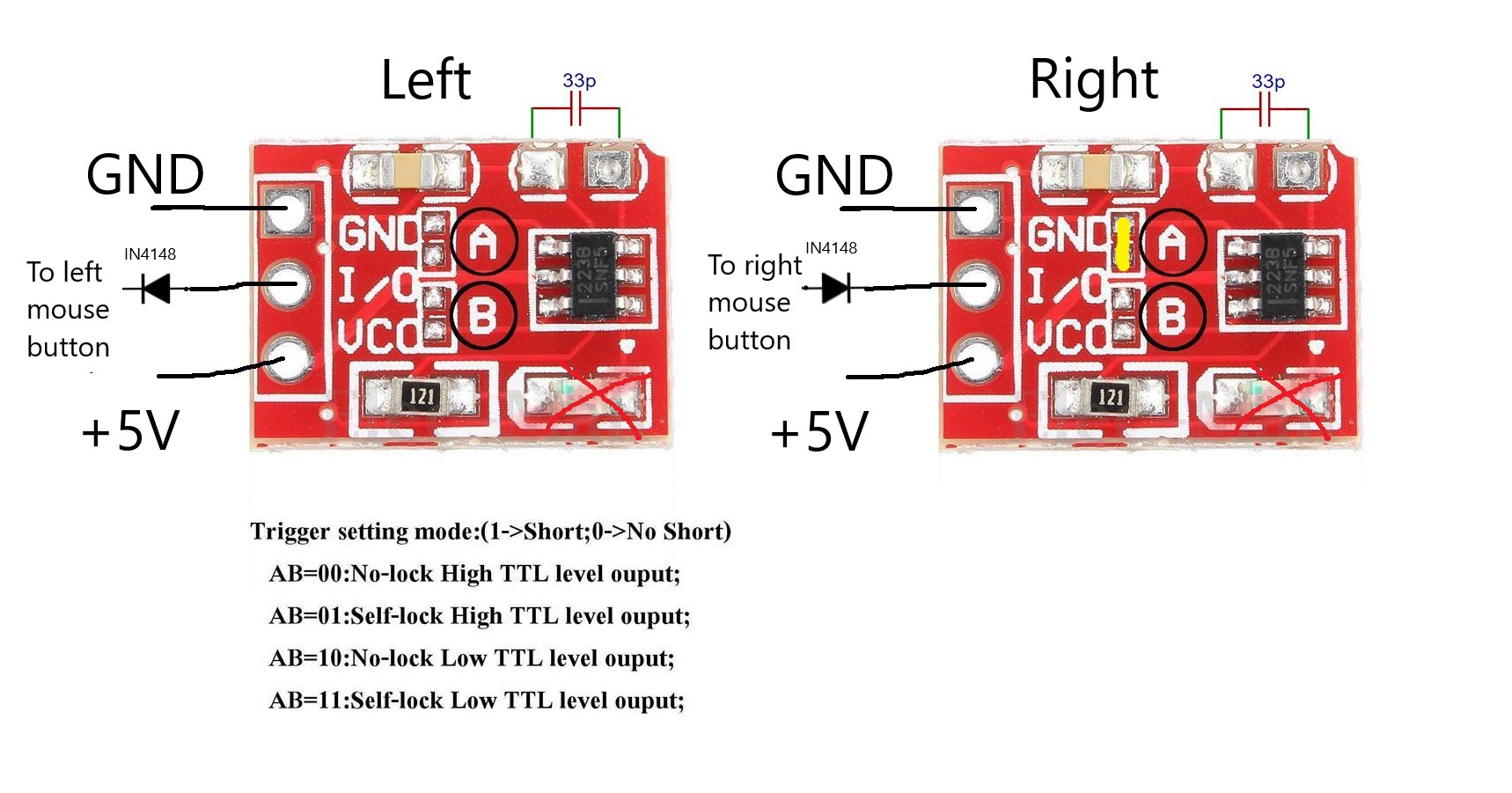
2Modify the TTP223 Module
I purchased the TTP223 Module from Amazon, which needs to be modified to fit our needs. First a 30-33 pF capacitor needs to be added to the empty pad on the board to get appropriate touch sensitivity. Also by default these modules are in toggle mode with output signal active-high. According to the mouse circuit diagram, the right mouse button switch is active-low, therefore we need to make the TTP223 module output goes to the right mouse button active-low. This can simply be done by bridging the pads marked A on the module (AB=10). Also remove the SMD LEDs on the modules if optional external LEDs are going to be used.
![]()
-
3Wiring and Assembly
First, connect the touch electrodes to the TTP223 modules by soldering a wire from the module to the base of the electrodes. A copper washer should be used if the M3 stainless screw is used as electrode, since the stainless steel can not be soldered.
We then need to connect the TTP223 modules to the +5V power and ground as well as the left and right mouse buttons on the computer mouse PCB. Below is complete wiring diagram with the optional touch button LEDs included, as well as the location of connection points to the micro switches pads on the PCB. Two IN4148 diodes are added between the outputs of the TTP223 modules and the button inputs on the mouse PCB to eliminate the false signal.

Schematics 
PCB Connection Points 
Finished Touch Sensor Module -
4Test and Use
The mouse functions can be tested using Online Mouse Test.
Capacitive Touch Button Computer Mouse Hack
Mouse modified with capacitive touch button not only helps those with limited mobility (such as ALS), but also makes the mouse click silent


Discussions
Become a Hackaday.io Member
Create an account to leave a comment. Already have an account? Log In.