 W. Jason Altice
-
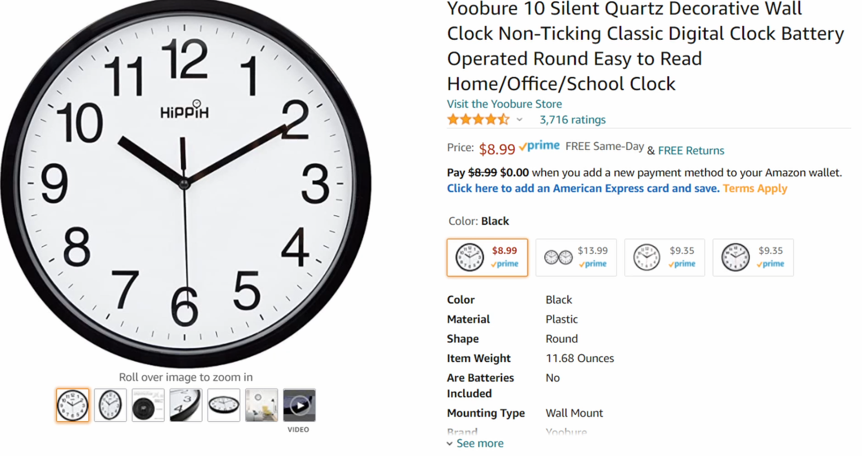
1Pick out a clock
To start, find a clock you like on Amazon or where ever. I chose this basic clock because it was really in expensive and good enough size to house all of the components I would need.
-
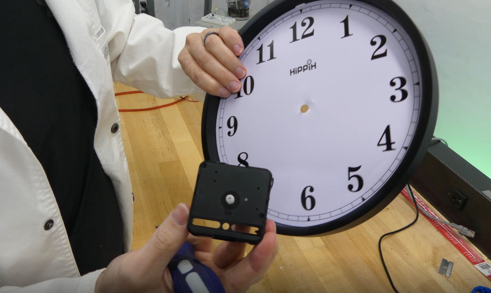
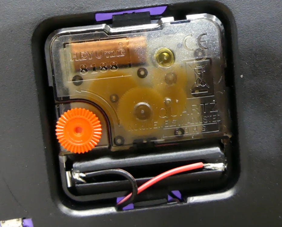
2Take the clock apart
This is the easy step, just take the clock all apart to the base platform. Remove the face, hands, and motor.
-
3Print out a new face.
I used my 3D printer to make the face but you don't have to. You could just print out something on your printer. But, because I used my 3D printer with a small bed, the face I printed didn't cover the entire clock. This turned out to be OK because I had also printed out inside trim pieces to offset the face from the back of the clock.
If you do use a 3D printer, this will have to be a vector graphic.
-
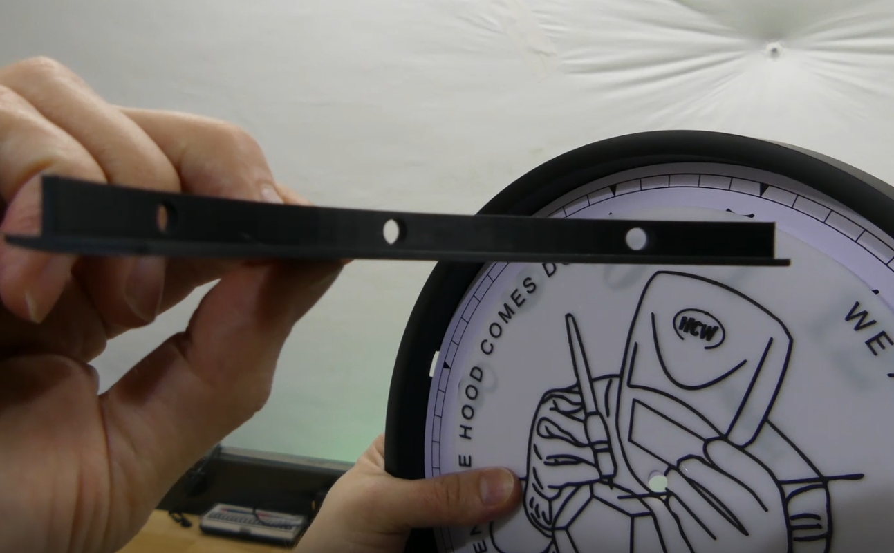
4Print out the inside trim pieces
These trim pieces allow the face to be offset from the clock. I had to do this because I was adding a display, but I could also just have cut out the back of the clock. Do whatever fits your needs, this is just the road I took. I think I will try cutting out the back of the clock next time.
-
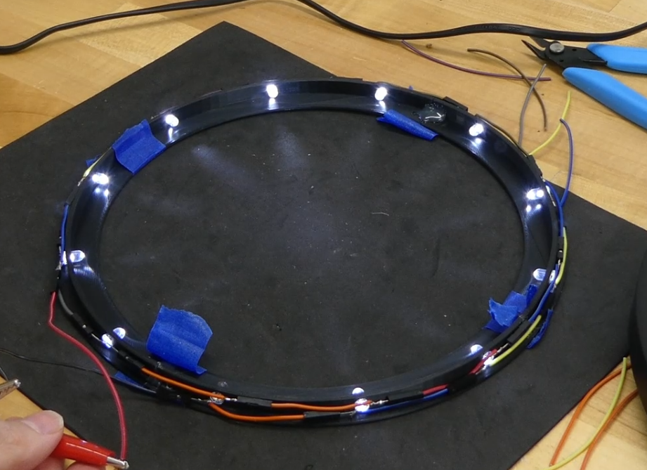
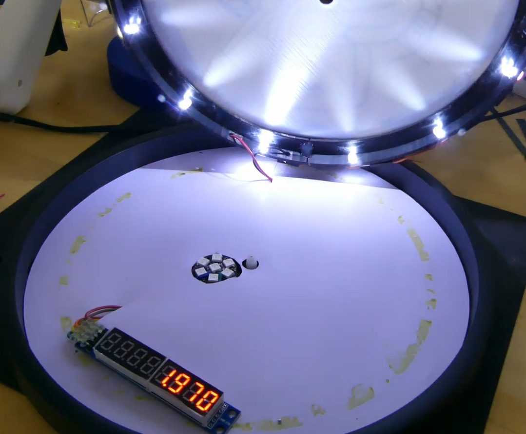
5Add backlights to the inside trim pieces
The trim pieces have holes for 3mm LEDs. This will provide back lighting. You can use any form of backlighting you'd like, I just have a lot of LEDs to use.
-
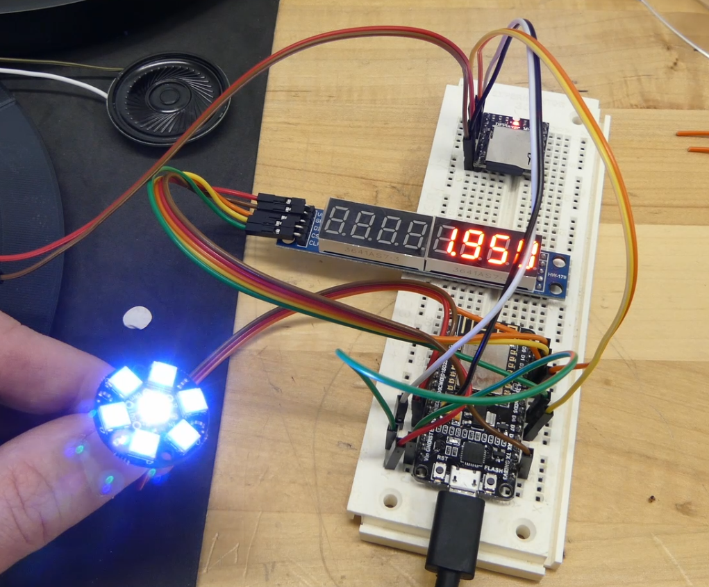
6Test the components
I typically use a bread board for smaller project to ensure things are working before I set everything into place. This provides an easy way to test and debug any issues. It also gives you assurance that it worked before installing it into the clock, so if anything broke it was during the installation. The wire diagram and code are on GitHub.
https://github.com/CodeMakesItGo/ThemedClock
-
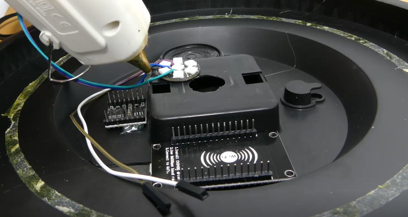
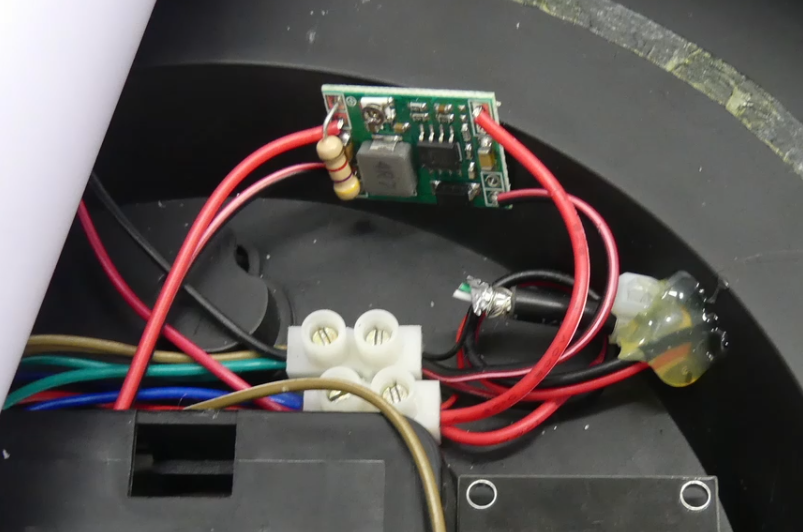
7Install components into clock
After everything is working on the bread board it is time to transfer them into the clock. The only component that I really cared about positioning correctly was the DF Player because I wanted access the the SD mini card to change the sounds if needed.
-
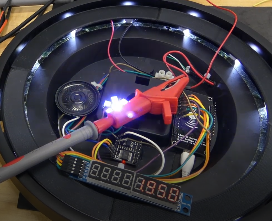
8Test again
Once the components are installed, test to ensure everything is working again.
-
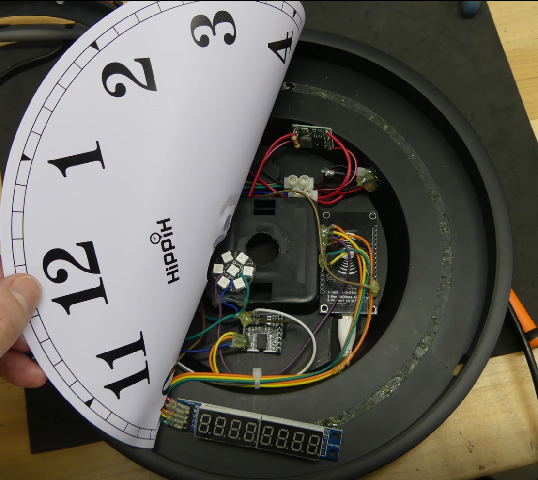
9Add back face to cover components
This back face really helps a lot to help backlight the face. It also helps reduce any components with LEDs shining through to the front.
-
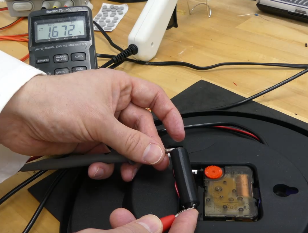
10Add fake battery, if needed
This clock motor used a AA battery to power it. You can keep the AA battery for simplicity but I figured if we were already feeding it constant power why not use that instead of using another battery. So, add in a fake AA battery wired up to a voltage regulator set as close to 1.5V as possible.
Personalized Theme Clock
Theme clock with the YouTube subscriber counter, welding flash, and sound effects.

Discussions
Become a Hackaday.io Member
Create an account to leave a comment. Already have an account? Log In.