 midierror
-
1Preparation
Don't rush this, take your time and collect the following items to help you:
- Screwdrivers
- Hex keys
- Soldering iron + solder
- Wire cutters
- Needlenose pliers
- Multimeter
- Sharp knife
I would highly recommend looking over the service manual for the ESX/EMX before starting.
Let's go!
-
2Opening the machine
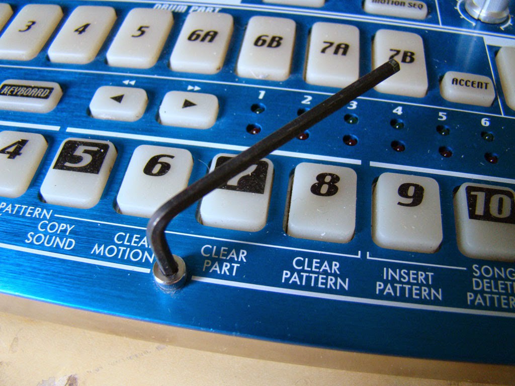
First, use your hex key to take off all of the front panel screws.
![]()
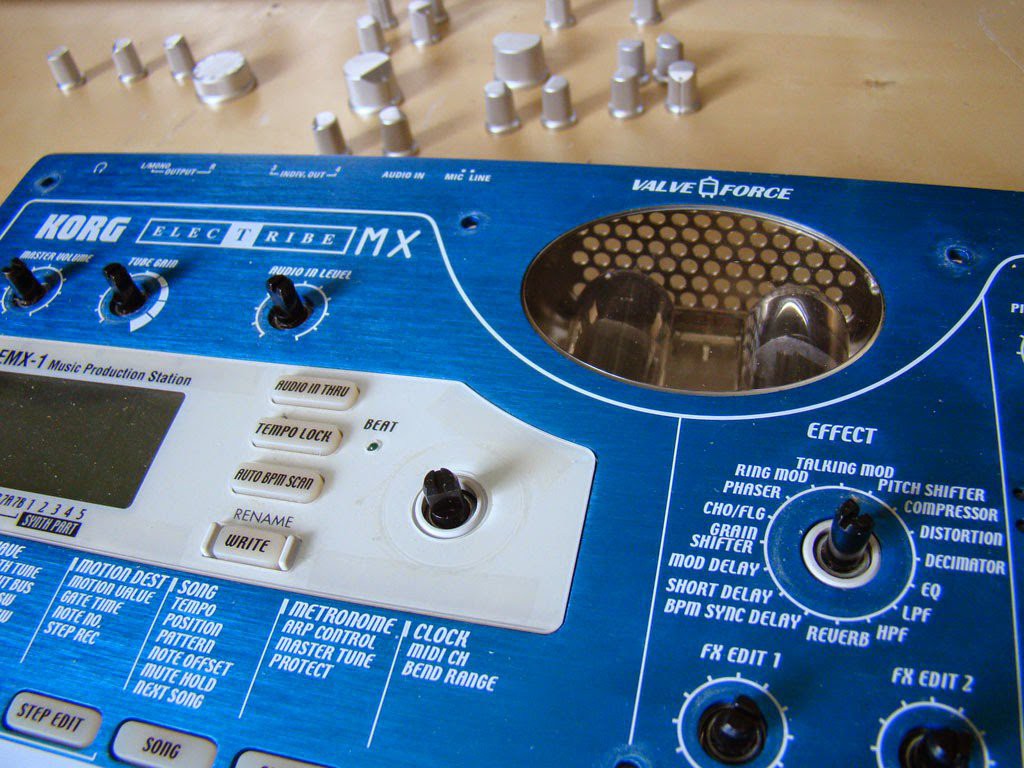
Now take off all the caps for the potentiometers (keep them in the same formation so you know where to put them back).![]()
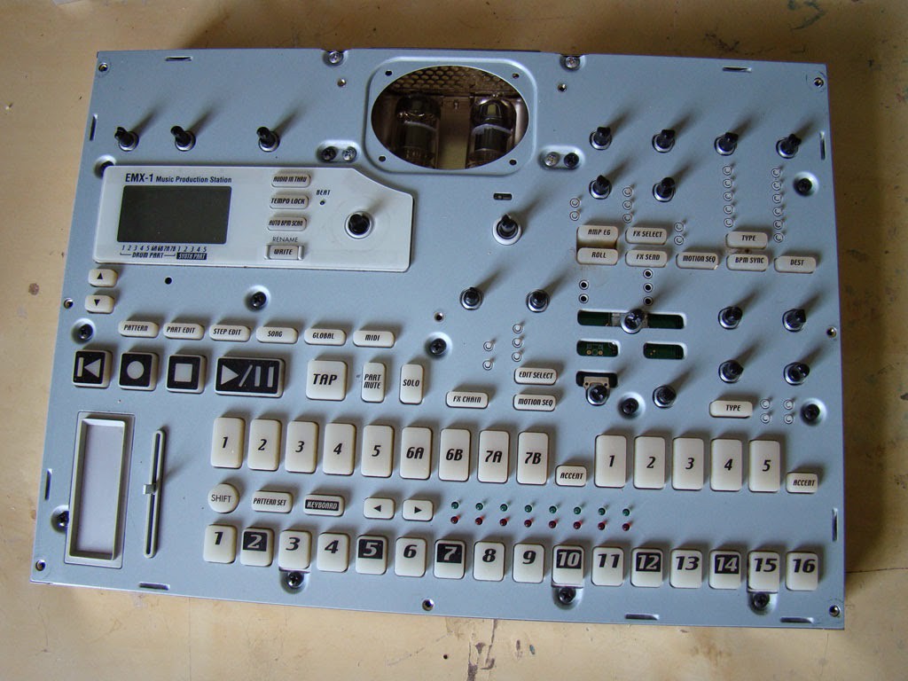
Take off the faceplate, this is what it will look like.
![]()
-
3Getting inside
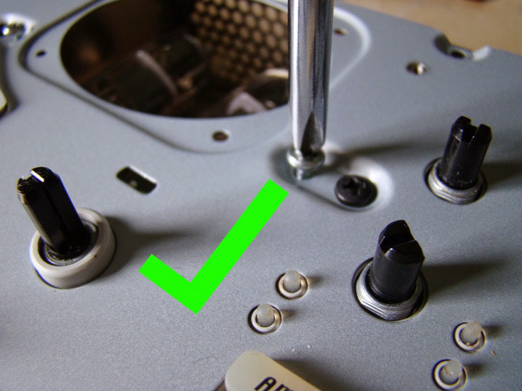
Now unscrew the silver screws near the valves. There is no need to unscrew the black ones!
![]()
![]()
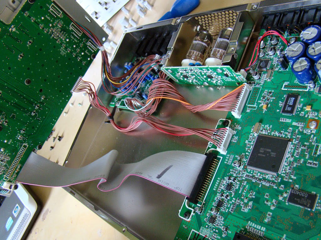
Open up the secondary panel and you should see something like the image pictured.![]()
-
4Unplug the PCBs
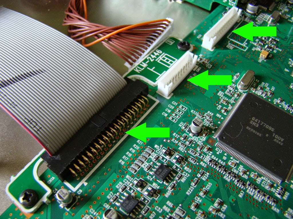
Now you need to start removing the connections between the various PCBs. Most of them have a small section to push in to enable you to remove it easily. Don`t use brute strength!
![]()
![]()
![]()
-
5Identifying components
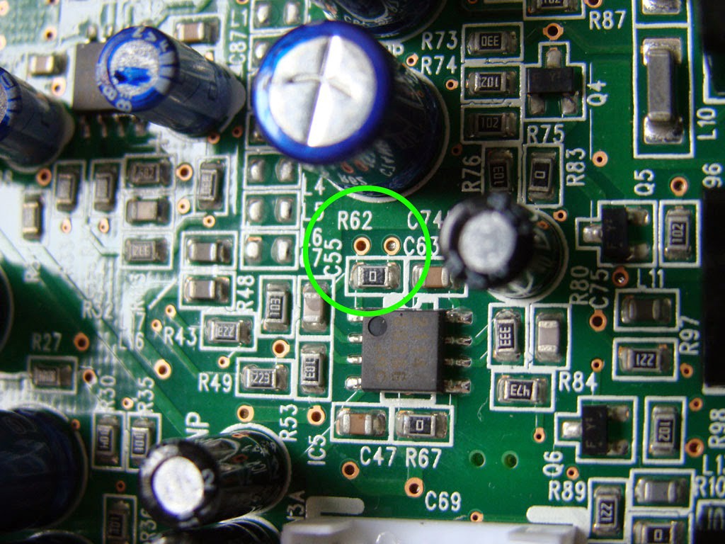
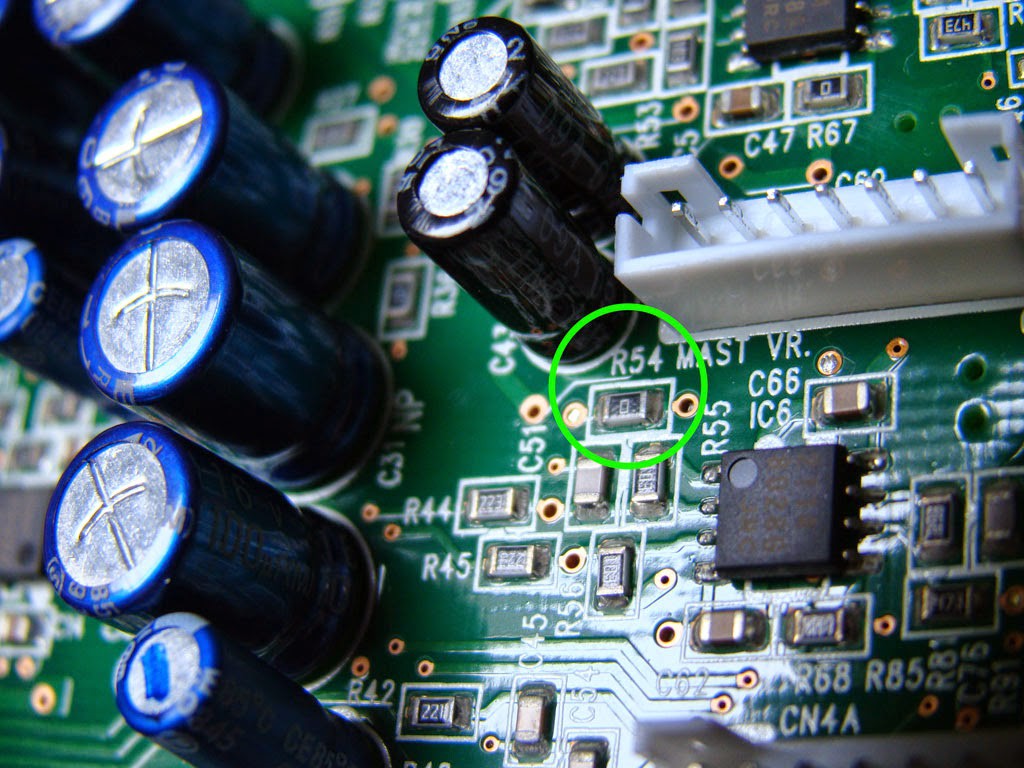
With the PCBs seperated. You need to unscrew the main PCB and identify two resistors: R54 and R62.
![]()
![]()
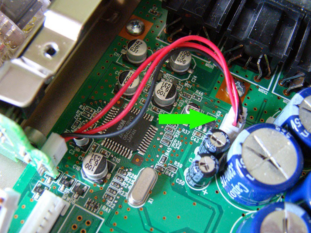
Similarly, identify two capacitors: C43 and C50 - they are next to each other. See the pictures for details.
![]()
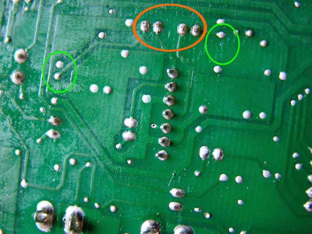
Now, it is essential to identify these exact components on the REVERSE of the board. The capacitors have been circled in orange and the resistors in green.![]()
-
6Severing the connections
Now for the 'balls out of the bath` moment. We are going to cut the connection between these components using a sharp knife. Make sure you cut where they are joined... after this there is no going back!
![]()
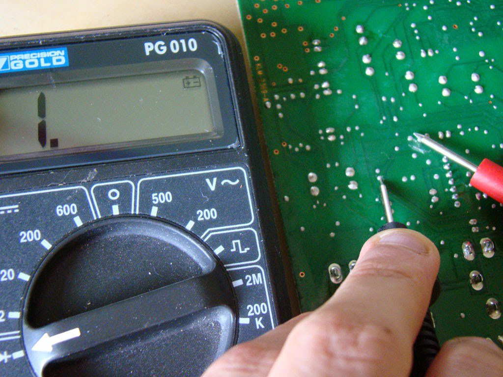
Use a multimeter to test that you have properly cut the connections.![]()
-
7Rerouting the signal
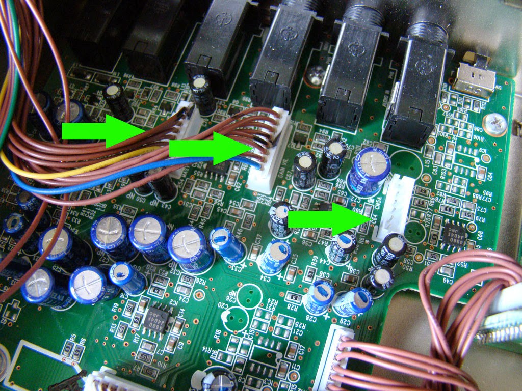
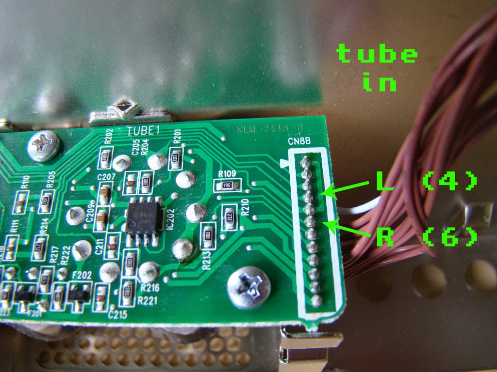
So now with the lines cut, the Korg will output nothing! We don`t want that so the signal that originally went to the valves will come back in here where we made the cuts. Below are the stereo inputs the tubes receive:
![]()
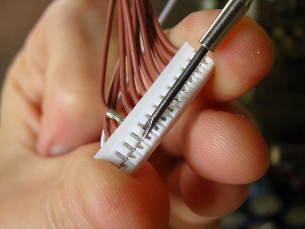
On the other end of this cable remove the pins by wedging them with a small flat edge screwdriver.
![]()
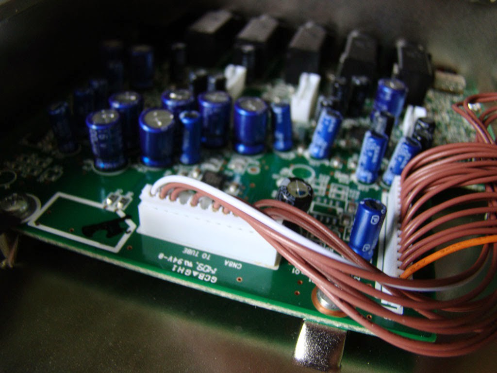
The main connection will now look like this.
![]()
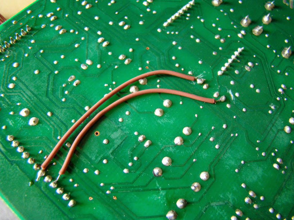
Now the signal is not physically going anywhere. We need to make these two points connect to the capacitors we disconnected earlier. This is best done on the reverse of the PCB, remember you are soldering points 4 and 6 from the valve ouput board to the outer capacitor points:
![]()
If you like, you can completely remove the valve PCB with the valves - or you can leave it in place if you like the look. I decided to take mine out. -
8Final steps!
That is it! Now make sure the connections, screws, hex keys and caps are put back in the same way as they were removed. Take a deep breath and fire up the beast!
![]()
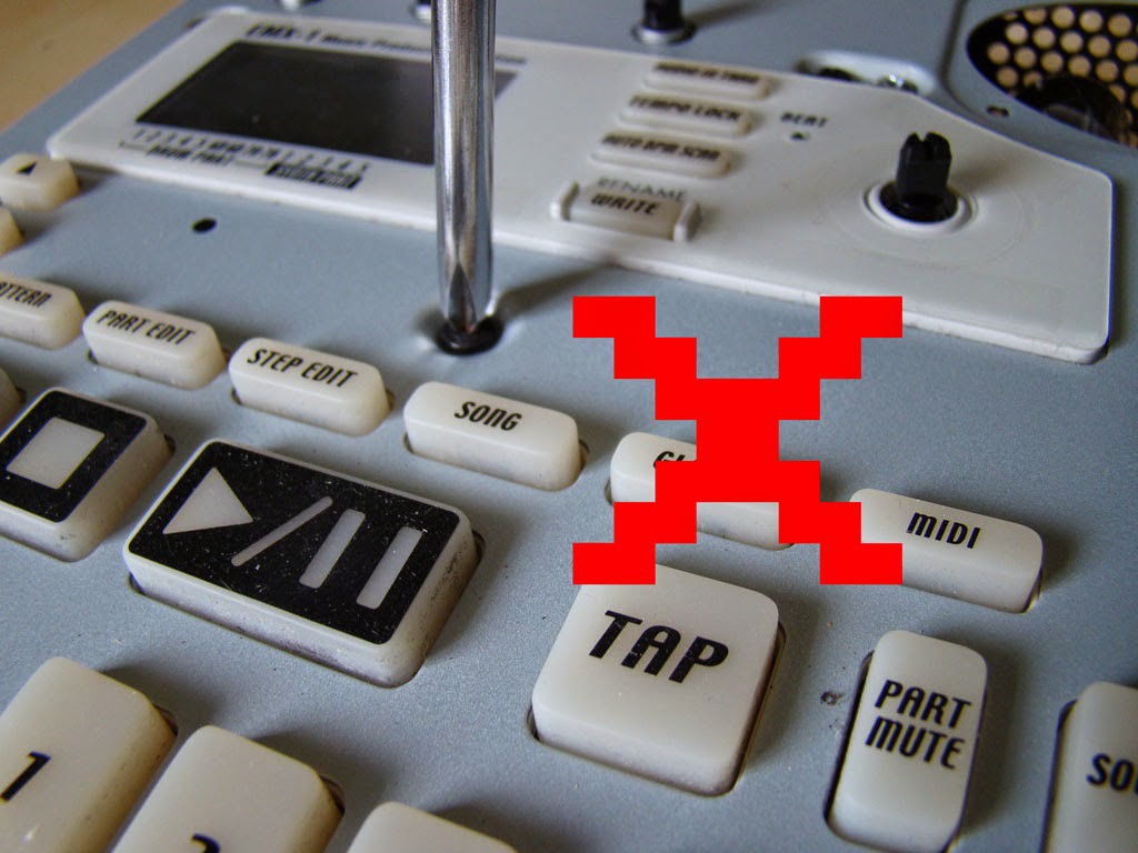
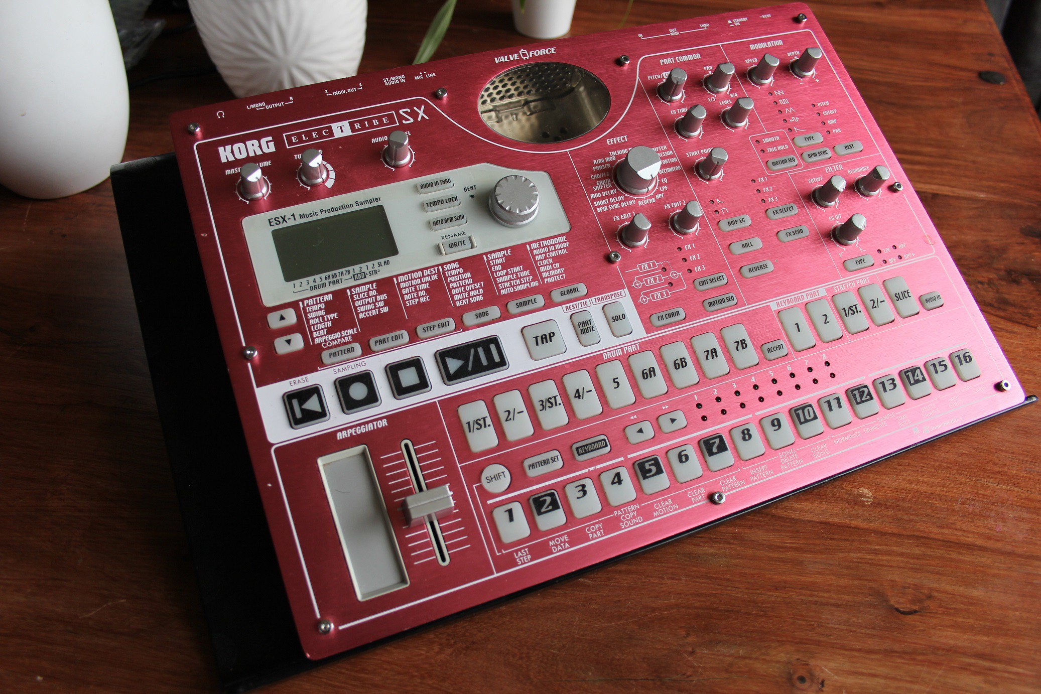
Bypassing the valves on a Korg EMX-1 / ESX-1
Some call them a gimmick. They are known to stop working. This mod gives you a cleaner sound from either machine.


Discussions
Become a Hackaday.io Member
Create an account to leave a comment. Already have an account? Log In.