 Steven Stallion
-
1Prepare the PiDP-11
If you have already built your PiDP-11 kit, you will need to remove the PCB from the case such that you have access to both sides for soldering. The Raspberry Pi should be removed from the GPIO connector.
If you are building your PiDP-11 kit, follow the Official Instructions to the point you would solder the GPIO connector to the PCB. This is not mandatory, but it does make the following steps a little easier.
-
2Solder PiDP-11 Headers
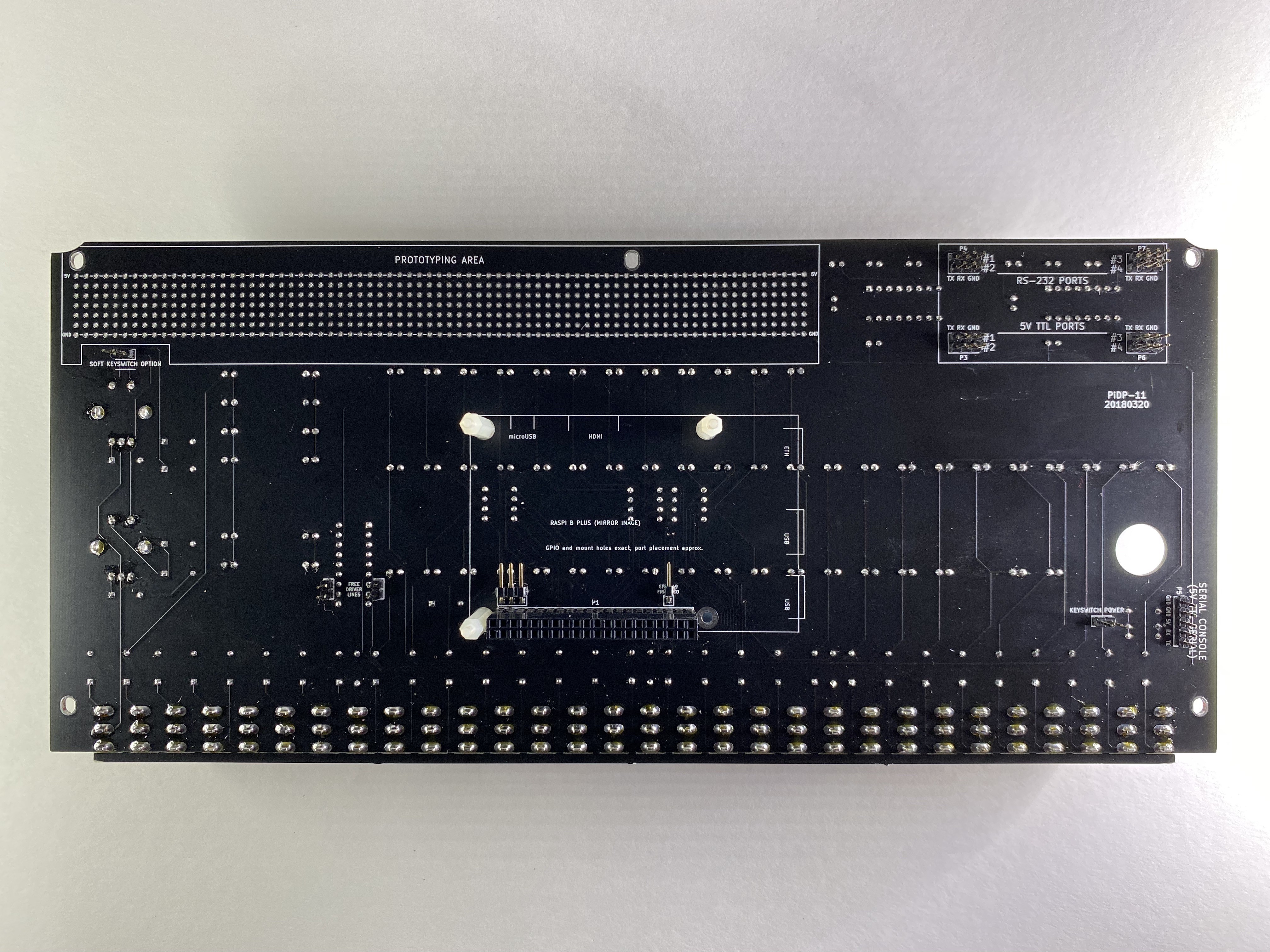
Carefully separate a single pin from the 4 position right-angle pin header using a sharp pair of cross cutters. The 3 position header should be soldered to the I2C pads, and the single position header should be soldered to the GPIO 19 FREE I/O pad above the GPIO connector on the back of the PiDP-11 PCB as shown below:
![]()
-
3Solder I/O Expander Headers
Solder the 2, 4, and 16 position vertical pin headers to the 5V/GND, I2C (J1), and I/O pads, respectively. A sacrificial breadboard can be used to align pins and ease soldering.
-
4Mount the I/O Expander
If you are building your PiDP-11 kit, continue with the Official Instructions to the point you would mount the PCB to the case.
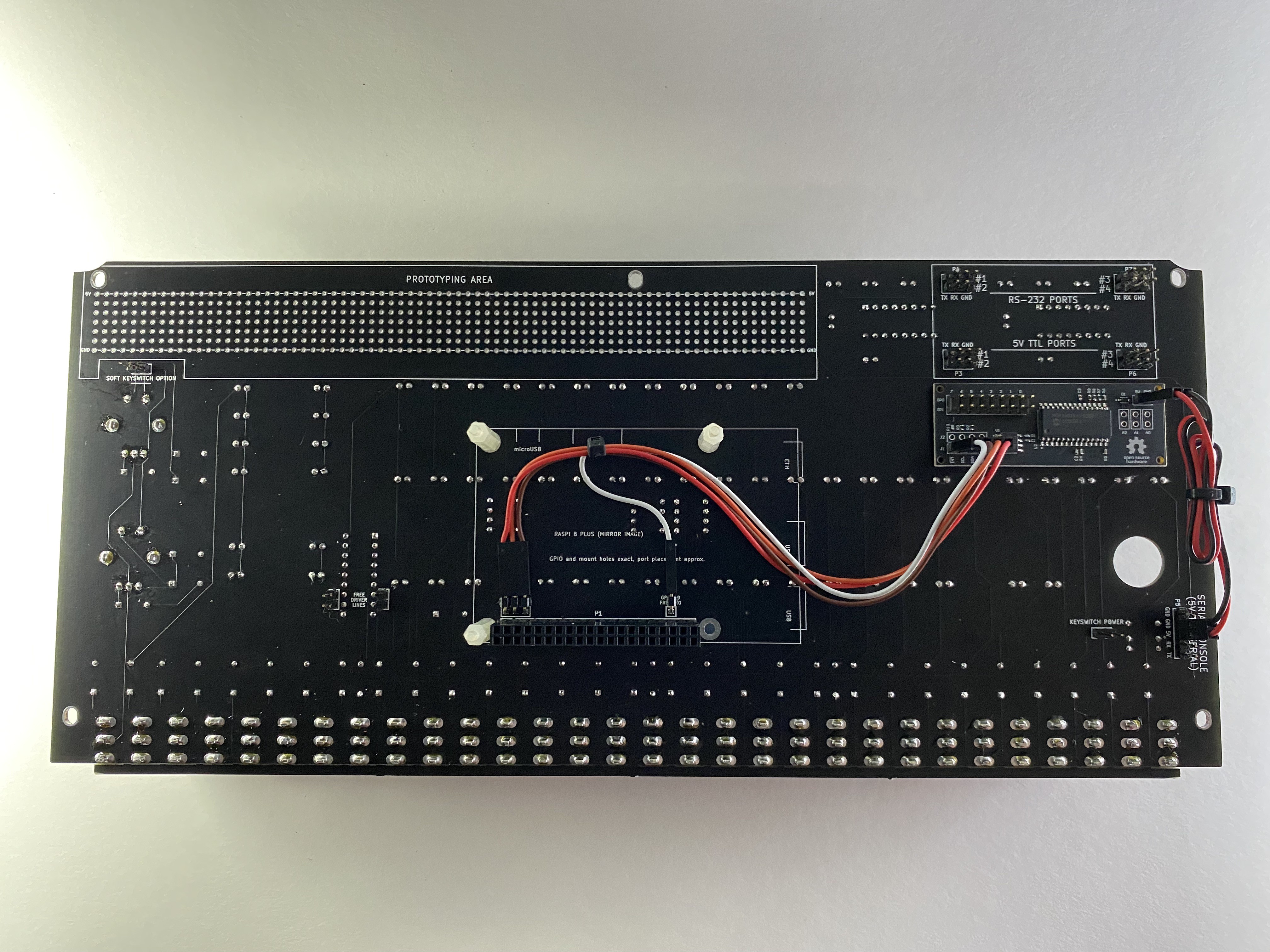
Adhere a small piece of double-sided tape (eg. VHB 4910) on the back of the I/O Expander. Remove the film from the second side and place the I/O Expander beneath the MAX232 area on the back of the PiDP-11 PCB. Press down on the I/O Expander with medium-light pressure for 30 seconds to set the adhesive.
-
5Connect Jumper Wires
Connect jumper wires from the right-angle headers soldered in Step 2 on the PiDP-11 to the 5V/GND and I2C (J1) headers on the I/O Expander. The SERIAL CONSOLE (5V TTL SERIAL) header is the most convenient location to access 5V/GND, however this will require supplying power to the Raspberry Pi directly and may require an additional shunt across the KEYSWITCH POWER header.
If all else fails, the housing can be stripped from one end of the 5V/GND jumper wires and soldered directly to the PROTOTYPING AREA.
![]()
-
6Verify Installation
Finish (re)assembling the PiDP-11 and power up the system. If I2C support has not yet been enabled on your system, follow the steps documented in Adafruit's GPIO Setup Guide to enable kernel support.
Update: The MCP23016 requires reducing the I2C bit rate to 10kHz on the Raspberry Pi to function correctly. For more details, see the Project Log.
Once I2C kernel support is enabled, the i2c-tools package should be installed to detect connected devices:
$ sudo apt-get -y install i2c-tools
The I/O Expander will respond to addresses 0x20 (the default) through 0x27. Issue the following command to verify installation:
$ i2cdetect -y 1 0x20 0x27
     0  1  2  3  4  5  6  7  8  9  a  b  c  d  e  f
00:
10:
20: 20 -- -- -- -- -- -- --
30:
40:
50:
60:
70:
If the I/O Expander fails to respond on the expected address, it may be necessary to power cycle the system.
-
7Install Software
Install the PiDP-11 I/O Expander software according to the instructions on GitHub:
$ sudo mkdir /opt/pidp11
$ cd /opt/pidp11
$ sudo wget https://github.com/sstallion/pidp11/releases/latest/download/pidp11.tar.gz
$ sudo tar -xvf pidp11.tar.gz
$ sudo /opt/pidp11/install/install.sh
After rebooting be sure to verify everything is working by following the procedure in the Usage section:
- Toggle the
HALTswitch to stop execution. - Load address
17776006using theS0-21switches followed by theLOAD ADRSswitch. - Press the
EXAMswitch to display the contents of theIODIRregister in the data display; bits 0-15 should be lit indicating that all ports are configured as inputs (POR default). - Load address
17776014using theS0-21switches followed by theLOAD ADRSswitch. - Press the
EXAMswitch to display the content of theCSRregister in the data display; bits 0-15 should be unlit indicating that no error occurred and interrupts are disabled. - Toggle the
ENABLEswitch followed byCONTto resume execution.
- Toggle the
-
8Happy Hacking!
Congratulations, you've successfully installed your I/O Expander! If you'd like to learn more about programming the MCP23016, the Datasheet and libmcp23016 is a great place to start.
PiDP-11 I/O Expander
16-Bit TTL Compatible I/O Expander for the PiDP-11 and Raspberry Pi
Discussions
Become a Hackaday.io Member
Create an account to leave a comment. Already have an account? Log In.