-
1Preparation
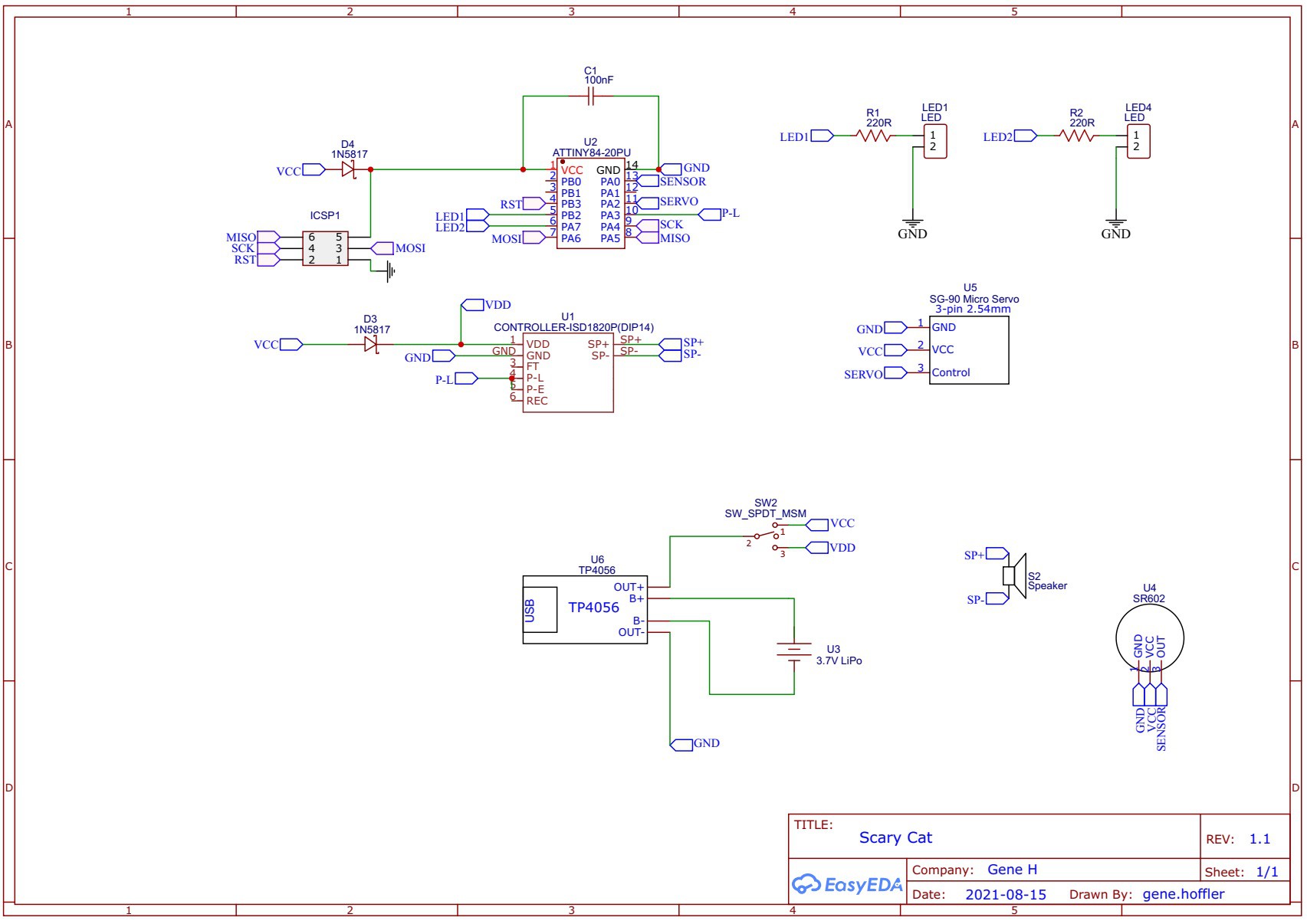
Start by reviewing the parts list and carefully selecting the necessary components. For example, there are several versions of the ISD1820 sound recording module, so be sure to purchase a kit with all of the necessary external pins needed to interface with the ATtiny84 microcontroller. I could have purchased the ISD1820 IC separately and developed a custom PCB that included all necessary functions. However, for this unique and likely onetime build, I decided to hack an ISD1820 kit and interface it directly with an ATtiny84. Since the ISD1820 kits are fairly easy to build, I recommend putting together one for testing and then another to use for the project. After obtaining all parts list, review the schematic that I created on EasyEDA to identify any potential issues.
-
2Construct an ISD1820 Kit with a Few Modifications
Put together an ISD1820 like the one in the components list. Other kit variations will likely work just as well, but the PCB size may not match the mounting holes in the base unit of the cat. DO NOT populate the three momentary switches used for "E" and "L" playback and the one used for recording. Those connections will be wired externally to the scary cat. Also, I recommend using female JST connectors on the PCB to simplify connecting the sound indicator LED, speaker, and the microphone. Please review the photo below.
![]()
-
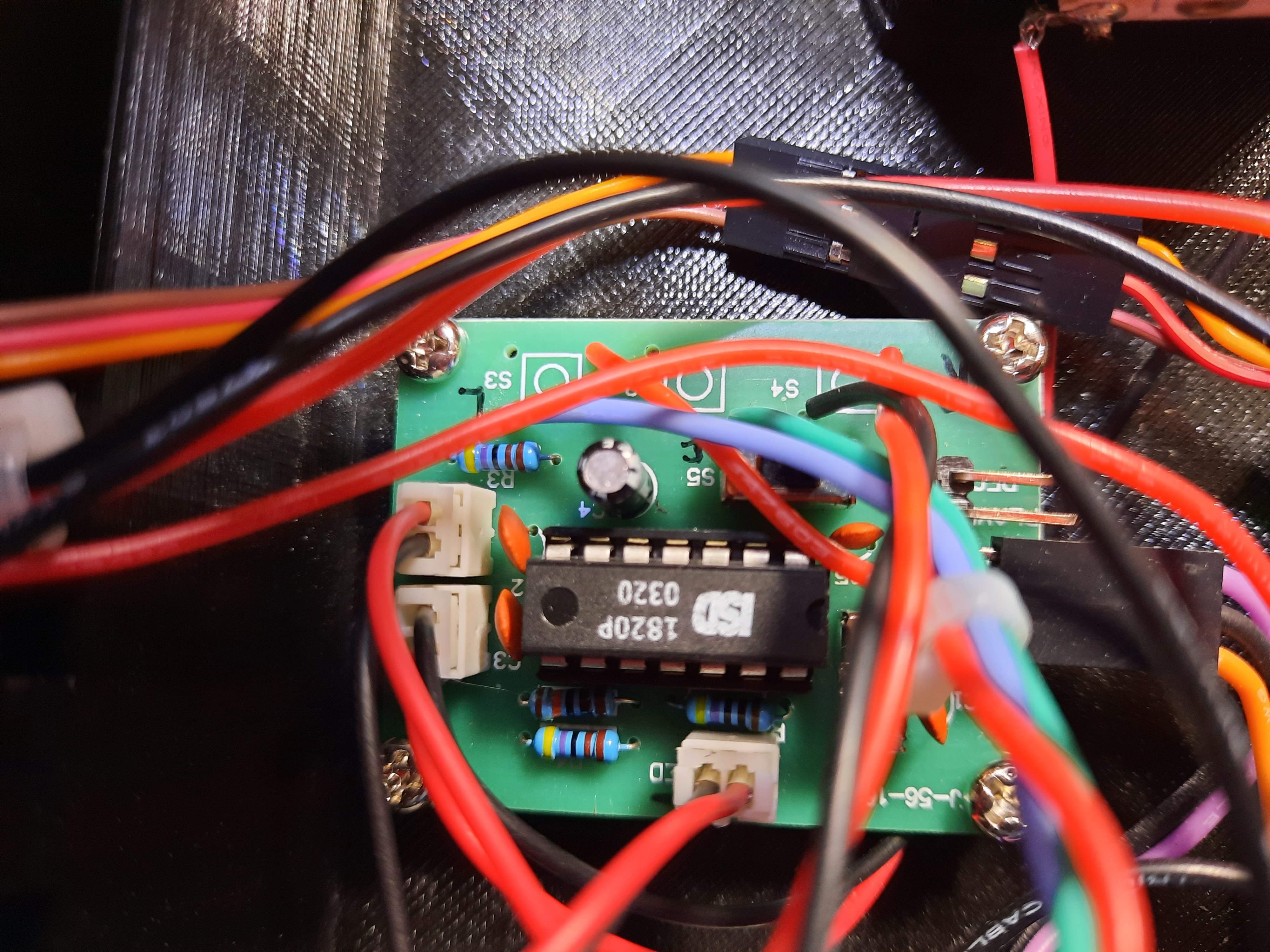
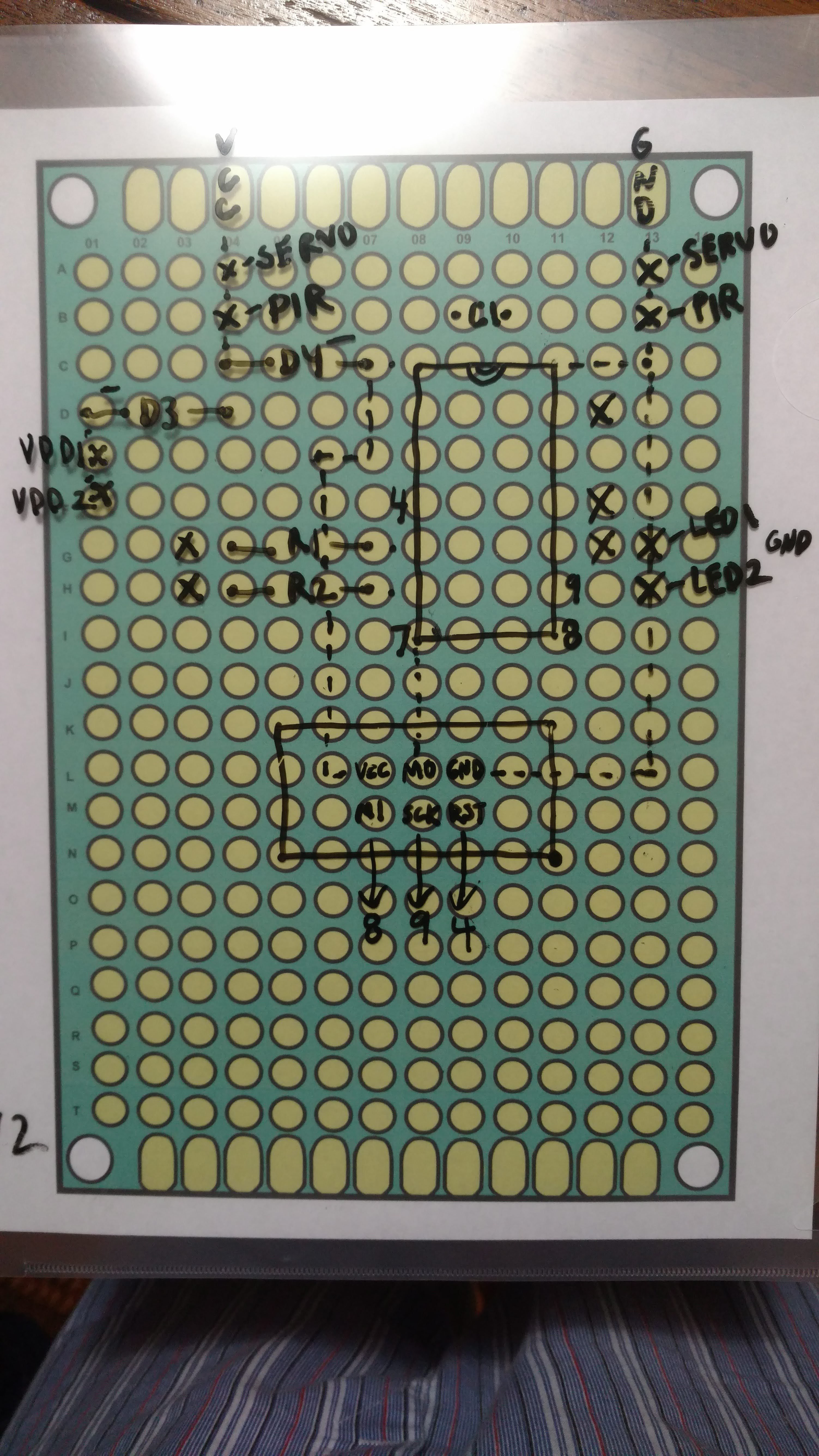
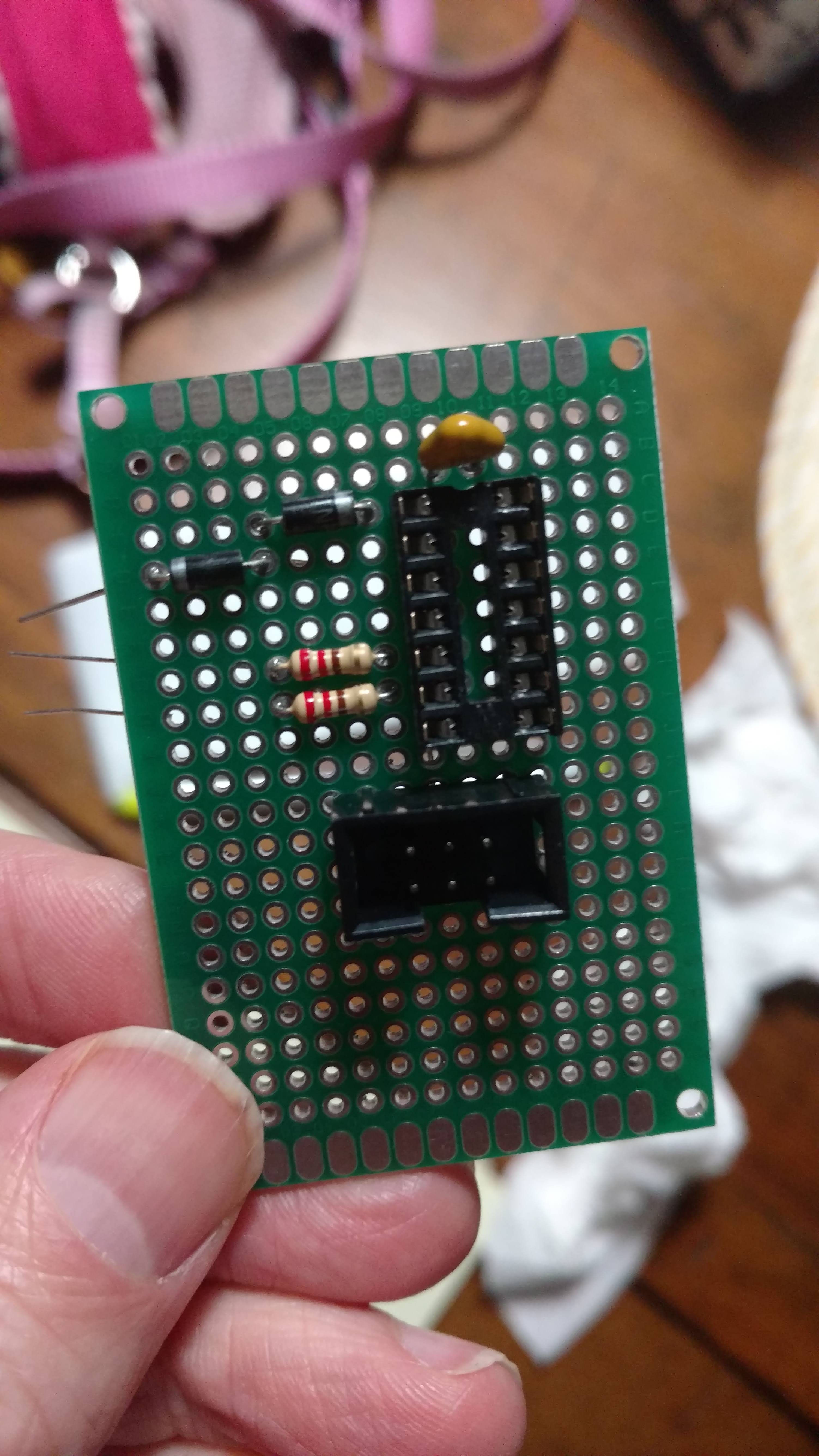
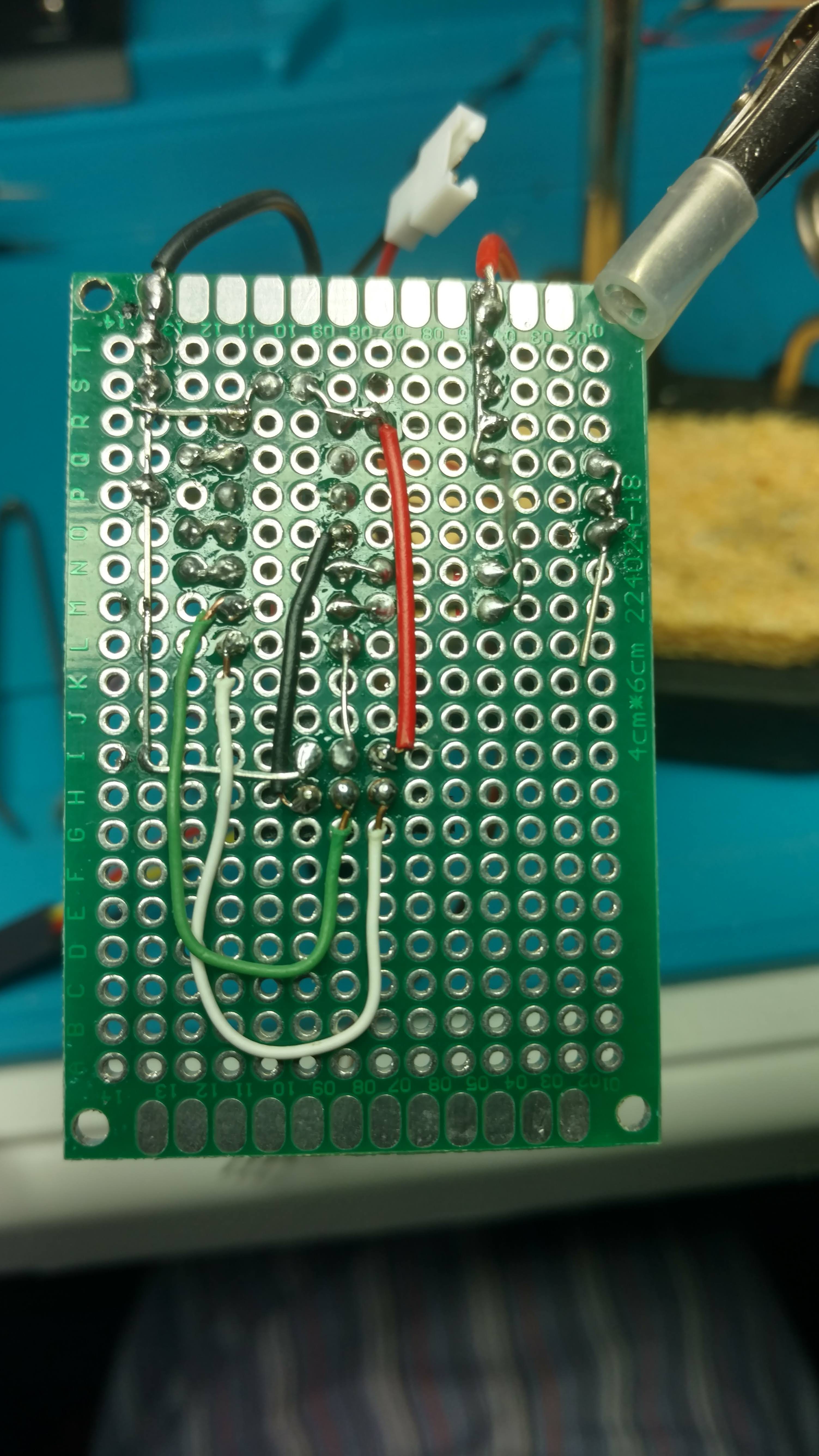
3Assemble the Prototype PCB
Using the schematic from EasyEDA, the hand-drawn board layout, and the photos below, populate the prototype PCB. You will have quite a few wires soldered and extending from the PCB to connect the main power switch, PIR sensor, servo motor, eye LEDs, and the interface connector to use with the ISD1820.
![]()
![]()
![]()
![]()
-
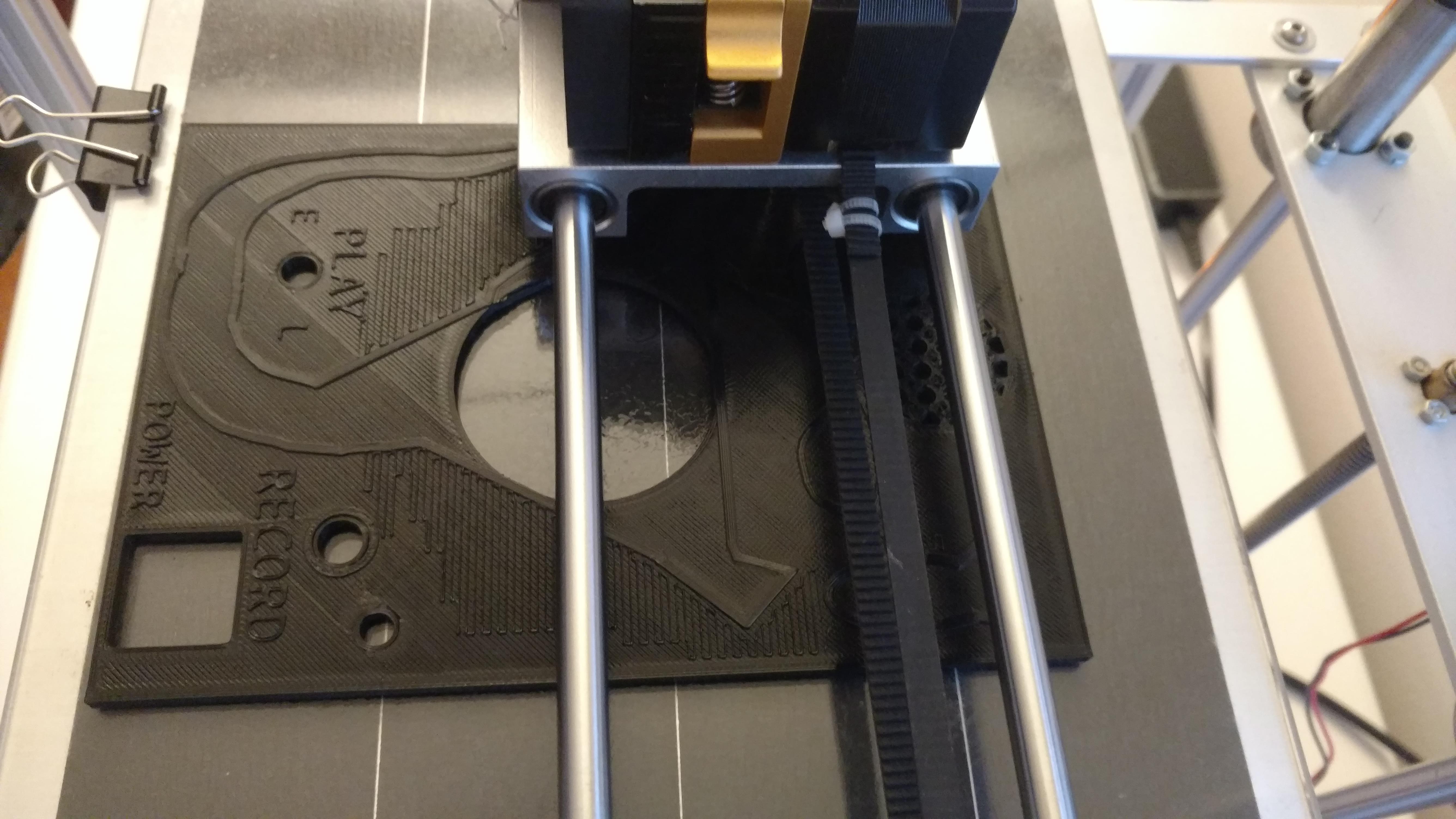
43D Printing
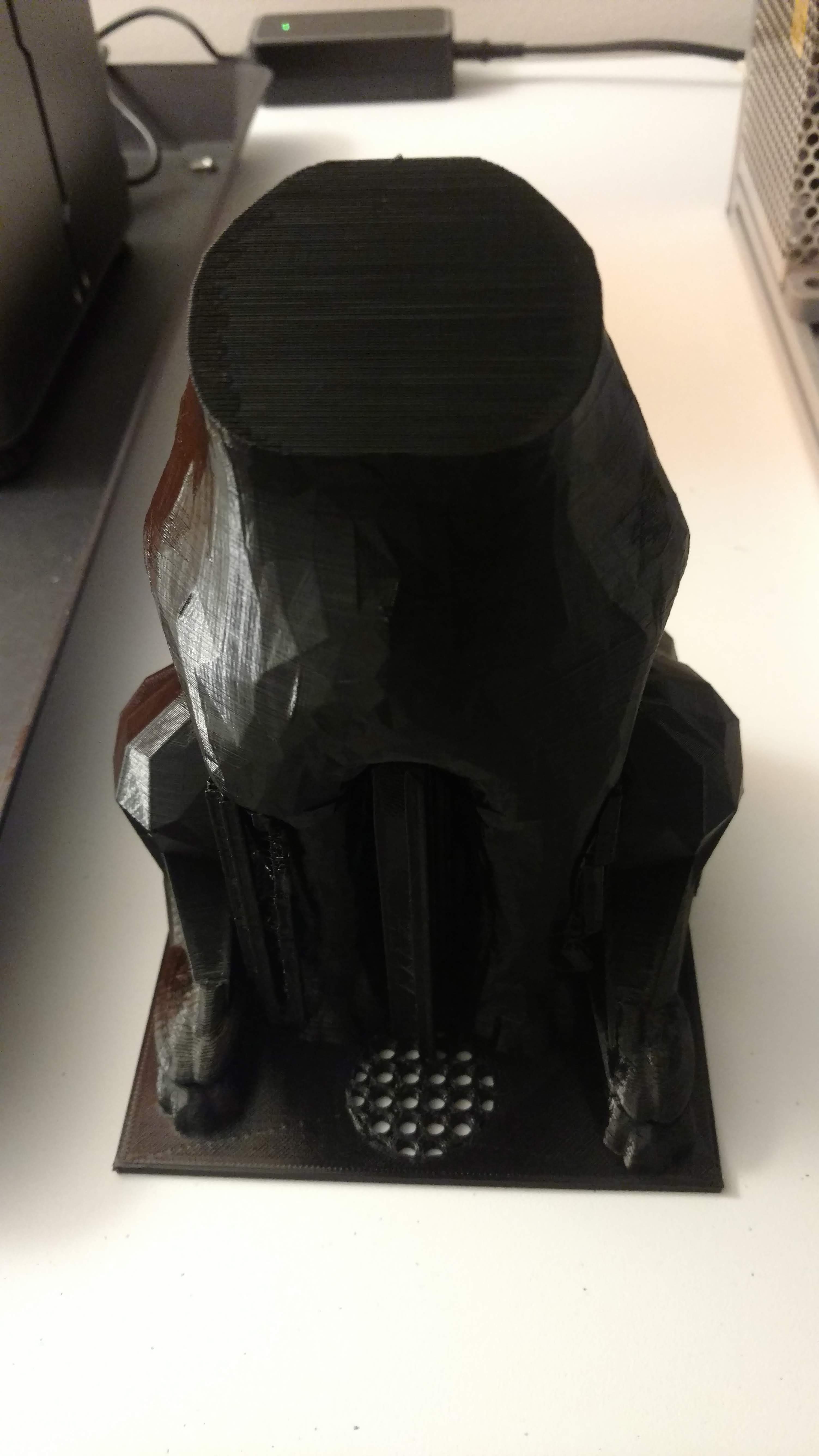
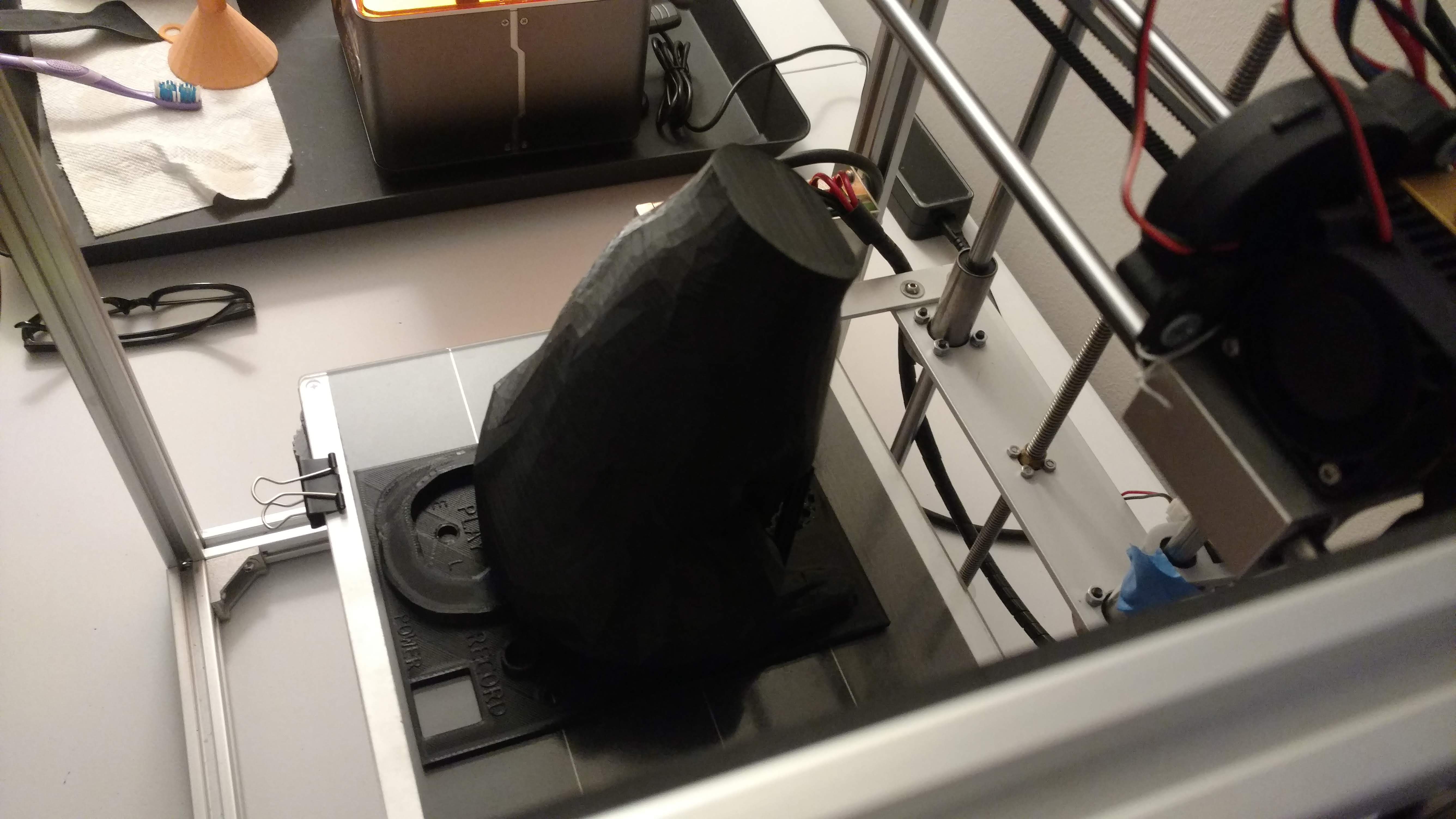
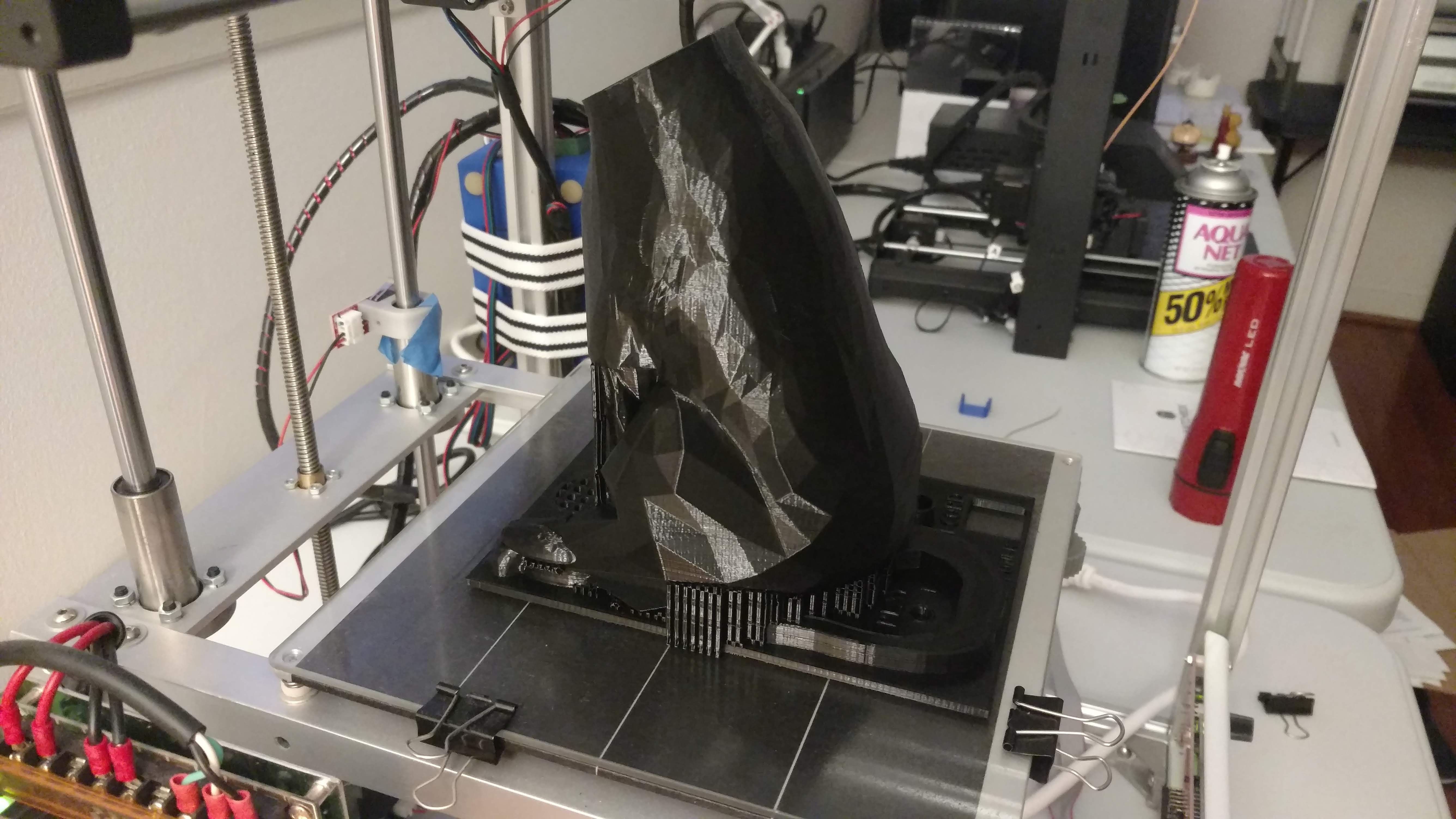
I have included the STL files that I used to 3D print the cat's head, body (with labeled base plate), and the base housing for the electronics. The cat's body took a long time to print...around 18-24 hours at the layer height and speed that I selected. That speed could certainly be increased. I also uploaded some supplementary STL files, which include a bracket to mount the cat's head to servo motor. Please be advised that I could not figure out how to print a hollow cat that included a cutout for the servo motor...my apologies. I ended up carefully marking the cutout area on the cat's neck and using a cutting tool to make a rectangular opening for the servo motor. That took some time to ensure the servo motor was centered, since the motor shift is not actually centered. I regret not taking a picture of that effort. In hindsight, I also would have accounted for the servo motor space between the cat's head and body to avoid having such a large gap. I covered it with black felt! :)
![]()
![]()
![]()
![]()
![]()
-
5Install the LED Eyes and Servo Motor for the Head
Insert the two 5mm yellow (or a color of your choice...red would be cool) into the eye holes from inside the cat's head. You may need to clean out the mount holes with a small tool. You'll need to solder on long wires beforehand to reach the base. Secure them with a proper glue. I use E6000 since it usually adheres well but can be pulled off with some effort if things go wrong. Run the long LED wires through the neck (you may need to drill a small hole), down through the cat's body, and out of its..."bottom". Fit the head mounting bracket inside the cat's head with glue and secure it to the servo motor that you installed in the beheaded cat's neck. I secured the servo motor with two screws. Run the servo motor wires (3 of them) down through the cat's body and out of the bottom hole. I used a pair of three pin connectors to make soldering the servo wires to the PCB a little easier.
-
6Program the Microcontroller
Before mounting the prototype PCB to the housing, I recommend uploading the required sketch to the ATtiny84 microcontroller with a programmer of your choice. I used a USBtinyISP type shown in the picture.
![]()
/*Sketch for the Scary Cat Project by Gene H*/ #include <SoftwareServo1.h> SoftwareServo1 Headservo; #define sensorPin A0 // Signal pin for SR602 mini PIR sensor (actual pin 13 on the ATtiny84) #define startupPeriod 8000 // Wake up time for cat in milliseconds #define maxScarePeriod 30000 // Maximum amount of time in milliseconds for cat to scare people #define minScarePeriod 10000 // Minimum amount of time in milliseconds for cat to scare people #define pwmLED1 8 // The positive side of the the LED for the left eye is attached to this pin (actual pin 5 on the ATtiny84) #define pwmLED2 A7 // The positive side of the the LED for the right eye is attached to this pin (actual pin 6 on the ATtiny84) #define servoPin 2 // Controls motion of the servo motor (actual pin 11 on the ATtiny84) #define soundPin A3 // Controls sound playback (P-L mode) from the ISD1820 Voice Recorder/Player (actual pin 10 on the ATtiny84) /* Play modes: PLAYL (P-L) - When the button is pressed (pin HIGH), the message plays until the button is released (pin LOW) * or until reaching the end of the message. PLAYE (P-E) - When the button is pressed (pin HIGH), the message plays through the * end of the message regardless if button is released (pin LOW). */ unsigned long scareTime = millis(); unsigned long startupTime = millis(); unsigned long randomTime = 0; #define UP 4 // Directions for LED fade #define DOWN -4 #define RIGHT 0 // Directions for servo movement #define LEFT 1 #define minPWM 0 // Constants for min and max PWM #define maxPWM 252 const int minAngle = 0; const int maxAngle = 180; const int midPoint = 80; // Midpoint for the head should be 90 degrees (facing forward). However, changing the servo motor to a metal version requires an 85 degree setting as a hardware correction. byte fadeIncrement = 4; //Interval in which to fade the LED byte moveDirection = LEFT; byte moveIncrement = 1; unsigned long previousFadeMillis; // millis() timing variable for fading unsigned long previousStartupMillis; unsigned long previousScareMillis; unsigned long previousHeadMillis; // millis() timing variable for controlling the servo #define fadeInterval 30 // Speed for increment #define headInterval 25 // Maximum time interval that the servo can wait before refreshing. Interval must be at most 50ms milliseconds which coincides with the SoftwareServo refresh requirement. byte fadeValue = 0; // Global Fade Value - bigger than byte and signed for rollover int moveValue = 0; void turning_head() { SoftwareServo1::refresh(); if (moveDirection == LEFT) { moveValue = moveValue + moveIncrement; if (moveValue >= maxAngle) { moveValue = maxAngle; moveDirection = RIGHT; } } else { moveValue = moveValue - moveIncrement; if (moveValue <= minAngle) { moveValue = minAngle; moveDirection = LEFT; } } Headservo.write(moveValue); // Move the servo by designated value. } void fading_eyes() { fadeValue = fadeValue + fadeIncrement; if (fadeValue == maxPWM) fadeIncrement = DOWN; // Determine if it's time to reverse fade direction. if (fadeValue == minPWM) fadeIncrement = UP; analogWrite(pwmLED1, fadeValue); // Set the brightness level of the LED attached to pin 9. analogWrite(pwmLED2, fadeValue); // Set the brightness level of the LED attached to pin 10. } void reset_head() { SoftwareServo1::refresh(); if (moveValue < midPoint) { moveValue = moveValue + moveIncrement; } if (moveValue > midPoint) { moveValue = moveValue - moveIncrement; } Headservo.write(moveValue); } void setup() { pinMode(sensorPin, INPUT); pinMode(soundPin, OUTPUT); analogWrite(pwmLED1, fadeValue); analogWrite(pwmLED2, fadeValue); previousStartupMillis = millis(); previousFadeMillis = millis(); while (millis() - previousStartupMillis < startupPeriod) { if (millis() - previousFadeMillis > fadeInterval) { fading_eyes(); previousFadeMillis = millis(); // Time stamp of previous action. } } Headservo.attach(servoPin); // Headservo is controlled by the servoPin Headservo.setMinimumPulse(496); // Set minimum pulse width based on the servo type Headservo.setMaximumPulse(2245); // Set maximum pulse width based on the servo type analogWrite(pwmLED1, 0); // Turns LEDs (eyes) off after startup period analogWrite(pwmLED2, 0); } void loop() { randomTime = random(minScarePeriod, maxScarePeriod); if (digitalRead(sensorPin) == HIGH) { previousFadeMillis = millis(); previousHeadMillis = millis(); previousScareMillis = millis(); // Use while so nothing else is allowed to occur during the scare period // Randomize the scare period between 10 and 30 seconds while ((millis() - previousScareMillis) < randomTime) { if (millis() - previousFadeMillis > fadeInterval) { fading_eyes(); previousFadeMillis = millis(); // Time stamp of previous action. } if (millis() - previousHeadMillis > headInterval) { // Determine if it's time to update. If not, nothing happens. turning_head(); previousHeadMillis = millis(); // Time stamp of previous action. } digitalWrite(soundPin, 1); // Turn on sound playback from the ISD1820 // test for and do other stuff but do not delay inside this while loop } } while (moveValue != midPoint) { // Checks servo motor (head) location and returns it to the designated midpoint (head forward) if (millis() - previousHeadMillis > headInterval) { reset_head(); previousHeadMillis = millis(); } } analogWrite(pwmLED1, 0); // Turns LEDs (eyes) off after servo motor (head) returns to midpoint analogWrite(pwmLED2, 0); digitalWrite(soundPin, 0); delay(random(2000, 8000)); // Do not let the scare period repeat immediately, wait maybe random 2 to 8 seconds // Any other external controls could go here but would not be accessible during the scare or delay periods } -
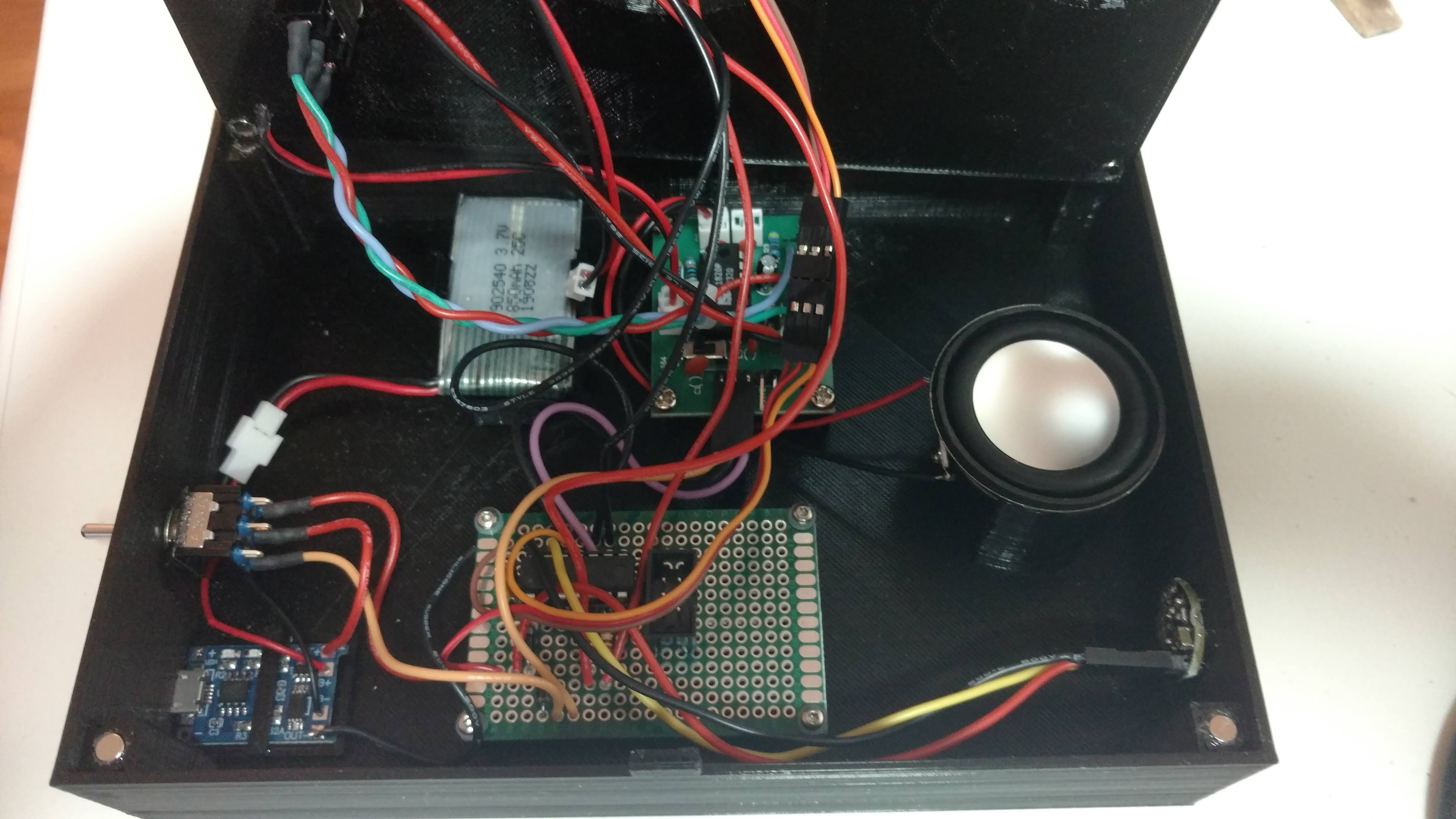
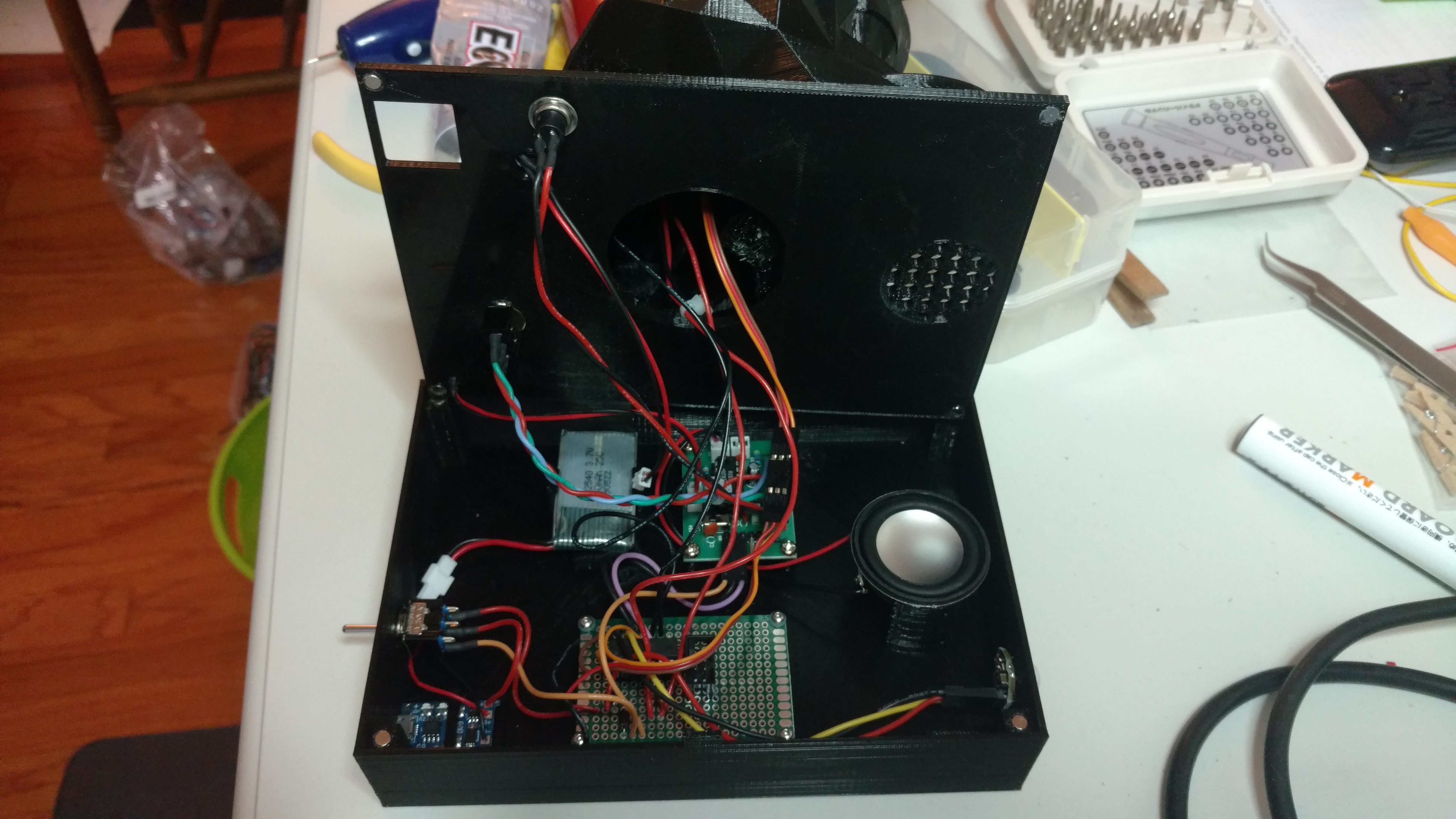
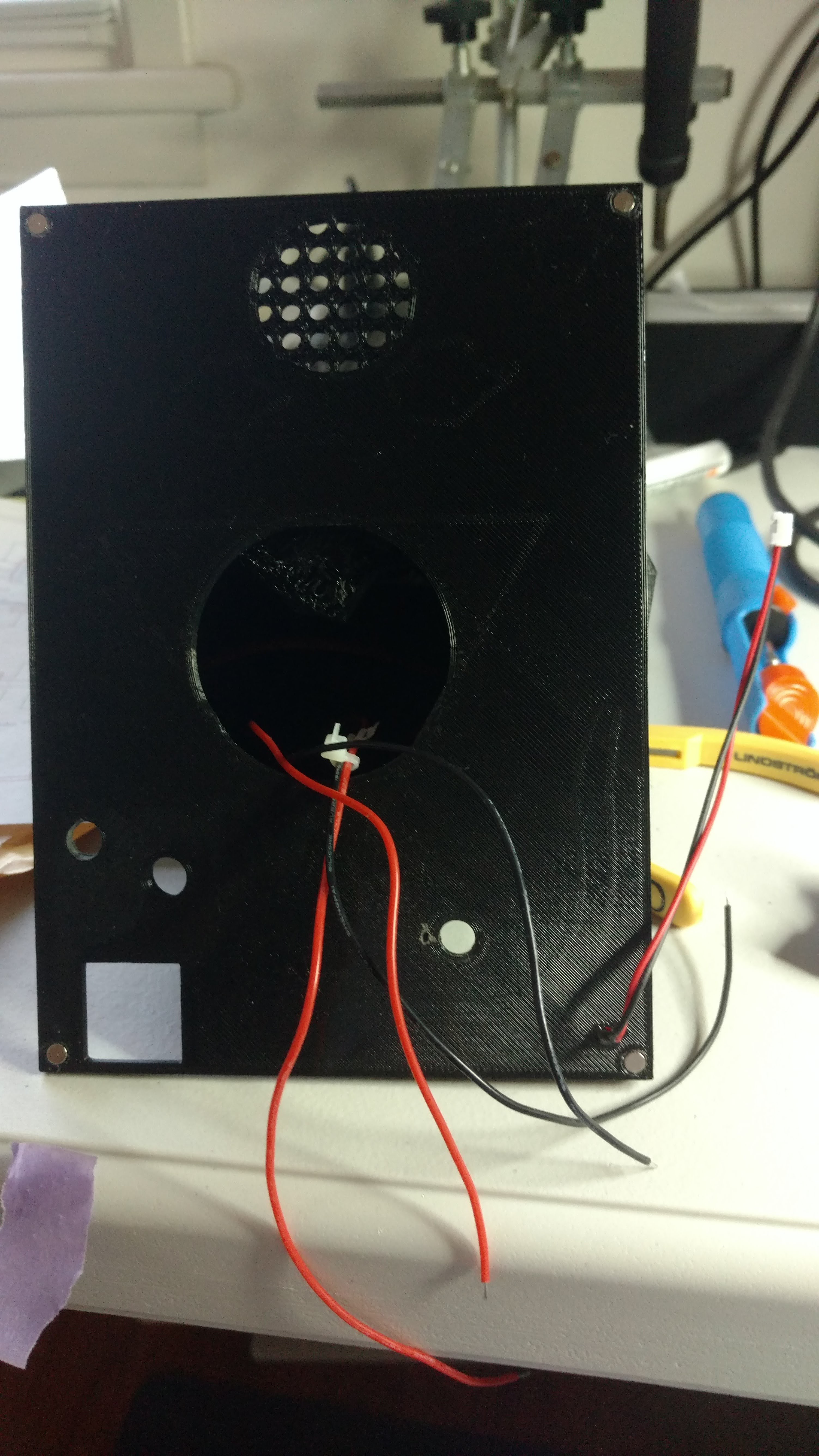
7Mount All PBCs and Components
Now that you've successfully programmed the microcontroller, you should be able to mount the ISD1820 and prototype PCB to the base housing using M2 and M3 screws. (Before proceeding, you could also perform some additional testing to confirm that everything is soldered and connected properly.) Mount the speaker, microphone, PIR sensor, switches, TP4056 module, and LiPO battery to the housing. You may need to adjust the size of the mount holes a bit depending on the dimensions of the components that you've selected, especially the switches.
![]()
![]()
![]()
![]()
![]()
![]()
-
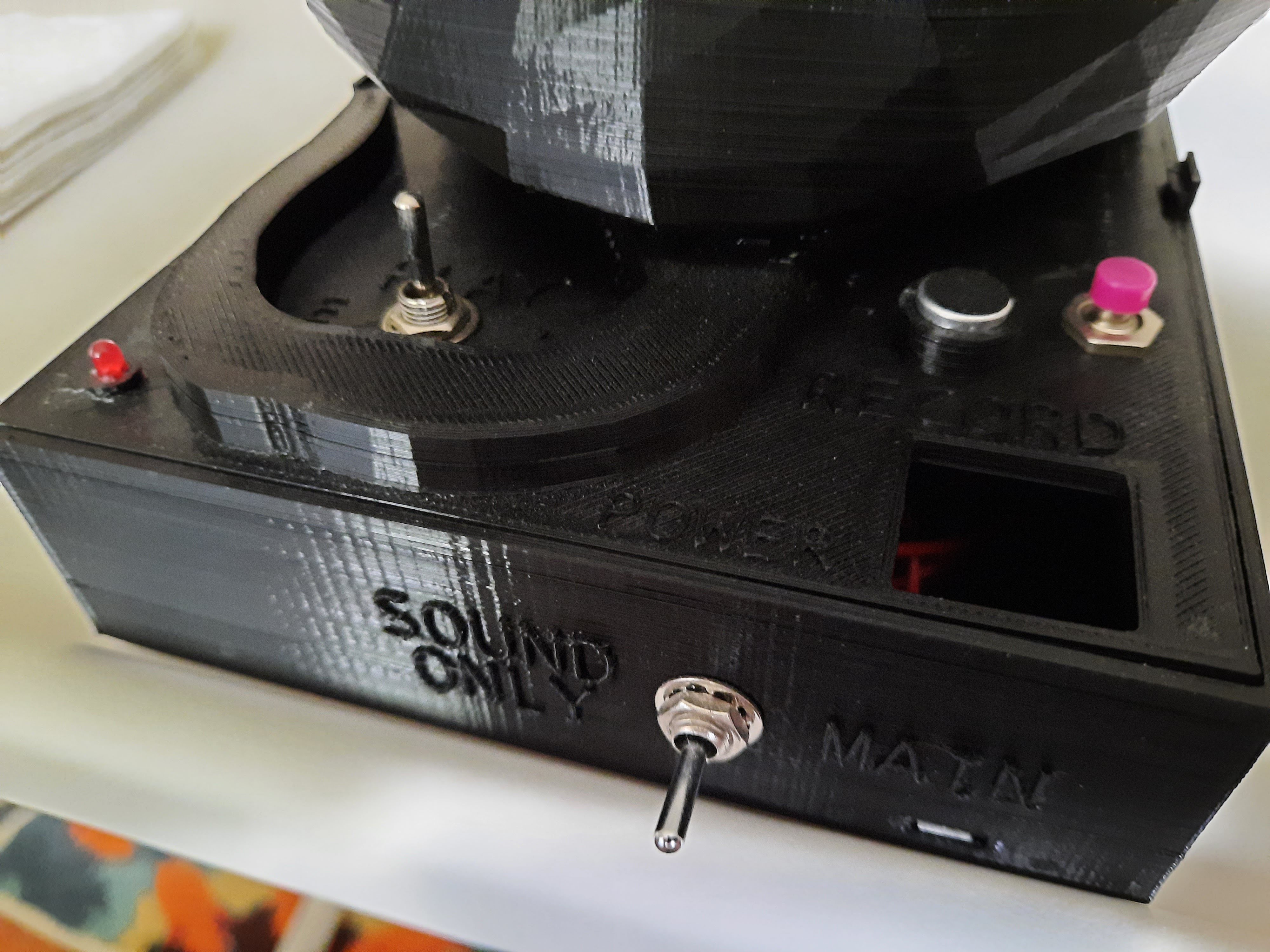
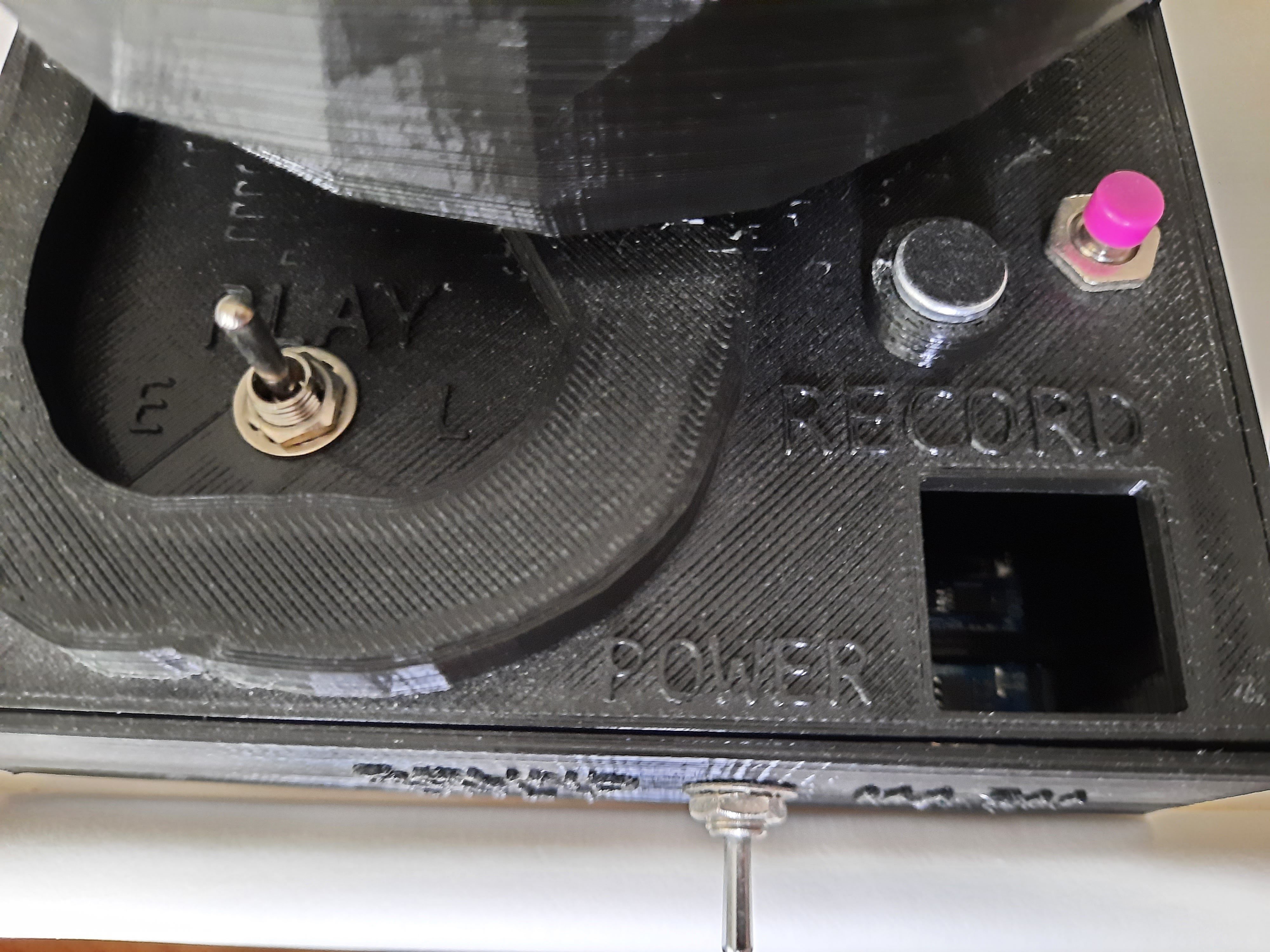
8Final Preparations
Ensure everything is connected and carefully tuck all wires into the base unit of the Scary Cat. If you haven't charged the LiPO battery yet, plug a microUSB cable into the charging port and proceed after the battery is charged. You should be able to see the indicator LED through the cutout in the housing. At this point, you'll need to record some sounds, words, etc. for your creature. Flip the main power switch to "SOUND ONLY". Move close to the microphone and then press and hold the momentary switch labeled "RECORD". Release the button when you are done recording. I think the ISD1820 only holds about 15 or 20 seconds of audio. To verify that your recording is successful, leave the main power switch set to "SOUND ONLY" and flip the momentary toggle switch labeled "PLAY" to "E" and release it. Your entire recording should play back in its entirety. If you flip the switch to "L", the recording will only play while you continue to hold the switch in the closed position. That's the difference between the "E" and "L" playback modes. I didn't design that part, so it took me a little time to figure it out!
-
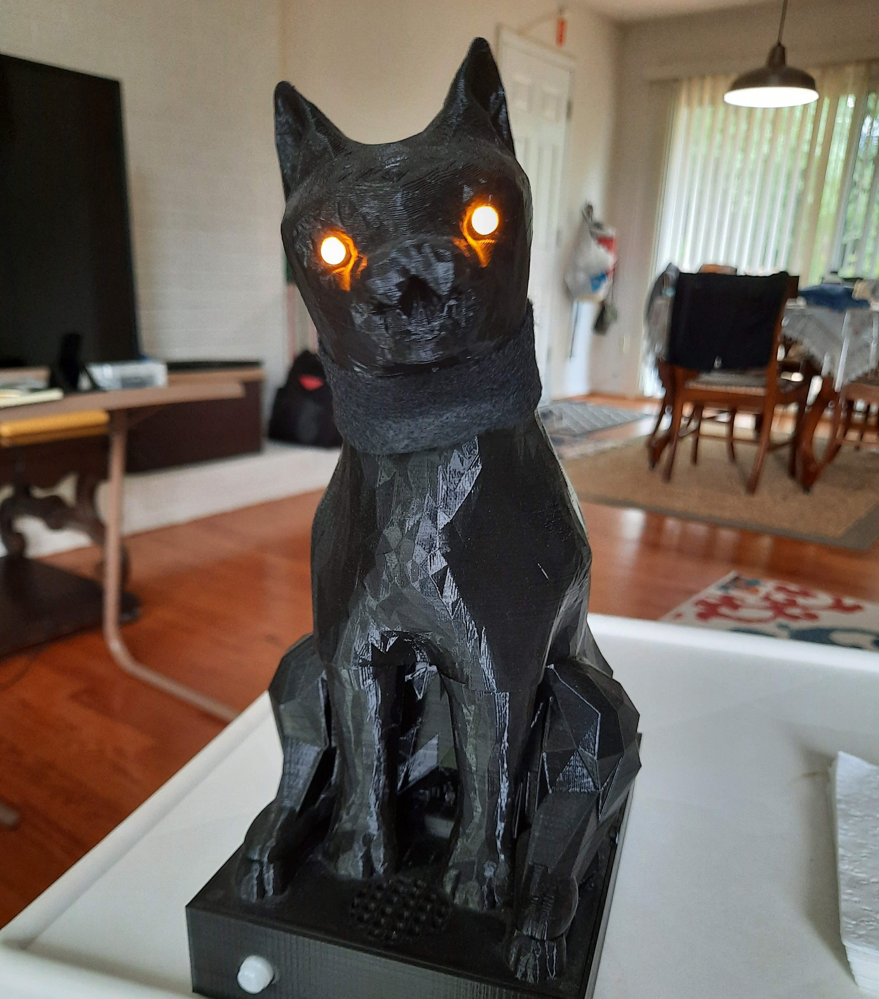
9Power Up!
It's now time to energize the scary cat and amaze all of your family and friends! Insert the cat's base plate into the main housing. You'll notice that there are retaining clips along the outside edge of the bottom housing to help keep everything together. Power up the cat by selecting "MAIN" on the primary latching switch. The cat's eyes should fade in and out for a few seconds before the cat's head is reset to the front. Make a movement in front of the PIR sensor, and the cat should come alive with a turning head, slowly fading eyes, and playback of your recording sound. For even more Halloween scares, set it on your porch to startle some unsuspecting trick or treaters. Just be sure that they don't steal it! :)
-
10Finishing Touches
To ensure that the base doesn't detach from the cat's body, I recommend inserting and gluing eight magnets (four on the base and four opposing ones on the underside of the labeled insert. You may have to clean out the recessed holes a bit if you added supports with your 3D printer. Also, I used E6000 to attach four rubber feet to the bottom of the project to keep it from sliding around. Finally, I put a piece of felt around the cat's neck to cover the gap between the head and body where the servo goes. I would certainly try to fix that if I were to do it again.
I am grateful for my family's support during this making effort. Also, I'd like to give a special thank you to my great friend Paul for his teaching and assistance.
Good luck and Happy Halloween!
![]()
https://cdn.hackaday.io/files/1813177757466528/Updated-Hackaday-Video.mp4
Fear the Scary Cat!
After visiting a local Halloween store, I thought it would be cool to create my own interactive scary cat with lights, sound, and movement.


Discussions
Become a Hackaday.io Member
Create an account to leave a comment. Already have an account? Log In.